
Samsung Galaxy S20 Plus Motherboard Replacement
Duration: 45 minutes
Steps: 42 Steps
Ready to give your Galaxy S20 Plus a fresh start? Follow these easy steps to swap out the motherboard, but don't forget to grab some replacement adhesive to seal the deal! If you hit a snag, don't stress—just schedule a repair for some expert help.
Step 1


If you poked the tool into the other hole, no worries—the microphone and its protective gasket are chilling safely out of the way.
- Grab a SIM card eject tool, a small screwdriver, or even a straightened paperclip, and gently insert it into the tiny hole on the SIM tray. You’ll find it on the top edge of your phone, right next to the plastic antenna band.
- Press in with a little force, and voilà, the tray will pop right out!
Tools Used

Step 2


The SIM card is ready to jump ship—just tilt the tray and it’ll slide right out.
- Pop out that SIM card tray like a pro! It's easier than you think.
- When you're ready to put the SIM card back in, just make sure it lines up perfectly with the tray. It’s like a puzzle piece!
- Don't forget about that thin rubber gasket around the SIM tray; it’s your phone’s little superhero against water and dust. If it’s looking worse for wear, consider swapping it out or getting a new SIM tray to keep your device safe and sound.
Step 3

Make sure to unplug and power down your phone before diving in. Safety first, right?
A hair dryer, heat gun, or hot plate can be handy tools, but keep an eye on the heat—your phone’s display and battery aren’t fans of getting too hot. Use gentle warmth and avoid overheating to keep things safe and sound. If you need help, you can always schedule a repair.
- Warm up an iOpener and gently press it onto the bottom edge of the back cover for about two minutes. This helps loosen the adhesive so you can lift the cover more easily. If you need a hand, you can always schedule a repair.
Tools Used

Step 4


Go easy with the pick—too much muscle and you might turn that back cover glass into a modern art project.
Cracked display giving you trouble? Try slapping on some clear packing tape to help the suction cup grip. Super-stubborn glass? Super-strong tape or even a little superglue on the suction cup can save the day.
Getting the screen loose can be a bit of a dance thanks to those tight tolerances. You’ll probably need to reheat the edge with your iOpener and have a few goes with the suction cup before it finally budges.
If that gap just won’t happen, hit the edge with a little more heat and give it another shot.
- Stick a suction cup onto the back of your phone, aiming for the center of the bottom edge. Think of it as giving your phone a little hat.
- Give the suction cup a firm, steady pull to start cracking open a gap between the back cover and the frame. No need to arm wrestle, just steady pressure.
- Slide the tip of an opening pick into the gap you’ve made. You’re basically a phone ninja now.
Tools Used
Step 5


Be careful near the edges of the phone where the glass curves—trying to cut the adhesive there might crack the glass. Take it slow and steady to keep everything intact.
- Gently slide the pick along the bottom edge, back and forth, to cut through the adhesive like a pro.
- Keep the opening pick in place to stop the adhesive from sealing itself back up.
Step 6

- Warm up the left edge of the back cover with a heated iOpener for about two minutes. Give it a nice spa treatment to loosen things up!
Tools Used
Step 7


- Stick a suction cup on the back of your phone, aiming for the center along the left edge.
- Give the suction cup a confident pull—steady and strong—to open up a gap between the back cover and the frame.
- Slide the pointed end of an opening pick into that gap you just made.
- If the adhesive is being stubborn, add a few drops of high-proof (over 90%) isopropyl alcohol into the seam to help loosen things up.
Handle the pick with care—too much pressure and you might just shatter that back cover glass!
Since the fit is pretty snug, don’t be discouraged if you need a few tries to get it right. The curved glass edge means you won’t get your pick in very far, but as long as the tip is tucked just underneath the glass edge, you’re good to go. If you’re struggling to create a gap, try applying a little more heat to loosen things up and give it another shot.
Step 8


- Once you've got the pick under the edge of the glass, give it a little tilt and slide it in deeper to loosen up that stubborn adhesive and free the back cover.
Step 9


Watch out around the ridge near the volume and power buttons—the glass cutout can be a bit more fragile here and might crack if you're not careful. Take it slow and steady, and if you need help, you can always schedule a repair.
- Run the pick along the left side of your phone to break up that stubborn adhesive holding the back cover.
- Leave the pick chilling under the left edge—think of it as a doorstop for glue, so it doesn't sneakily reseal itself.
Step 10

You can use a hair dryer, heat gun, or hot plate to warm things up, but don’t cook your phone—too much heat can mess up the screen or battery.
- Warm up the right edge of the back cover with a heated iOpener for a solid two minutes. Let the heat work its magic before moving on.
Tools Used
Step 11


Just like you did with the last edge, angle the opening pick downward so you can slide it all the way under the back cover.
- Stick a suction cup onto the back of your phone, aiming for the center of the right edge like a pro.
- Give that suction cup a good, firm tug to open up a little gap between the back cover and the frame—you're doing great!
- Slide the tip of an opening pick into that gap you just created. Easy peasy!
Step 12


As you're popping off the back cover, you might notice one or both of the picks making a break for it and falling out. No worries—just set them aside for now. The bottom edge won’t snap back together at this point, so you’re good to go.
- Gently glide your pick along the right edge of the phone to break the adhesive on the back cover. Keep it steady, you got this!
- Once you've slid your pick under the right edge of the glass near the top, leave it there to keep the adhesive from sticking back together. Easy, right?
Step 13

- Lay a heated iOpener across the top edge of the back cover for a couple of minutes to help loosen things up.
Tools Used
Step 14


Heads up: the glass around the back cover corners is curved and loves to crack under pressure. Go easy here to keep your back cover in one piece!
If the slicing starts to feel tough, hit pause and warm things up again before moving forward.
- Carefully slide the pick from the right edge of your device, hugging that top right corner as you go.
- Keep on slicing along the top edge and around to the left side until you've fully separated the back cover adhesive.
Step 15


- Gently lift the back cover, using opening picks to slice through any stubborn adhesive along the way. Once it's loose, remove the back cover completely. During reassembly, this is a good moment to power on your device and check all functions before sealing it back up—just remember to turn it off completely before continuing. Use tweezers or your fingers to clear away any leftover adhesive chunks; applying a bit of heat can help loosen stubborn spots. If you're using custom-cut adhesives, follow this guide. For double-sided tape, stick to this guide. If you need a hand, you can always schedule a repair.
Tools Used

Step 16

Keep an eye on where each screw goes—mixing them up is a headache you don’t need!
- Grab your trusty Phillips #00 screwdriver and get ready to tackle those six 4 mm-long screws holding the motherboard bracket in place. You've got this!
Tools Used

Step 17


Hold off on taking out the bracket completely—it's still hanging out with the wireless charging coil.
- Grab a pair of tweezers and gently lift the motherboard bracket away from the plastic midframe. Easy does it — just a gentle tug to unclip it.
Tools Used
Step 18


- Lift the motherboard bracket just enough to sneak a peek at the orange battery connector.
Step 19


When disconnecting connectors like these, keep an eye out—don't let those tiny surface-mounted components nearby sneak away or get knocked loose. Stay gentle and steady, and if you need a hand, you can always schedule a repair.
- Time to getthis repair started! Use a spudger to carefully pry up and disconnect thebattery connector.
Tools Used

Step 20


- Grab your trusty spudger and gently pop up the wireless charging coil connector—think of it as giving it a friendly nudge to disconnect.
Tools Used
Step 21


- Grab your tweezers and gently lift the wireless charging coil off—it’s like peeling a sticker, but way more high-tech.
- Take out the wireless charging coil and give yourself a mental high five.
- When putting it all back together, start by reconnecting the charging coil and battery connectors, then secure those motherboard bracket screws so everything lines up. Press the coil pad down so it sticks snugly.
Tools Used
Step 22

- Grab your Phillips #00 screwdriver and take out the five 4 mm screws holding the loudspeaker and lower midframe.
Tools Used


Step 24


- Grab your trusty spudger and gently pop up those main and auxiliary flex cables from the daughterboard hanging out near the bottom of your device.
- When you’re reconnecting these press connectors, line them up with care, press down on one side till you get that satisfying click, then do the same on the other. Steer clear of pressing in the middle—misalignments can mean bent pins and a world of trouble. Take it slow and you’ll keep everything happy and healthy.
Tools Used
Step 25


- Grab your trusty spudger and gently pop up the main and auxiliary flex cables from the motherboard. Easy does it—no need to rush!
Tools Used
Step 26


- Lift up those main and auxiliary flex cables with care and set them aside.
Step 27


- Gently lift and detach the left 5G antenna cable from the motherboard.
Step 28


- Grab your spudger and gently pry up the main display flex cable from the motherboard. Keep it careful—you're disconnecting a key component, but there's no rush. If you run into trouble, remember you can always schedule a repair for extra help.
Tools Used
Step 29


- Gently lift and bend the display and left 5G antenna flex cables away from the motherboard and battery, keeping everything safe and snug.
Step 30

- Grab your Phillips #00 screwdriver and spin out the three 4 mm screws holding down the upper midframe—easy does it!
Tools Used
Step 31


- Grab your trusty spudger and slide its tip into the notch on the right side of the upper midframe. Give it a gentle wiggle to pop those clips loose.
- Lift off the upper midframe and set it aside—like a pro!
Tools Used
Step 32


- Grab your spudger and pop up the right 5G antenna flex cable from the motherboard. It’s like giving it a gentle nudge to say, ‘Hey, time to move!’
- Take your tweezers and carefully bend that cable out of the way, making space for the next move. Think of it as rearranging furniture at a tiny tech party.
Step 33


- Gently pry up and disconnect that side button flex cable from the motherboard—think of it as peeling away a sticker. Then, carefully bend the cable out of the way of the motherboard, keeping it out of harm’s way. If you need a hand, you can always schedule a repair.
Step 34


- Gently pry up the front-facing camera flex cable and disconnect it from the motherboard. Take your time, no rush!
- Once it's free, carefully bend the cable out of the way so it doesn't get caught on anything while you continue working.
Step 35


- Gently lift and unplug the upper 5G antenna cable from the motherboard.
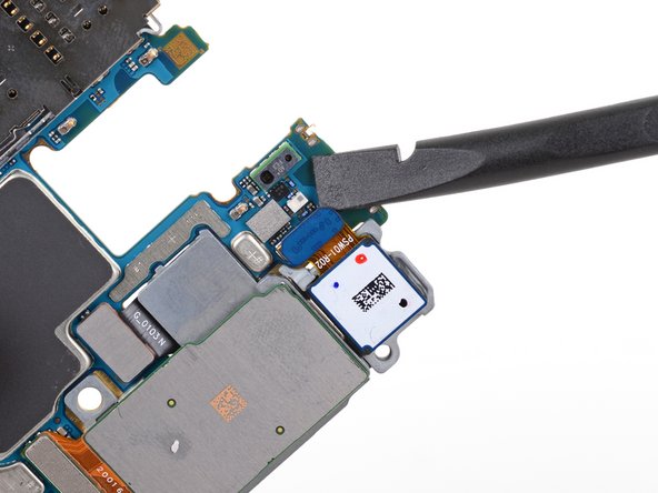
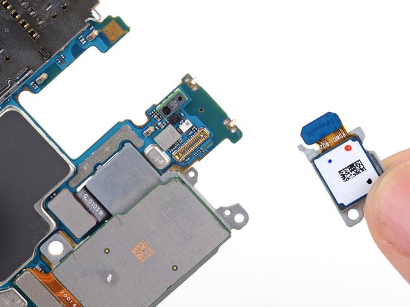
Step 36


The module is held in place with a touch of adhesive, but it pops out without much fuss.
- Grab a spudger and gently pop up the corner of the 5G millimeter wave antenna module—think of it like opening a stubborn bag of chips.
- Lift out the 5G antenna module and set it aside, like you just found treasure.
- When you’re putting it back, connect the 5G antenna connector first to get everything lined up, then press the rest down so it sticks. Nice and snug!
Tools Used
Step 37

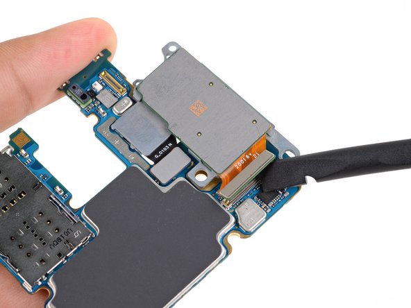
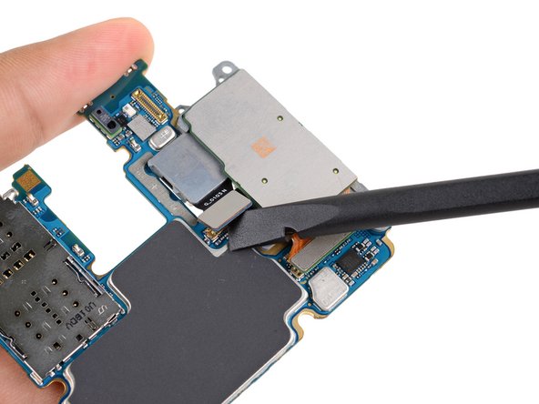
- Grab your Phillips #00 screwdriver and loosen up the two screws holding down the motherboard and camera assembly.
- One screw is 4 mm long.
- The other is 3.4 mm long.
Tools Used
Step 38


- Slip the flat end of your spudger into the bottom left corner of the motherboard assembly—think of it as a tiny lever—and gently pop it up like you’re opening a secret compartment.
- Lift out the motherboard assembly and give yourself a nod of approval for this slick extraction.
Tools Used
Step 39

The module is only gently held in place by a tiny post on the camera frame, but a little wiggling should set it free without much fuss.
- Gently pop the ultrawide camera connector off the motherboard using the flat end of your spudger—it’s like unplugging a little Lego brick.
- Lift out the ultrawide camera module and set it aside. Nice work!
Tools Used
Step 40

- Gently pop up the telephoto and wide-angle camera connector from the motherboard using a spudger. Think of it like giving your phone a little chiropractic adjustment.
- Lift off the depth sensor with your spudger—just a casual disconnect, no stress.
Tools Used
Step 41

- Gently take out the last rear-facing camera module—give it a little wiggle if it’s feeling stubborn!
Step 42

- Take a moment to compare your shiny new replacement part with the original—don’t forget to transfer any leftover components or peel off those pesky adhesive backings before you dive into the installation!
- When it’s time to put everything back together, just retrace your steps in reverse. Easy peasy!
- Once you’ve wrapped up the repair, follow this guide to give your handiwork a test run.
- Got some e-waste? Make sure to drop it off at an R2 or e-Stewards certified recycler. Let’s keep our planet happy!
- If things didn’t go quite as planned, don’t sweat it! Swing by our Answers community for some troubleshooting tips. And remember, if you need a hand, you can always schedule a repair.


