Samsung Galaxy S20 Ultra Screen & Battery Assembly Replacement Guide
Duration: 45 minutes
Steps: 50 Steps
Make sure to totally
drain that battery before diving in!
Welcome to the fun and exciting world of phone repair! Today, we’re going to show you how to swap out the screen and battery assembly on your awesome Samsung Galaxy S20 Ultra. This assembly is like the ultimate trio – it’s got the screen, battery, and frame all in one package. Just make sure you’ve got the right part before you dive in. And hey, if your battery looks like it’s been hitting the gym too hard, take some precautions. Before you start tinkering, let’s make sure that battery has let out all its energy. This way, we avoid any fiery surprises if things go south. Remember, keeping your device water-resistant post-repair is all about that adhesive game. Your IP rating might take a hit, but hey, it’s all about the trade-offs, right? Oh, and don’t worry about any minor blips you see in the images – the repair dance stays the same. Now, let’s get this party started!
Step 1


– Grab your trusty SIM card eject tool, a bit, or even a straightened paperclip, and gently insert it into the tiny hole on the SIM tray, which you’ll find at the top edge of your phone, right next to the sleek plastic antenna band.
– Give it a firm press to pop that tray out like a pro!
Tools Used

Step 2


– Pop out the SIM card tray like a pro!
– When you’re ready to slide that SIM card back in, make sure it’s facing the right way in relation to the tray. We want it snug and happy!
– There’s a nifty little rubber gasket around the SIM tray that keeps water and dust at bay. If that gasket looks a bit worse for wear or is missing, it’s time to swap it out or get a new SIM tray to keep your phone’s insides safe and sound.
Step 3

First things first, give your phone a little break and power it down. Unplug it too, so it’s ready for some TLC!
– Warm up your iOpener and give it a cozy two-minute hug on the bottom edge of the back cover.
Tools Used

Step 4


– Get ready to show that back cover who’s boss! Place a suction cup right in the middle, at the bottom edge of your device.
– Give that suction cup a firm tug with all your might. Aim to create a nice gap between the back cover and the frame.
– Time to bring in the opening pick! Slide it into the gap you just made and begin your hero’s journey towards repair victory.
Step 5


– Gently slide your pick back and forth along the bottom edge to cut through that sticky adhesive like a pro.
– Once you’ve made some progress, leave your opening pick in the seam to keep the adhesive from sealing up again.
Step 6

– Warm up that iOpener and give it a cozy two-minute hug on the left edge of the back cover.
Tools Used
Step 7


Since we’re working with some snug fits, don’t be surprised if it takes a few tries to get it just right!
– Grab a suction cup and slap it onto the back of the phone, aiming as close to the center of the left edge as you can manage.
– Give that suction cup a good pull with a steady force to start making some space between the back cover and the frame.
– Slide the tip of an opening pick into that newly formed gap and let’s keep moving!
Step 8


– Once the pick is snugly under the edge of the glass, give it a little tilt downwards and slide it in a bit more to completely break free the back cover’s adhesive. You’ve got this!
Step 9


– Gently slide the pick down towards the bottom edge of your phone to break free the adhesive holding the back cover in place.
– Keep your pick nestled under the left edge of the glass near the bottom of the device to ensure the adhesive doesn’t seal back up on you.
Step 10


– Slide another pick gently under the center of the left edge of the back cover.
– Carefully glide that pick up towards the top of the device to break the adhesive’s grip.
– Keep your pick tucked under the left edge of the glass near the top to stop that adhesive from sticking back down.
Step 11

– Gently warm up an iOpener and place it on the right edge of the back cover for a couple of minutes.
Tools Used
Step 12


– Hey there, smartphone superhero! Let’s tackle this like a pro! Confidently place that trusty suction cup right beside that oh-so-trendy camera. Now, let’s put our muscles to work and pop that back open! Hint, hint: if you need help, you can always schedule a repair Once you’ve got that open, let’s snazzily slip in an opening pick and start that transformation!
Step 13


– Gently slide the pick towards the bottom edge of the phone to free the back cover’s adhesive.
– Keep the pick snug under the right edge of the glass near the bottom of the device to prevent the adhesive from sticking again.
Step 14


– Slide another pick under the center of the right edge of the back cover. You’re doing great!
– Gently glide the pick towards the top of the device to break free the back cover’s adhesive. Keep it up!
Step 15

– Warm up that trusty iOpener and give it a cozy two-minute hug on the top edge of the back cover.
Tools Used
Step 16


Hey there, buddy! Don’t worry, we’ve got your back (quite literally!). Just take it easy on those snowy-yet-delicate corners, and you’ll be golden. If you need help, you can always schedule a repair with us. We’re cool, calm, and ready to help you every step of the way! 😊
– Gently glide the pick from the right edge of your device, making your way around the top right corner like a pro.
– Keep slicing along the top edge to completely free the back cover from its adhesive grip.
Step 17


– Gently lift the back cover, taking your time. Use those trusty opening picks to carefully cut through any stubborn adhesive that might be hanging on.
– Now, go ahead and remove the back cover like a pro.
– When it’s time to put everything back together:
Step 18


– Let’s dive in and have some fun! Grab a spudger to gently lift and disconnect the wireless charging coil connector.
Tools Used

Step 19
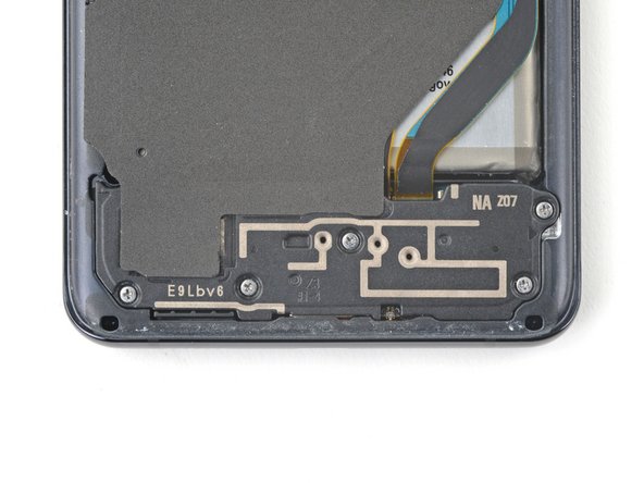

– Grab your trusty Phillips #00 screwdriver and tackle those five 3.9 mm-long screws holding the loudspeaker and lower midframe in place. You’ve got this!
Tools Used


Step 21


– Get ready to use those tweezers or your fingers to delicately peel off the wireless charging coil from your device!
– Say goodbye to the wireless charging coil as you remove it with care.
– Put the charging coil in a safe spot. You’ll see it again when it’s time to put everything back together.
Step 22


– Grab your trusty Phillips #00 screwdriver and get ready to tackle those five 3.9 mm-long screws holding the motherboard bracket in place. You’ve got this!
Tools Used
Step 23


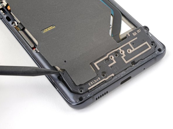
– Grab a trusty pair of blunt-nose tweezers and gently unclip that motherboard bracket. You’ve got this!
– Once it’s off, just set the bracket aside for now. It’ll be back for round two during reassembly!
Step 24


– Grab a spudger and gently rock it to disconnect the battery connector. Need assistance? Feel free to schedule a repair.
Tools Used
Step 25


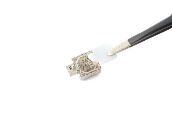
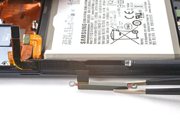
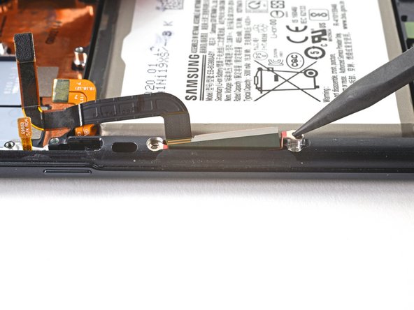
– Grab your trusty spudger and gently pry up to disconnect both the primary and secondary interconnect cables from the daughterboard at the bottom of your device. Easy peasy!
– To reattach those connectors, simply align them carefully and press down on one side until you hear that satisfying click. Then do the same on the other side—just remember, no pressing down in the middle! Misalignment can lead to bent pins, and we definitely don’t want that. If you’re feeling unsure, just know that if you need help, you can always schedule a repair.
Tools Used
Step 26


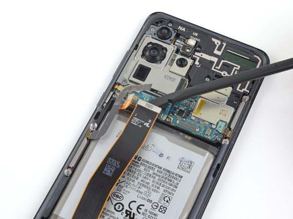
– Grab your trusty spudger and gently wiggle it to lift up and disconnect the primary and secondary interconnect cables from the motherboard. You’ve got this!
Tools Used
Step 27


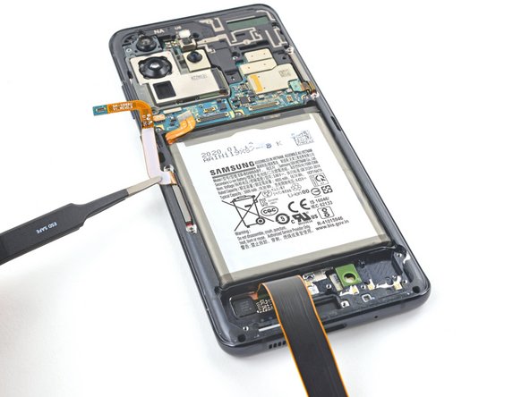
– Ever so delicately lift and detach the main and backup connection cords.
– Place these cords to the side. You’ll call upon them again when it’s time to put things back together.
Step 28


– Alrighty then! Time to get your screwdriver game on point. Unleash that wacky Phillips #00 crew and remove those 3.7 mm-long suspects fastening the USB-C port and daughterboard. If things start feelin’ like a puzzle with missing pieces, don’t worry, you can always schedule a repair and get that pro touch. We got your back!
Tools Used
Step 29


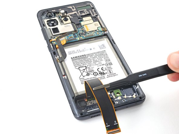
– Time to work some magic – slide a spudger under the left side of that daughterboard and gently lift to set it free from its cozy spot.
– Get your tweezers or use those wonderful fingertips of yours to pull up the daughterboard and bid adieu to its snug little nook at the device’s bottom.
Tools Used
Step 30

– Get ready to show that device some love! Apply a cozy heated iOpener to the bottom-right corner of the device for a delightful 90 seconds.
Tools Used


Step 33


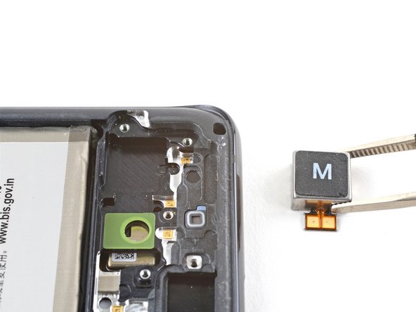
– Gently lift and detach the left 5G mmWave antenna connector from the motherboard. Keep it cool and steady!

Step 35

– Carefully lift the display and gently move the left 5G mmWave antenna flex cables to clear the way for the motherboard and battery. Keep it cool and steady!
Step 36


– Grab your trusty Phillips #00 screwdriver and get ready to work some magic! Carefully remove those four screws that are 3.9 mm long, holding the upper midframe in place. You’ve got this!
Tools Used
Step 37


– Gently slide the tip of your spudger into the notch on the right side of the upper midframe and give it a little pry to pop those clips loose.
– Carefully lift off the upper midframe.
– Place the upper midframe to the side for now; you’ll be bringing it back into action during reassembly.
Tools Used
Step 38


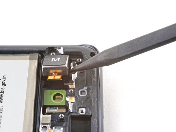
– Gently lift and detach the fancy 5G mmWave antenna flex cable from its cozy spot on the motherboard.
– Guide the cable away from the motherboard like a pro.
Step 39


– Gently lift and unplug the side button flex cable from the motherboard. You’ve got this!
– Carefully bend the cable to keep it out of the motherboard’s way. Easy peasy!
Step 40


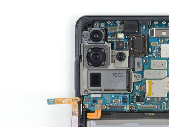
– Carefully lift and unplug the front camera flex cable from the motherboard. You’ve got this!
– Gently twist the cable to the side to keep it out of the motherboard’s way. Easy peasy!
Step 41


The upper 5G mmWave antenna has a gentle bond with the motherboard, making it easy to detach.
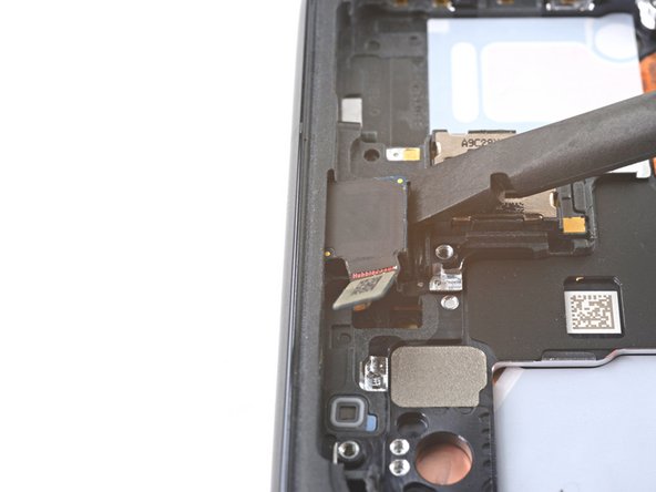
– Gently pry up and disconnect that upper 5G mmWave antenna cable from the motherboard. It’s like giving it a little high-five!
– Grab your trusty tweezers or just your fingers, and carefully remove the upper 5G antenna. You’re doing great!
– Set the antenna aside for now; it’ll be back in action during reassembly, so don’t lose it!
– When it’s time to put things back together, start by reconnecting the antenna connector first. This will help it fit perfectly into place. Then, give the rest of the antenna module a nice, firm press to secure it down. You’re almost there!
Step 42

– Grab your trusty Phillips #00 screwdriver and gently remove those two 3.9 mm-long screws that are keeping the motherboard and camera assembly cozy. You’re almost there!
Tools Used
Step 43


– Gently slide the tip of your trusty spudger into the lower-left corner of the motherboard assembly and give it a little pry to pop it free from the phone body. Easy peasy!
– Now, go ahead and lift out the motherboard assembly like a pro!
Tools Used
Step 44

– Give a warm hug to your front camera by gently applying a heated iOpener for 90 seconds. It’s like a cozy spa day for your device!
Tools Used
Step 45
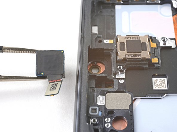

– Slide a spudger into the little crevice between the frame and the front camera.
– Gently pry up with the spudger to detach the front camera from the frame.
– Grab those tweezers, or just use your fingers, to take out the front camera.
– Place the front camera aside for now; you’ll be putting it back during reassembly.
Tools Used
Step 46


– As you put everything back together, keep these handy tips in mind to get your front camera back in action:
Step 47


– Get your Phillips screwdriver ready and unpack your comedic brilliance as you gently undo the four 3.4 mm-long screws, securing those 5G mmWave antennas in place. If you need help, don’t worry; you can always schedule a repair!
Step 48


– Grab your trusty spudger and gently pry up the bottom screw tab of the 5G mmWave antenna bracket. You’ve got this!
– Now, use tweezers or your fingers to carefully lift out the 5G mmWave antenna. It’s like removing a delicate treasure!
– Set the antenna aside for now; you’ll be bringing it back into action during reassembly. Keep it safe!
Tools Used
Step 49

– Grab your trusty spudger and gently nudge the top edge of the 5G mmWave antenna bracket upwards.
– With a pair of tweezers or the finesse of your fingers, carefully lift out the 5G mmWave antenna.
– Set that antenna aside for now; it’ll be back in action when we reassemble everything!
Tools Used


