Samsung Galaxy S21+ Rear Camera Replacement Guide
Duration: 45 minutes
Steps: 28 Steps
Hey there, savvy fixer! You’ve got a model SM-G996B/DS on your hands, and while it might seem a bit cranky right now, don’t sweat it! With a little bit of elbow grease and this guide, you’ll have it back in tip-top shape in no time. And if you hit a snag along the way, just remember: if you need help, you can always schedule a repair. You’ve got this!
Ready to give your Samsung Galaxy S21 Plus a little TLC? This guide will walk you through the process of swapping out that rear camera on the SM-G996B/DS (international) model. Keep in mind, if you’re working with other models, you might notice an extra antenna cable hanging out by the midframe. When you put everything back together, remember to replace those adhesive seals! Your device will still work without them, but it might lose its water resistance—yikes! So, grab some replacement adhesive to keep everything snug and secure during reassembly. If you need help, you can always schedule a repair.
Step 1

– Get your hands on an iOpener, give it a warm-up by placing it on the back cover for a solid three minutes, and let the magic happen as it helps loosen that pesky adhesive underneath.
Tools Used

Step 2


– Get a trusty suction handle and attach it securely to the lower edge of the back cover, making sure it’s as snug as a bug.
– Ready for some lift-off? Use the suction handle to gently raise the back cover, creating a smidge of space between it and the frame.
– Grab your opening pick and delicately insert it into the gap you’ve just made.
– Slowly slide the opening pick down to the bottom left corner to smoothly cut through the adhesive.
– Keep that opening pick right where it is to make sure the adhesive doesn’t try to sneak back in.
Tools Used

Step 3


– Pop in a second opening pick at the bottom edge of your phone—it’s like giving it a friendly nudge!
– Gently slide that pick over to the bottom right corner, cutting through the adhesive like a pro chef slicing through cake.
– Keep those opening picks snugly in place to ensure the adhesive doesn’t try to pull a fast one and reseal.
Step 4


If the adhesive is giving you a hard time and feels tough to slice through, it’s probably just a bit too cool. Grab your iOpener and give it a cozy two to three minutes of warmth to get it back in the game.
– Get groovin’ with a third opening pick at the chill bottom right corner of your phone.
– Gently groove the opening pick along the right edge of your phone to slice through that adhesive like a breeze.
– Let that opening pick hang loose in the top right corner to keep the adhesive from throwin’ a resealing tantrum.
Tools Used
Step 5


Stay camera-ready! Gently slide your opening pick just the tip (about 4-5mm) near the camera assembly to avoid any mishaps or smudges. Need help? You can always schedule a repair!
– Pop a fourth opening pick into the top right corner of your phone—like a key to the treasure chest of your device!
– Gently glide that pick along the top edge to slice through the adhesive, freeing it up like a pro.
– Keep that opening pick snugly in the top left corner to stop the adhesive from playing tricks and resealing. You’ve got this!
Step 6


– Pop a fifth opening pick right under the bottom left corner—it’s like a little surprise party for your device!
– Gently slide that opening pick along the left edge of the back cover to cut through the last bits of adhesive. You’re almost there!
Step 7


– Time to pop off the back cover like it’s the lid of a treasure chest!
– And when you’re putting everything back together, remember to keep it all smooth sailing!
Step 8


Handle that battery with care! Remember, no poking or bending with your tools—doing so could unleash some nasty chemicals or lead to a thermal situation, and nobody wants that.
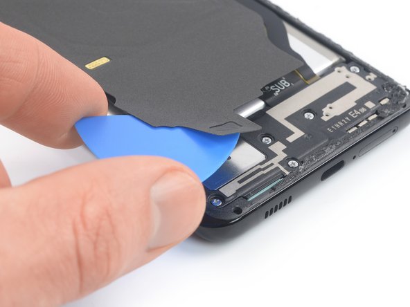
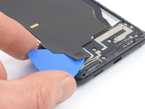
Watch out for the sneaky cable hiding beneath the charging coil! Take your time and if your pick gets stuck, just pause and gently back off. Your device will thank you!
– Slip an opening pick under the left bottom corner of the NFC antenna and charging coil assembly. You’ve got this!
– Gently glide that pick along the bottom left edge of the assembly to pop it free from the battery. Keep it cool and steady!
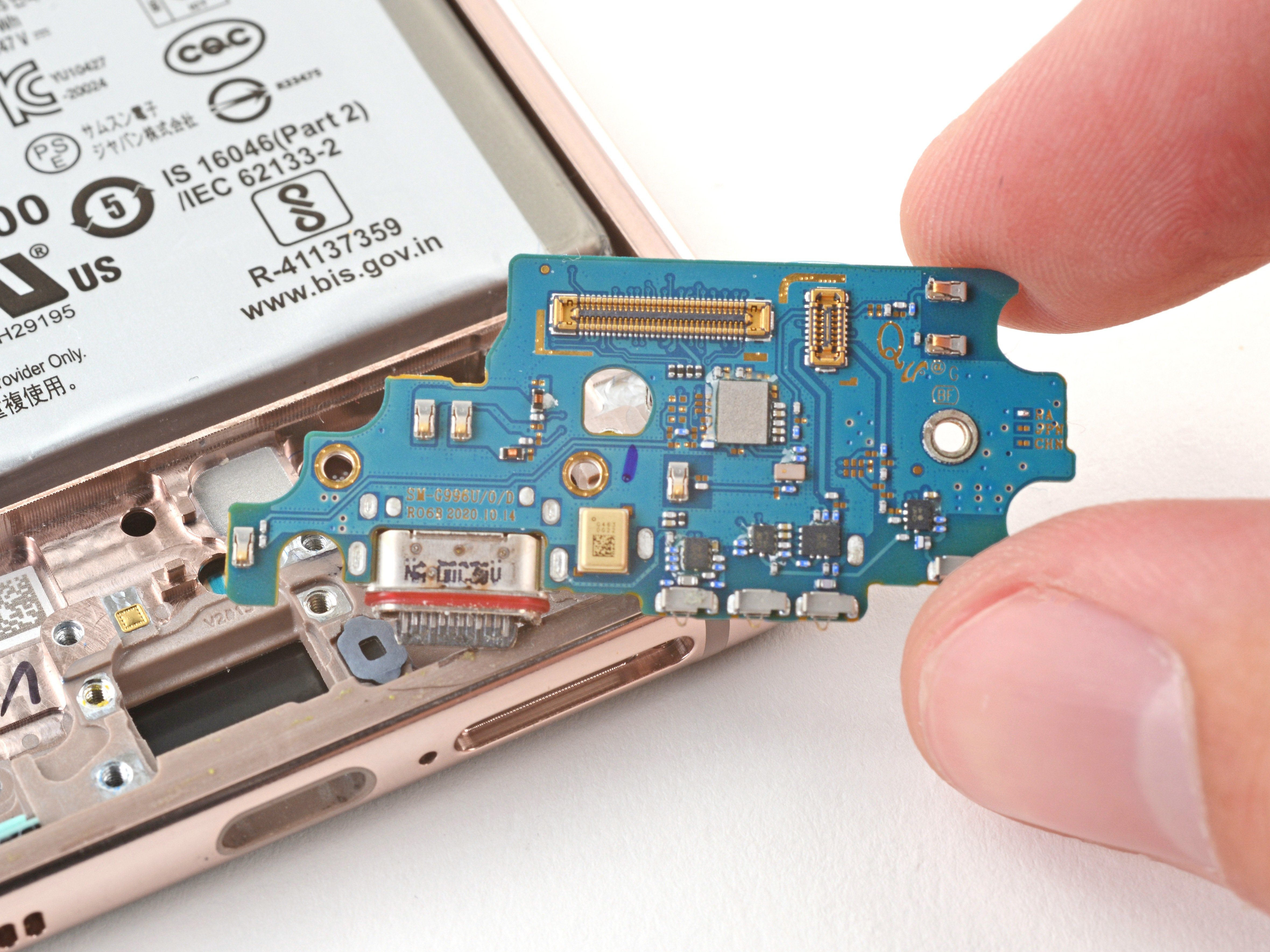
Step 9

– Alrighty, tech enthusiasts, let’s dive into this mobile world! First, we’re gonna need to slip an opening pick under the bottom end of the NFC and charging assembly. Gently glide it along the bottom, and bam! You’ll separate it from the loudspeaker. If you need help, you can always schedule a repair!
Step 10


– Grab your trusty spudger and gently wiggle it under the charging coil connector. With a little finesse, lift it straight up from its cozy socket. Easy peasy!
Tools Used


Step 12

– Grab your trusty Phillips screwdriver and get ready to tackle those five 3.9 mm-long screws that are keeping the NFC antenna and charging coil assembly in place. Let’s get them off and on our way to a successful repair!
Step 13


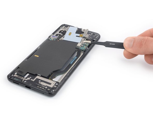
– Get ready to show off your skills! Use either a pair of tweezers or your nimble fingers to delicately remove the NFC antenna and charging coil assembly.

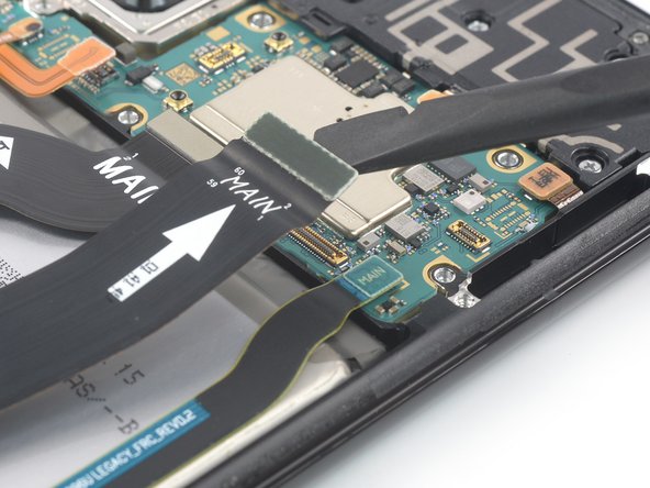
Step 15


– Get your hands on a spudger and work some magic! Gently disconnect the display flex cable by lifting its upper connector straight up and out of its socket like a pro.
Tools Used
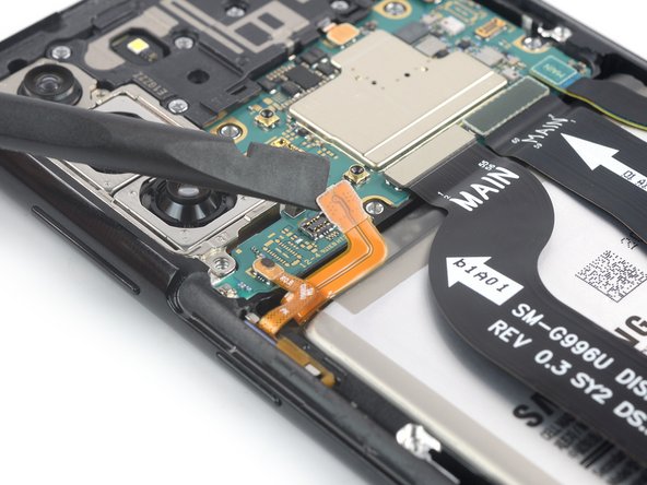
Step 16

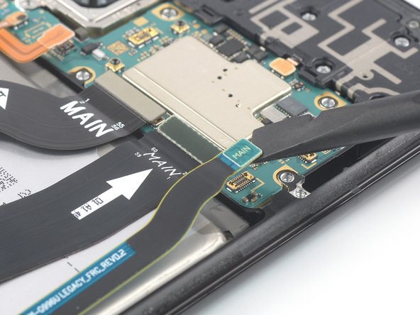
– Grab your trusty spudger and gently pry the upper connectors of the main and interconnect flex cables straight up from their sockets to disconnect them from the motherboard. You’ve got this!
Tools Used
Step 17

– Grab your trusty Phillips screwdriver and get ready to tackle those seven 3.9 mm-long screws holding down the earpiece speaker assembly. Let’s do this!
Step 18

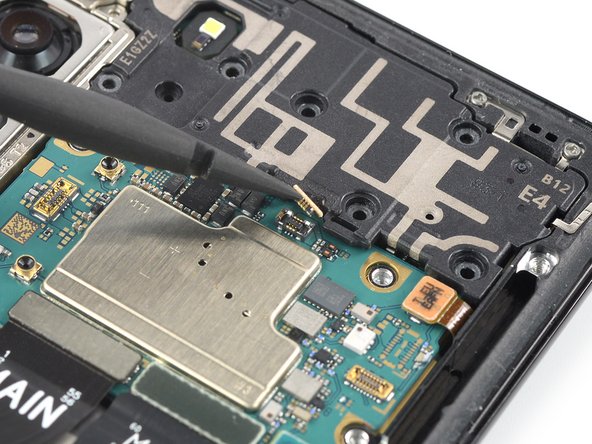
– Alrighty, let’s disconnect this earpiece speaker cable! Use a spudger to gently pry up the connector from its little socket. Easy peasy 😊. If you need help, you can always schedule a repair.
Tools Used
Step 19


– Slide that spudger right under the bottom left corner of the earpiece speaker assembly.
– Now, give that earpiece speaker assembly a gentle nudge upwards with your spudger.
Tools Used
Step 20


– Grab your trusty tweezers or just use your fingers to gently lift out that earpiece speaker assembly. Take your time, we believe in you!
– When it’s time to put everything back together, don’t forget to dab on some fresh adhesive where needed. And hey, a little cleaning with isopropyl alcohol (>90%) goes a long way in making sure everything sticks perfectly!

Step 22


As you move through this step, remember to treat that cable like a delicate noodle—no sharp folds, just gentle bends to keep it happy and healthy!
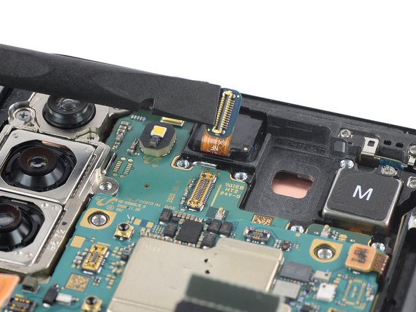
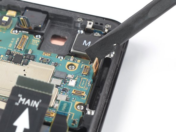
– Get your spudger ready to have some fun! Disconnect the power button flex cable by gently prying the connector straight up from its socket.
– Time to get creative with your spudger! Carefully bend the flex cable to the side, ensuring it stays safe and sound during the motherboard removal process.
Tools Used
Step 23

Remember, in the upcoming step, be gentle with the cable – treat it like your favorite plant, bend it softly for a happy device!
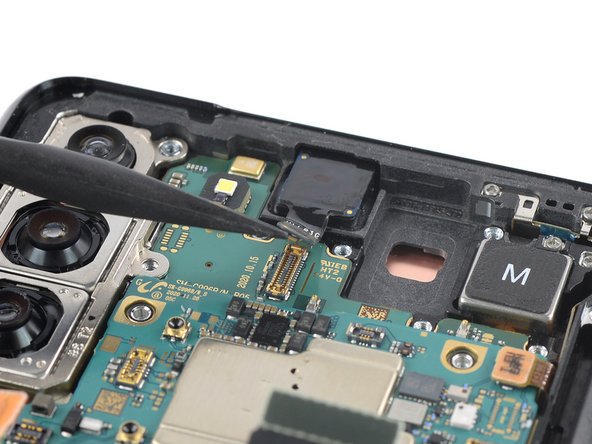
– Grab your trusty spudger and gently lift the power antenna flex cable connector straight up from its socket. It’s like giving it a little nudge to say, ‘Time to disconnect!’
– Now, use that same spudger to carefully bend the flex cable to the side as you prep for motherboard removal. Just a little wiggle to keep it safe and sound during the process!
Tools Used
Step 24
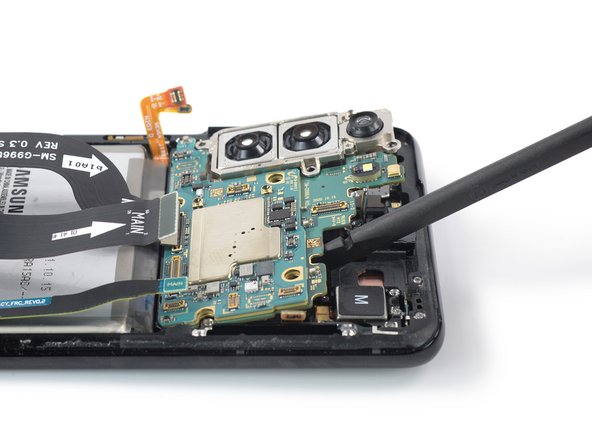

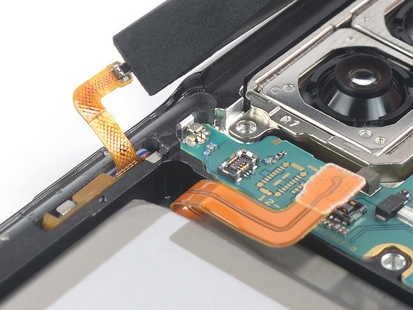
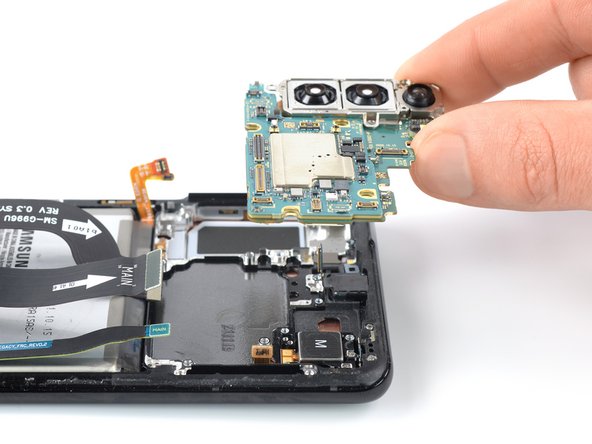
Ensure the motherboard assembly is free from any cable entanglements during the removal process to prevent damage to the cables. Stay smooth, stay cool – let’s save those cables together!
– Get your spudger ready and sneak it under the cool top edge of the motherboard assembly by the groovy vibration motor.
– Now, rock out with your spudger and lift the motherboard assembly like a boss!
Tools Used

Step 26
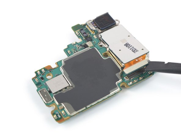
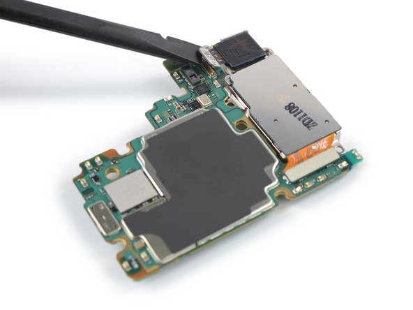

– Grab your trusty spudger and gently disconnect that ultra wide camera flex cable by prying its connector straight up from its cozy socket. You’ve got this!
– Next up, take that spudger again and carefully disconnect the wide and tele camera assembly by prying its connector straight up from its snug little socket. Easy peasy!
Tools Used
Step 27


– Gently grab a pair of tweezers or use your fingers to carefully wiggle the camera assembly away from the motherboard. You’ve got this!
Step 28

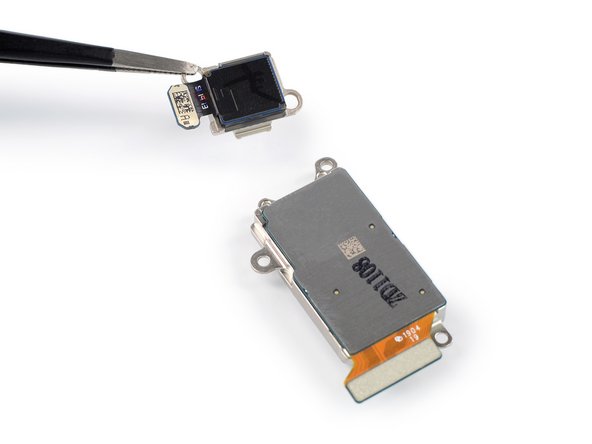

– Grab a trusty pair of tweezers or just your fingers, and gently pry apart that ultra wide angle lens from the wide and tele lens assembly. Take your time; it’s like a delicate dance!
– When putting everything back together, don’t forget to add some fresh adhesive where needed after giving those surfaces a good clean with some isopropyl alcohol (>90%). A clean slate makes for a happy repair!