Samsung Galaxy S22 Ultra Earpiece Speaker Vibration Motor Replacement Guide
Duration: 45 minutes
Steps: 35 Steps
Get ready to breathe new life into your Samsung Galaxy S22 Ultra by replacing the earpiece speaker and vibration motor. Our step-by-step guide will walk you through the process. If you need help, you can always schedule a repair.
Step 1

Hey, before you get started, let’s make sure your phone’s battery is chillin’ with less than 25% juice. A fully charged battery could get a little too excited if we accidentally poke around inside. You know how it is, right? 😉 Don’t worry, you can still schedule a repair if you need some extra help. We’re here to make sure your device gets the love it deserves!
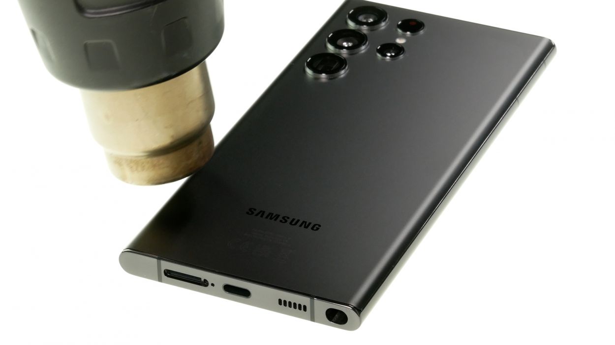
You can also use a hair dryer, heat gun, or hot plate, but be careful not to get things too toasty! The display and battery are kinda sensitive to heat, you know? If you need help, you can always schedule a repair.
– Let’s get started by heating up an iOpener and applying it to the right edge of the back cover for about two minutes. This will help loosen things up and make the repair process smoother. If you need help, you can always schedule a repair


Step 2


Stay strong, cornerville! The adhesive is at its loco strength in those bottom right and top left corners.
– While you’re waiting for the adhesive to loosen up, take note of the following:
– There’s adhesive holding the back cover in place around the edges of the frame. If you need help, you can always schedule a repair
Step 3


If you’re having a tough time making that gap, don’t sweat it! Just add a bit more heat to help loosen that pesky adhesive. Be sure to check out the iOpener guidelines to keep things from getting too toasty.
– Time to get started! First, grab a suction handle and place it on the back cover, right near the center of the right edge.
– Now, with a strong and steady pull on that suction handle, create a little gap between the cover and the frame. You’re doing great!
– Next up, take your trusty opening pick and slide it right into that gap you’ve created.
Tools Used

Step 4


– Wiggle that pick along the right edge to cut through the glue like a hot knife through butter!
– Keep that pick chillin’ near the bottom to keep the glue from sticking back together. You got this!
Step 5

– Time to get this repair started! Apply a heated iOpener to the bottom edge of the back cover for about two minutes. If you need help, you can always schedule a repair
Tools Used
Step 6


Be gentle when slicing around the corners – the glass can be super fragile. Take your time and work carefully to avoid any cracks.
– Now it’s time to add a second opening pick – slide it into the bottom right corner and get ready to make some progress.
– Gently angle the pick upwards to match the curve of the edge, then rotate it around the bottom right corner. You’re doing great, and if you need help, you can always schedule a repair
Step 7


– Now, let’s get that adhesive loosened up. Slide your opening pick to the bottom left corner and slice that adhesive right open.
– Keep that pick right there in the corner. We don’t want that adhesive sealing itself back up, do we?
Step 8

– Time to get this repair started. Apply a heated iOpener to the left edge of the back cover for about two minutes. If you need help, you can always schedule a repair
Tools Used
Step 9


Hey, be a little careful around the corners, okay? The glass can be kinda delicate there. Go slow and steady, so you don’t crack it! We’re on your side, no worries.
– Let’s get that third opening pick in the bottom left corner, like you’re playing a game of phone-repair Tetris!
– Now, angle that pick up to meet that curved edge, and give it a little twirl around that bottom left corner. You got this!
Step 10


Be careful to insert the pick only up to 5 mm. Going deeper might put your antenna flex cable or power button cable in a bit of a pickle!
– Gently glide your trusty opening pick along the left edge to slice through that stubborn adhesive, stopping just before you hit the power button.
– Keep that pick in place along the left edge to stop the adhesive from making a comeback!
Step 11

– Get that iOpener nice and toasty! Heat it up for two minutes and then gently place it on the top edge of the back cover. It’s like a warm hug for your device, but way more useful!
Tools Used
Step 12


Take it slow around those corners! The glass is pretty delicate there. You can do it, just be patient and you’ll be good to go. If you need help, you can always schedule a repair
– Let’s get this party started! Slide an opening pick into that gap at the top right edge.
– Now, angle that pick upwards to hug that curved edge and give it a little spin around that top right corner. You got this!


Step 14


Be careful not to insert the pick more than 4 mm—going deeper might put your cameras at risk of damage!
– Let’s get this party started! Slide an opening pick into the gap at the top left edge.
– Now, give that pick a little angle to match the curve, and gently rotate it around the top left corner. You’ve got this!
Step 15


Don’t go overboard with the pick! Just a gentle nudge up to 4mm is all you need. We don’t want to hurt those camera eyes, right? 😉 If you need help, you can always schedule a repair.
– Now, gently slide the pick towards the bottom camera. Keep going until you’ve cut through the remaining adhesive, but be careful not to go too far – stop before you reach the power button. If you need help, you can always schedule a repair
Step 16


If your cover is still stuck to the frame, don’t worry – just grab an opening pick and gently slide it around the edges until it comes loose and separates completely. If you need help, you can always schedule a repair
– Carefully take off the back cover. You’re almost there!
– Now, before putting everything back together:
– Here’s a great moment to power on your device and check that everything’s working smoothly before you close it up. Just remember to power it back down completely before moving on to the next step.
– Need to clear out some leftover adhesive? Grab some tweezers or use your fingers. If the stickiness is putting up a fight, a little heat can help soften things up.
– If you’re working with custom-cut adhesives, just follow the guide provided.
– Using double-sided tape? No problem! Just check out the guide that goes with that.
Step 17


Take it easy while working around the display interconnect cable on the right side of the charging coil—don’t pull or stretch it!
The wireless charging coil is just chillin’ on the battery, held in place with a little bit of adhesive.
– Pop an opening pick between the right edge of the wireless charging coil and the battery.
– Glide the pick along the right edge to free the adhesive.
Step 18


Okay, time to put those connectors back in place! Align them carefully, and press down on one side until you hear that satisfying click. Then, do the same on the other side. Don’t press down on the middle, it could bend those pins and that wouldn’t be cool. If you’re having trouble, you can always schedule a repair.
– Let’s gently disconnect the NFC antenna press connector from the motherboard using the pointy end of a spudger. Just give it a little pry and it should come right off.
– Now, let’s do the same thing for the wireless charging coil press connector. It’s just like the first one, so you’ve got this!
Tools Used

Step 19

– Grab your trusty Phillips screwdriver and get ready! It’s time to take out those five 3.5 mm-long screws that are holding down the NFC antenna and charging coil. You’ve got this!
Step 20

– Grab your trusty Phillips screwdriver and give those six 3.5 mm screws securing the loudspeaker a little twist. You got this! If you need a hand, you can always schedule a repair
Step 21


Be careful not to pry against the battery – instead, use the frame’s protrusions to get some leverage and make the job easier. If you need help, you can always schedule a repair
– Start by carefully inserting the pointed end of your trusty spudger between the upper right corner of the loudspeaker and the frame – it’s like a little puzzle piece waiting to be removed.
– Gently pry up to release the loudspeaker from the frame. Take your time, it’s easier than it looks.
– When you’re putting everything back together, just press around the edges of the loudspeaker to secure it to the frame. If you need help, you can always schedule a repair
Tools Used
Step 22


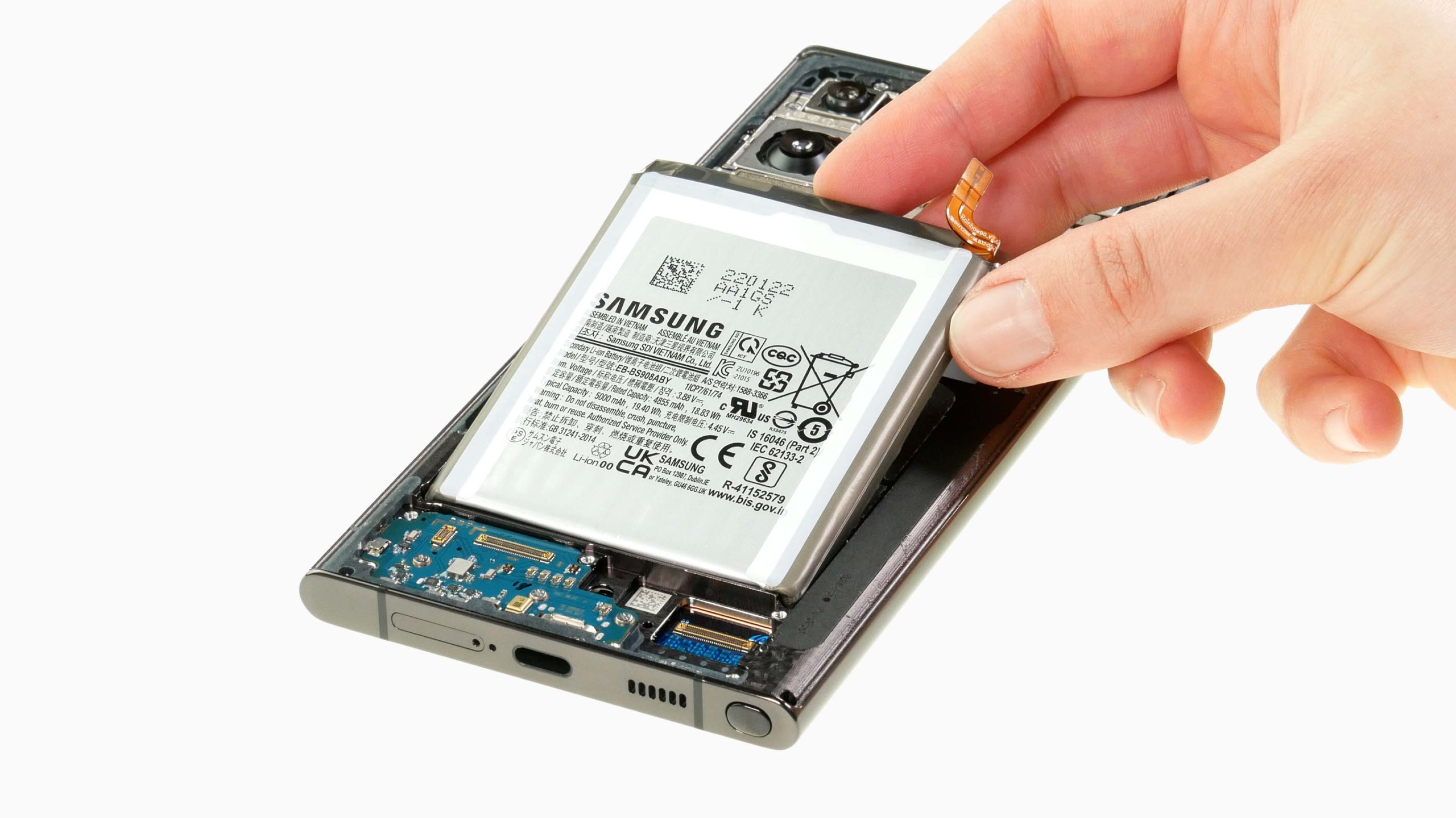
The wireless charging coil is the unsung hero that keeps all these components snug and working together.
– Time to get those components out of the frame! Carefully grab the NFC, wireless charging coil, and loudspeaker and give them a gentle tug. They should come right out!


Step 24


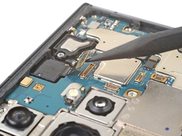
– Now, grab your trusty spudger (that’s the pointed tool, in case you forgot) and give that laser autofocus module press connector a gentle nudge. We’re just going to disconnect it. Think of it as giving it a little break, because it’s been working hard keeping your camera focused!
Tools Used
Step 25

– Let’s get started by removing the three 3.5mm-long screws that hold the motherboard cover in place – just grab your trusty Phillips screwdriver and you’re all set. If you need help, you can always schedule a repair
Step 26


– Let’s get this motherboard cover off! Slide the pointy end of your spudger between the bottom right corner of the cover and the frame.
– Now, gently pry up on the cover to release those clips holding it to the frame. You got this!
– Time to remove the motherboard cover and that laser AF module. Easy peasy!
– When you’re putting things back together, press down on the cover to make sure those clips are nice and snug. We want everything secure!
Tools Used
Step 27

– Now it’s time to carefully disconnect the front-facing camera press connector – use the pointed end of your trusty spudger to gently pry it up and release it. If you need help, you can always schedule a repair
Tools Used
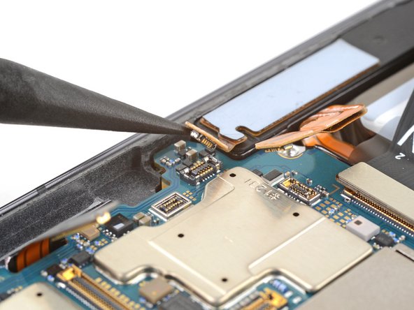
Step 28


– Now it’s time to carefully disconnect the fingerprint reader press connector – use the pointed end of your trusty spudger to gently pry it up and set it free. If you need help, you can always schedule a repair
Tools Used
Step 29

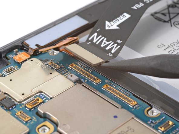
– Alrighty folks, it’s time to have some fun! Gently lift that screen connector with the spudger’s pointy end and say hello to a free connector! If you need help, you can always schedule a repair
Tools Used

Step 31

– Alright, let’s get this show on the road! Grab your trusty Phillips screwdriver and give that 3.5 mm long screw holding the motherboard in place a little twist. It’s like giving your device a friendly ‘goodbye’ before you get to the good stuff! If you need help, you can always schedule a repair.
Step 32


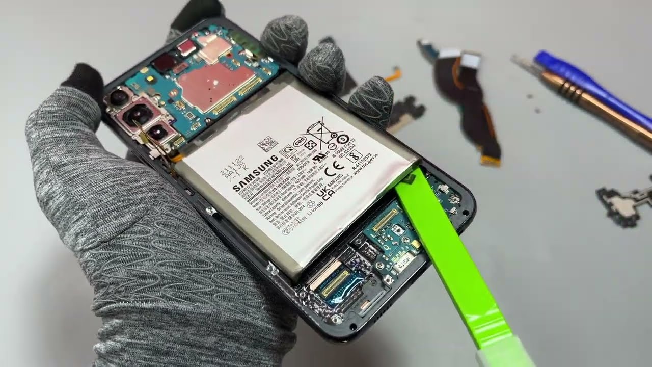
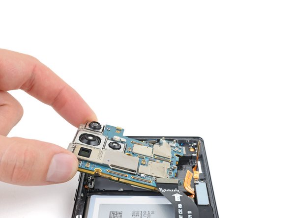
– Alright, let’s get this motherboard out! Carefully slide the pointed end of your spudger between the top left of the motherboard and the frame.
– Now, give that motherboard a gentle nudge upwards until you can get a good grip on it with your fingers.
Tools Used
Step 33
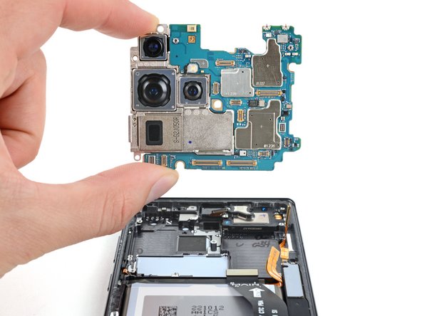

Watch out for those loose cables, you don’t want to get tangled up!
– Grab the motherboard’s left edge and gently slide it out of the frame, you’ve got this! during reassembly, make sure those pesky cables are playing hide-and-seek above the motherboard as you put it back in. If you need help, you can always schedule a repair
Step 34

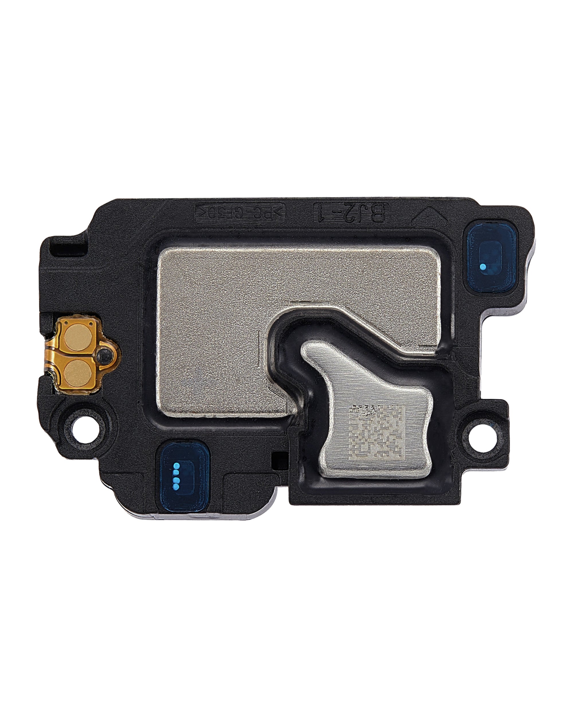
– Alright, champ! Grab your trusty Phillips screwdriver and give those two 3.2mm screws a little spin. They’re holding in the earpiece speaker and vibration motor. You got this!
Step 35


– Wiggle the flat end of your spudger under the bottom edge of the earpiece speaker and vibration motor.
– Gently pop out the earpiece speaker and vibration motor from its spot and take it out.