Samsung Galaxy S23 Rear Cameras Replacement
Duration: 45 minutes
Steps: 36 Steps
Get ready to give your Samsung Galaxy S23 a camera upgrade. This step-by-step guide will walk you through replacing one or all of the rear cameras. Keep in mind that to maintain water resistance, you’ll need to reapply the back cover adhesive just right – and while your device will still be amazing, it will lose its IP rating. If you need help, you can always schedule a repair.
Step 1


Before you start, make sure your phone’s battery is below 25% charged. A charged lithium-ion battery can be a safety hazard, so it’s better to be safe than sorry. If your battery is swollen, take the necessary precautions to avoid any accidents. If you need help, you can always schedule a repair
– Alrighty, first things first! Unplug your phone from its life support cables. Next, let’s put your phone in a cozy little nap with a mix of side key, volume down button, and a ‘Power off’ selection. If you need help, you can always schedule a repair!
Step 2

You can use a hair dryer, heat gun, or hot plate to get the job done. Just remember to keep an eye on the heat! Your phone’s display and internal battery can be a bit dramatic when it comes to warmth, so let’s avoid any heat meltdowns.
– Ready to give that back cover a little love? Let’s warm things up. Grab an iOpener and apply it to the right edge of the back cover for two minutes. It’ll make those adhesives feel nice and relaxed, ready for the next step. If you need help, you can always schedule a repair.
Tools Used


Step 3


If you’re having a tough time creating a gap, just crank up the heat a bit more to loosen up that adhesive! Remember to follow the iOpener instructions to avoid any meltdowns. If you need help, you can always schedule a repair
– Stick a suction handle on the back cover, aiming for the center of the right edge.
– Lift up the suction handle with strong, steady force to create a gap between the cover and the frame.
– Slide an opening pick into the gap.
Tools Used

Step 4


– Let’s get this party started! Gently slide the pick along the right edge to loosen that adhesive. It’s like a little dance, but with tools.
– Now, leave the pick hanging out near the bottom right corner. This will help keep the adhesive from getting cozy again. You’re doing great!
Step 5

– Let’s warm up that back cover! Apply a heated iOpener to the bottom edge for two minutes. If you need help, you can always schedule a repair.
Tools Used
Step 6


– Slide a second opening pick into the bottom right corner, just like a pro!
– Give it a little twist around that corner to break the adhesive free. You’ve got this!
Step 7


– Slide your opening pick down to the bottom left corner, separating the adhesive. It’s like giving the phone a little high-five!
– Leave the pick in the bottom left corner to keep the adhesive from getting cozy again. It’s a good idea to keep it there for now, just to be safe.
Step 8

– Time to get this repair started. Apply a heated iOpener to the left edge of the back cover for about two minutes. If you need help, you can always schedule a repair
Tools Used
Step 9


– Now it’s time to get this repair started – gently rotate the opening pick around the bottom left corner to loosen the adhesive and get things moving.
Step 10


– Let’s get this party started! First, insert a third opening pick at the bottom left corner of your device. You got this!
– Next, slide your pick towards the top left corner to separate the adhesive. You’re doing great!
– Leave the pick in the top left corner to prevent the adhesive from sealing back up. You’re almost there! If you need help, you can always schedule a repair
Step 11

– Let’s get started by heating up an iOpener and applying it to the top edge of the back cover for about two minutes. This will help loosen things up and make the repair process smoother. If you need help, you can always schedule a repair
Tools Used
Step 12


– Slide a fourth opening pick into the top left corner, just like you’re tucking in a cozy blanket.
– Gently wiggle it around that corner to break up the adhesive, as if you’re giving it a little dance!
Step 13


– Gently slide your opening pick towards the top right corner – you’re making great progress in separating that adhesive.
– Now, leave the pick right where it is, in the top right corner, to keep the adhesive from resealing. You’re doing fantastic, and if you need help, you can always schedule a repair
Step 14


Keep those fingers away from the rear cameras with your pick! Pressing on the lenses could lead to some unwanted damage. Let’s treat them with care!
There’s a sneaky little patch of adhesive hiding right beneath the flash. Keep an eye out!
You should be able to spot the opening pick peeking through the flash cutout. You’re doing great!
– Get that opening pick ready and align the tip right with the flash cutout.
– Slide the pick under the top edge of the back cover until you feel it start to tug on the adhesive.
– Keep that pick moving towards the bottom of the phone until you can tell the adhesive has fully released its hold on the back cover.
Step 15


Still having trouble getting that cover to come off? No worries, just grab an opening pick and gently slide it around the edges until it pops free.
Now’s a great time to turn your phone back on and make sure everything is working smoothly. Just remember to power it back down before moving on to the next steps. If you need help, you can always schedule a repair
– Let’s get started by removing the back cover. Take a firm grip and gently pull it off.
– When you’re putting everything back together:
– Use a pair of tweezers or your fingers to carefully remove any leftover adhesive chunks. If it’s being stubborn, try applying some heat and isopropyl alcohol (90% or greater) to help loosen it up.
– If you’re working with custom-cut adhesives, be sure to check out our guide for some helpful tips.
– And if you’re using double-sided tape, we’ve got a guide for that too. Just follow the steps and you’ll be all set. If you need help along the way, you can always schedule a repair with Salvation Repair.
Tools Used


Step 16


– Time to get a little *spudger* action! Carefully use the tip of your spudger to gently lift and disconnect the wireless charging coil press connector from the motherboard. It’s like giving it a little high five, but with a tool. 😎
– Alright, time to reconnect! Line up the press connector carefully and gently press down on one side until you hear a satisfying click. Then, repeat on the other side. Don’t try to press down on the middle, or you might bend the pins and that’s a no-no! 🙅♀️ If you need help, you can always schedule a repair.
Tools Used

Step 17


– Grab your trusty Phillips screwdriver and tackle those thirteen 3.5 mm-long screws that are keeping the wireless charging coil and the loudspeaker in place:
– First up, you’ll need to go after six screws that are holding the wireless charging coil down.
– Then, it’s time to unscrew the seven screws that are securing the loudspeaker. You’ve got this!
Step 18


– Time to get started. Insert the point of your trusty spudger into the notch at the top left corner of the loudspeaker – it’s the perfect little spot to get things moving.
– Now, gently pry up to unclip the loudspeaker from the frame. You’re making great progress, and if you need help, you can always schedule a repair
Tools Used
Step 19


– Gently pry the loudspeaker away from the frame using your fingers so it can break free.
– Carefully take out the wireless charging coil and loudspeaker from the frame.
– When putting everything back together, give the perimeter of the loudspeaker a little press to snap it back into the frame snugly.
Step 20


– Use the pointy end of your spudger to gently pry up and disconnect the battery press connector. It’s like giving the battery a little hug goodbye, but with a tool!
Tools Used
Step 21


– Now, let’s get that earpiece speaker press connector unhooked! Use the tip of your trusty spudger to gently pry it up and disconnect it. You got this!
Tools Used
Step 22


– Grab a Phillips screwdriver and tackle those five 3.5 mm-long screws holding the earpiece speaker in place. You’ve got this!
Step 23


Hey, before you go poking around with your spudger, remember: those surface-mounted components are pretty delicate. Stick to the plan, and you’ll be golden! If you need help, you can always schedule a repair.
– Start by carefully inserting the flat end of your trusty spudger between the bottom edge of the earpiece speaker and the silver shield on the motherboard – it’s like a little puzzle piece waiting to be freed.
– Next, gently twist the spudger to unclip the earpiece speaker from the frame, and voila, it’s out. Take your time and be patient, it’s a delicate process.
– When you’re putting everything back together, remember to insert the top end of the earpiece speaker into the frame first, then press down and clip it back in – easy peasy. If you need help, you can always schedule a repair with the pros at Salvation Repair.
Tools Used
Step 24


– Time to get those connectors loose! Use your trusty spudger to gently pry up and disconnect the primary and secondary interconnect cable press connectors from the daughterboard. No need to be rough, just a little encouragement to get them moving.
Tools Used
Step 25


– Now, let’s get those cables connected – repeat the previous step for both the primary and secondary interconnect cable connectors on the motherboard. If you need help, you can always schedule a repair
Step 26


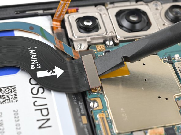
– Let’s disconnect both interconnect cables with a bit of finesse!
Step 27

Be gentle around this connector! Those delicate surface-mounted components are like little friends; if you pry too hard on the edges, you might send them packing from the board. Let’s keep them happy and in place!
– Let’s get this party started! Slide your spudger tool between the antenna press connector and the motherboard’s sliver shield on the left edge.
– Now, gently pry it up to disconnect the antenna press connector. You’re doing great!
Tools Used
Step 28

– Grab your trusty spudger and gently pry up to disconnect the display and 5G mmWave cable press connectors from the motherboard. You’ve got this!
Tools Used
Step 29


– Time to get up close and personal with that front camera press connector. Use your trusty spudger to carefully pry it up and disconnect it. If you need help, you can always schedule a repair
Tools Used
Step 30


– Let’s get started by removing the two 3.5mm-long screws that hold the motherboard in place. Grab your trusty Phillips screwdriver and gently take them out. If you need help, you can always schedule a repair
Step 31


– Slide the flat end of your spudger between the top edge of the motherboard and the frame, near the earpiece speaker cutout.
– Give that spudger a little twist to lift the motherboard up and out of the frame. You’ll be able to grab it with your fingers soon enough!
– Time to remove the motherboard – you’re doing great!
– Before you put the motherboard back in during reassembly, make sure those cables are out of the way. We don’t want any accidental snags! If you need help, you can always schedule a repair.
Tools Used
Step 32


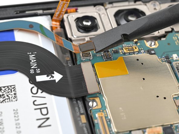
The three rear cameras are like a stack of pancakes, so remove them one by one from top to bottom. You got this!
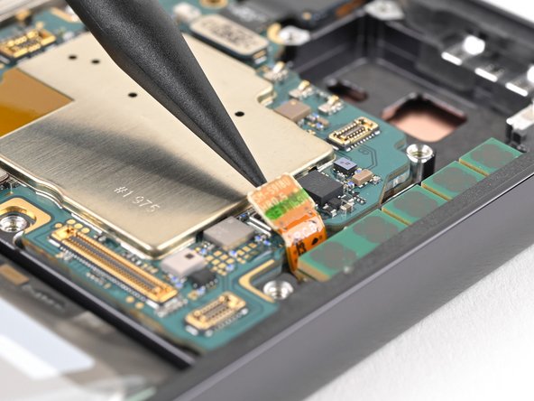
– Flip the motherboard over, like a pancake! It’s showtime for the rear camera press connectors!
– Now, grab your spudger and gently pry up the ultrawide camera press connector. Think of it like giving it a little high-five.
Tools Used
Step 33


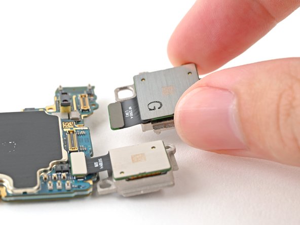
– The ultrawide camera is attached to the motherboard and the main camera with some metal pegs.
– Hold onto the motherboard, and gently lift the ultrawide camera out of its peg holes. You’re almost there!
Step 34
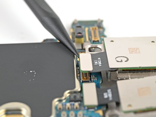

– Let’s get that camera out! Use the pointy end of a spudger to carefully lift up and disconnect the camera connector. It’s like giving it a little high five, but with a tool.
– Now, gently lift the camera off the motherboard. It’s like saying goodbye to your old friend, but don’t worry, it’s just going for a little adventure. If you’re feeling a bit lost, you can always schedule a repair.
Tools Used
Step 35

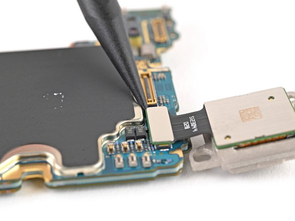

– Let’s get that telephoto camera out! Use the tip of a spudger to gently lift and disconnect the camera’s connector.
– Now, carefully lift the telephoto camera off the motherboard and give it a little wave goodbye.
– When putting everything back together, remember to install the rear cameras in reverse order (Telephoto → Main → Ultrawide) so they all fit snugly. You got this!
Tools Used
Step 36

– All three of those snazzy rear cameras are staying right where they are!