Samsung Galaxy S24 Plus Motherboard Replacement
Duration: 45 minutes
Steps: 36 Steps
Ready to swap out that motherboard on your Samsung Galaxy S24+? This guide walks you through each step to get your device back in action. Take your time, stay organized, and remember—if things get tricky, you can always schedule a repair. Let's get started and bring your phone back to life with a little patience and some good vibes.
Step 1


Let your battery dip under 25 %—a sleepy battery is safer than a fully juiced one. If it’s looking puffy like a marshmallow, treat it with extra TLC and proper safety moves.
- Disconnect any cables from your phone to start fresh.
- Press and hold the side button along with the volume down button, then tap 'Power off' to switch off your device.
Step 2

A hair dryer, heat gun, or hot plate can work for this step—just go easy on the heat! Too much can mess with your display or battery, so keep things warm, not toasty.
- Warm up your iOpener and chill it on the right edge of the back cover for about two minutes. Let that heat do its magic!
Tools Used


Step 3

Struggling to make a gap? Try heating things up a bit more to loosen that stubborn adhesive. Keep an eye on the iOpener instructions so you don’t end up with a superheated device.
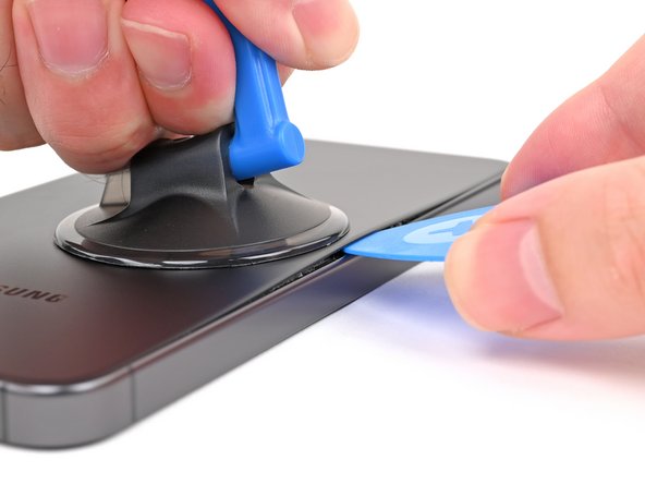
- Stick a suction cup onto the back cover, aiming for the spot closest to the middle of the right edge. Keep it pretty centered for the best grip.
- Grab that suction handle and gently pull upward with steady, firm pressure—think of it as a gentle tug to loosen things up and create a little space between the cover and the frame.
- Slide an opening pick into the gap you just made. Easy does it—this is the start of your access point for the next step!
Tools Used

Step 4


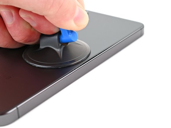
- Sweep the pick along the right edge, slicing through that sticky adhesive like a boss.
- Keep the pick parked near the bottom right corner—don’t let that adhesive sneak back together!
Step 5

- Warm up an iOpener and gently apply it to the bottom edge of the back cover for about two minutes. This will help loosen things up so you can get in there and do your thing!
Tools Used
Step 6


- Swing that opening pick around the bottom right corner to loosen up the sticky stuff holding things together.
Step 7

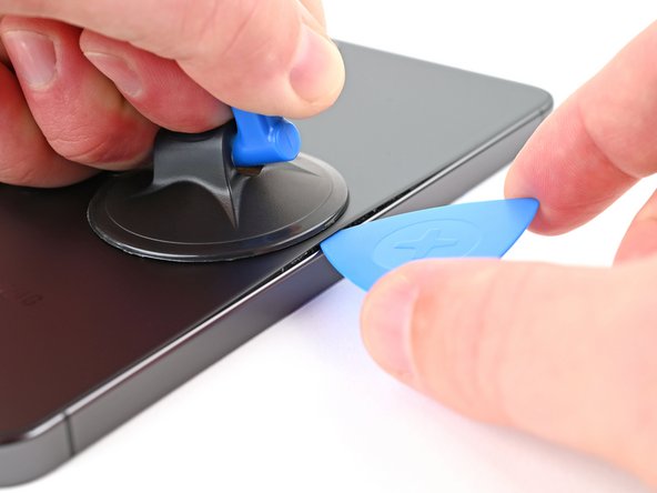
- Pop in another pick at the bottom-right corner—your adhesive is on notice.
- Skate that pick along the bottom edge to the left corner, slicing the sticky stuff like a pro.
- Park the pick in the bottom-left corner so the glue doesn’t sneak back together while you work.
Step 8

- Warm up a heated iOpener and gently press it against the left edge of the back cover for a cozy two minutes.
Tools Used
Step 9


- Gently rotate the opening pick around the bottom left corner to loosen the adhesive and get things started.
Step 10


- Pop in a third opening pick at the bottom left corner.
- Gently slide that pick up toward the top left corner to break the adhesive's hold.
- Keep that pick nestled near the top left corner so the adhesive doesn't get any funny ideas about sticking back together.
Step 11

- Gently press a heated iOpener onto the top edge of the back cover and hold it there for about two minutes. This helps loosen things up so you can lift it off more easily.
Tools Used
Step 12


- Swing that opening pick up and around the top-left corner like you're tracing a rainbow—gentle pressure pops the adhesive loose and keeps the good vibes rolling.
Step 13


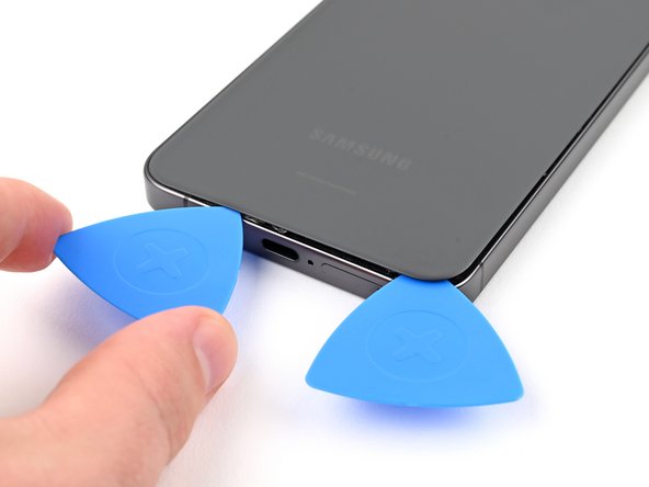
- Pop in that fourth opening pick right up in the top left corner.
- Slide your pick over to the top right, breaking up any clingy adhesive along the way.
- Let the pick chill near the top right so the adhesive doesn’t reunite. Onward to the next step!
Step 14


Check out that sticky square around the rear mic—it's lounging just above the flash.
- Line up the tip of your opening pick with the flash to get started.
- Gently slide the pick underneath the top edge of the back cover, feeling it catch on the adhesive as you go.
- Keep pushing the pick downward toward the bottom of the device, while softly lifting the cover until it separates from the adhesive holding it in place.
Step 15


If the back cover isn’t budging, grab an opening pick to slice through any stubborn adhesive that might’ve cozied back up to your device.
Now’s a smart time to power up and make sure everything is working before you close things up. Just don’t forget to fully shut down your phone before you dive back in.
Getting water resistance back depends on how lovingly you reapply the back cover adhesive—but heads up, your device’s official IP rating won’t make a comeback after this.
- Pop off that back cover—it’s easier than finding WiFi at a campsite.
- When you’re putting everything back together:
- Say goodbye to all leftover adhesive on the back cover and phone. Tweezers or fingers work, but if it’s extra stubborn, try a little heat or some isopropyl alcohol (90%+). Coffee filters or lint-free cloths are your best friends here.
- Got custom-cut adhesives? Just follow this guide and stick with it.
Tools Used


Step 16

Check out the printed arrow on the board next to each press connector—it’s your VIP pass to the best spot for prying these connectors loose.
- Grab your trusty spudger and gently pop up the wireless charging coil connector from the motherboard. Treat it like a stubborn sticker—firm but not forceful.
- When it’s time to reconnect, line up the connector with its socket, and press down with your fingertip—side to side—until you feel that satisfying click. If it’s not clicking, double-check the alignment and try again. No need to wrestle with it!
Tools Used

Step 17


- Grab your Phillips screwdriver and remove the thirteen 3.5 mm screws holding down the wireless charging coil and the loudspeaker. First, take out the six screws securing the wireless charging coil, then unscrew the seven screws keeping the loudspeaker in place. If you need a hand during the process, you can always schedule a repair.
Step 18


- Grab your trusty spudger and slide it into the notch at the top left corner of the loudspeaker—look for the arrow pointing the way.
- Gently pry up to pop the loudspeaker free from the frame. It’s a bit like opening a stubborn cookie jar, but with way less mess.
Tools Used
Step 19


- Gently lift the loudspeaker away from the frame using your fingers. You've got this!
- Carefully take out the wireless charging coil and loudspeaker from the frame. Easy peasy!
- When putting everything back together, give the edges of the loudspeaker a little press to snap it back into place before you reinsert those screws. You're almost there!
Step 20

- Grab your trusty spudger and gently pry up to disconnect that battery press connector. You've got this!
Tools Used
Step 21


- Grab your trusty spudger and gently pop up both interconnect cable connectors from the daughterboard. No need to wrestle—just a little finesse and they'll come right off!
Tools Used
Step 22


- Grab your spudger and gently pop up both interconnect cable press connectors from the motherboard. Easy does it—no need to wrestle with them!
Tools Used
Step 23


- Gently disconnect and remove the interconnect cables from the phone, making sure not to force anything. If you need a hand with the process, you can always schedule a repair.
Step 24


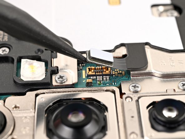
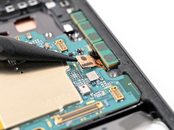
- Grab your trusty spudger and gently pop up the earpiece speaker press connector. Easy does it—no need for brute force!
Tools Used
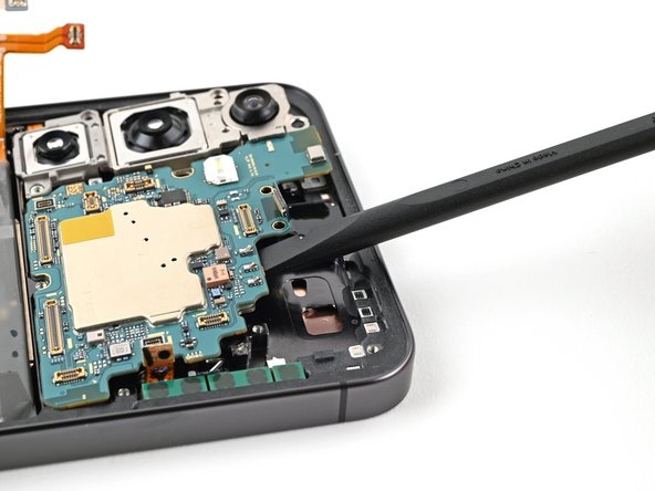
Step 25


- Grab your trusty Phillips screwdriver and get ready to tackle those five 3.5 mm-long screws holding the earpiece speaker in place. Let's get this party started!
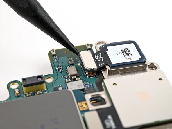
Step 26

- Let's get started! Carefully insert the flat end of a spudger between the bottom edge of the earpiece speaker and the metal plate on the motherboard. This is where the magic happens!
- Now it's time to set the earpiece speaker free! Twist the spudger to unclip it from the frame, and gently remove it. You're doing great!
- When it's time to put everything back together, remember to insert the top edge of the earpiece speaker into the frame first. Then, press down and clip it back in. You're almost done! If you need help, you can always schedule a repair
Tools Used
Step 27

Keep that spudger in its happy place! Avoid poking it anywhere else to steer clear of any accidental damage to those delicate surface-mounted components.
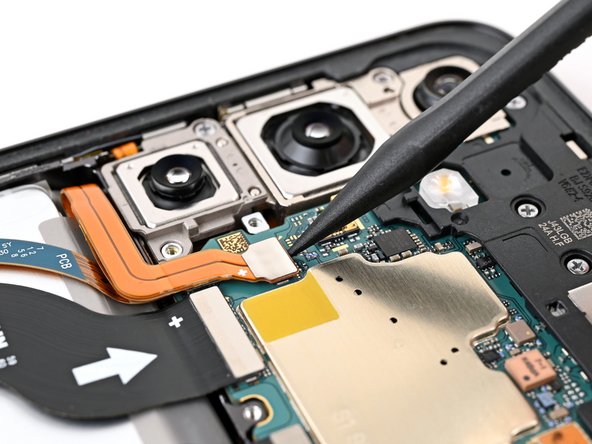
- Gently slide the tip of your spudger under the top left corner of the upper antenna press connector. A little nudge goes a long way!
- Carefully lift and disconnect the upper antenna press connector from the motherboard. It’s a simple step, but take your time!
Tools Used
Step 28

Be careful where you place that spudger! Stick to the designated spots to keep those delicate surface-mounted components safe and sound.
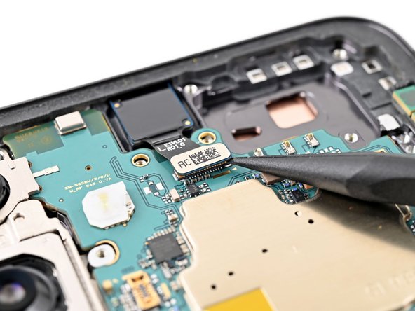
- Take your trusty spudger and slide the tip underneath the bottom right edge of the front camera connector. Nice and easy!
- Gently pop the front camera connector up and away from the motherboard—disconnecting it like a pro.
Tools Used
Step 29
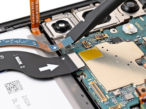
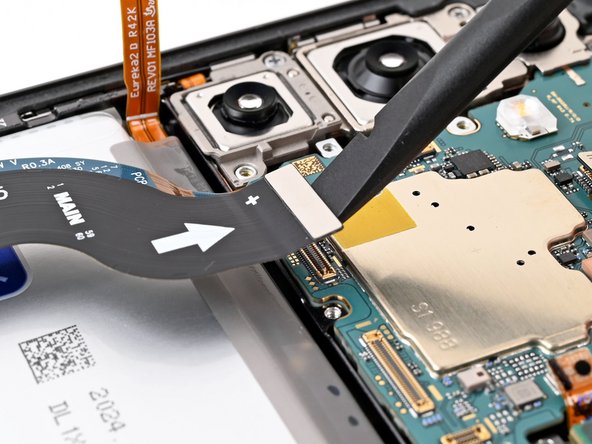

- Grab your trusty spudger and gently pop up the display and lower antenna cable connectors from the motherboard. Take it slow and steady—no need for heroics!
Tools Used
Step 30

- Grab your Phillips screwdriver and spin out the two 3.5 mm screws—give 'em a little twist and the motherboard will thank you.
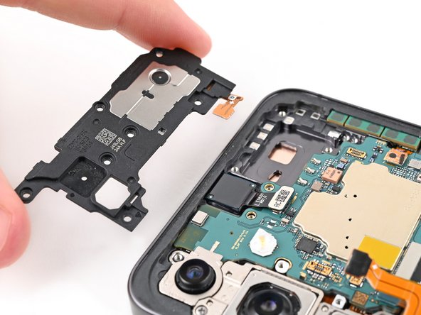
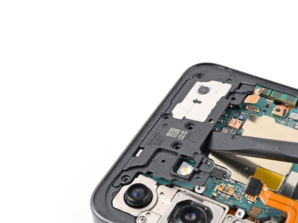
Step 31
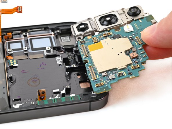

- Slip the flat end of your spudger between the top edge of the motherboard and the phone frame, right where the earpiece speaker sits.
- Gently pry up against the frame to pop the motherboard out of its spot—lift it out and set it aside.
- When putting everything back together, double-check that all the cables are clear before dropping the motherboard back into place.
Tools Used
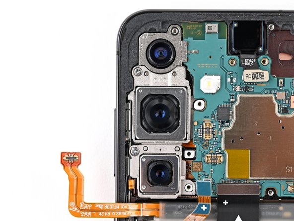
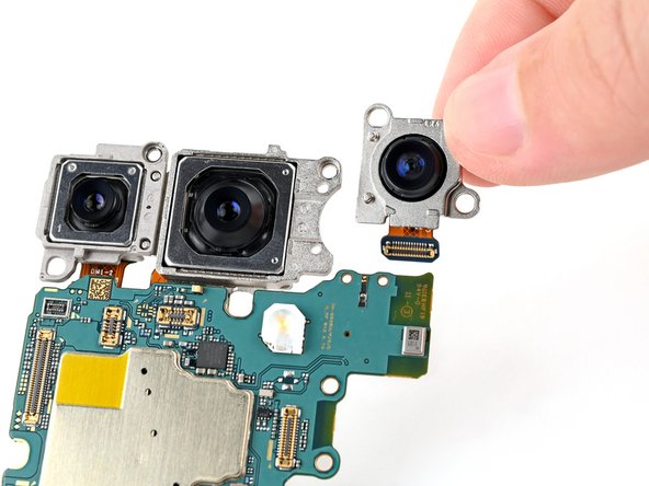
Step 32

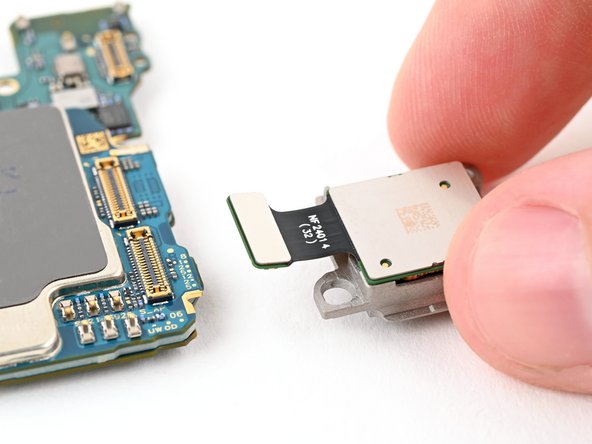
The three rear cameras are stacked like a totem pole and should be removed in this order: ultrawide, then main, and finally telephoto. The ultrawide camera sits at the top when installed, so it's the first to come out.
- Flip the motherboard over to reveal the back of the camera connectors. Then, grab a spudger and gently pry up to disconnect the ultrawide camera's press connector. If you need a hand with this, you can always schedule a repair.
Tools Used
Step 33

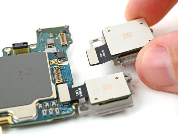
The ultrawide camera is attached to the motherboard using two sturdy metal pegs—think of them as little boots keeping your camera firmly in place.
- Gently slide the pegs of the ultrawide camera out of their cozy spots in the motherboard to remove it. Take your time, no rush here!
Step 34

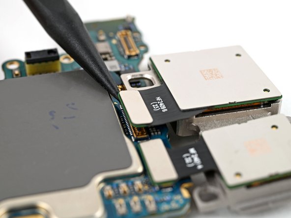
The primary camera is located right in the center.
- Slide a spudger under the camera’s press connector, give it a gentle nudge upward, and let the connector pop free like it’s waving goodbye.
- Peel the camera off the motherboard—lift, smile, and set it aside like you just won a tiny tech trophy.
Tools Used
Step 35
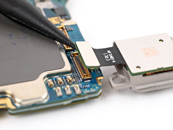

The telephoto camera sits at the bottom when installed—think of it as the camera's ground level buddy, ready for those zoomed-in shots.
- Grab your trusty spudger and gently pop up the telephoto camera’s connector.
- Lift the telephoto camera straight off the motherboard and set it aside.
- When putting things back together, make sure to install the rear cameras in this order for a perfect fit:
- Start with the telephoto (that's the small one with the metal back).
- Next up, the main camera (big, also rocking a metal back).
- Finish with the ultrawide (the one with the plastic back).
Tools Used
Step 36

- To get your device back in action, just reverse these steps - easy peasy!
- Hit a snag? Don't worry, some basic troubleshooting or a chat with our community at Salvation Repair can get you back on track.
- Remember to responsibly recycle your e-waste with an R2 or e-Stewards certified recycler.
- You did it! If you need help with anything else, you can always schedule a repair with Salvation Repair.