Samsung Galaxy S24 Ultra Screen and Battery Assembly Replacement
Duration: 45 minutes
Steps: 49 Steps
Heads up—this guide is all about swapping out your screen and battery together. Ready for some DIY action?
Ready to give your Samsung Galaxy S24 Ultra a fresh start? This guide walks you through swapping out the screen and battery assembly—the whole combo: screen, battery, and frame, all in one piece. Double-check you’ve got the right part before you dive in! If you just need a new battery, check out the dedicated battery guide. Same goes for the screen—there’s a separate guide for that, too.
Step 1


Run that battery down to under 25% before you start—fully juiced lithium-ion packs can be drama queens. Spot a puffy battery? Chill and use extra care, no heroics needed.
- Disconnect all cables from your phone to start clean. Then, press and hold the side button along with the volume down button, and when the options appear, tap 'Power off' to shut down your device. If you need a hand, just schedule a repair.
Step 2

If you have a hair dryer, heat gun, or hot plate on hand, feel free to use them, but keep an eye on the temperature! You don't want to accidentally cook your phone—especially the display and internal battery, which are pretty sensitive to heat. Just a little warmth is all you need!
- Warm up an iOpener and gently press it against the right edge of the back cover for about two minutes. Keep it there until the adhesive softens enough to loosen.
Tools Used


Step 3
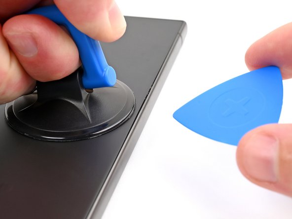

If you're having a tough time creating a gap, give it a bit more heat to loosen the adhesive further. Just follow the iOpener instructions carefully to prevent overheating. If you need a hand, you can always schedule a repair.
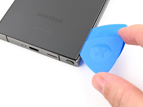
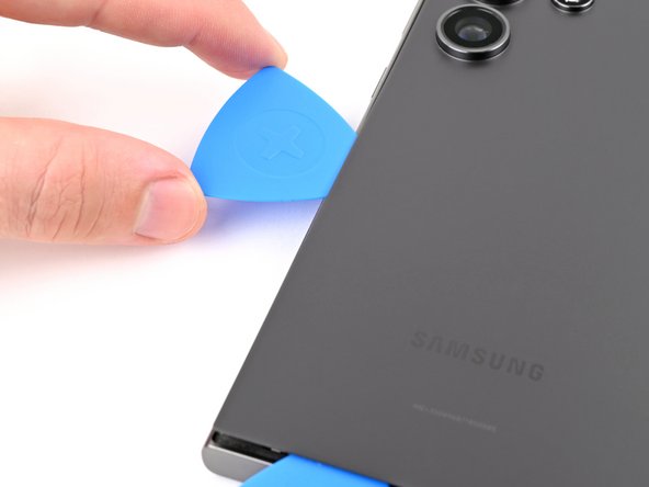
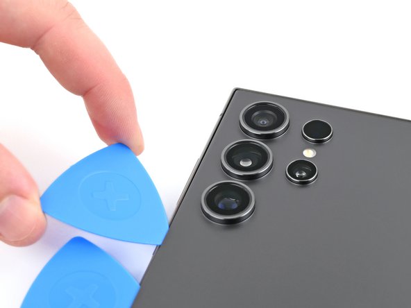
- Stick a suction cup near the middle of the right edge on the back cover. Give it a solid, steady tug to loosen the cover from the frame, creating a small gap. Slide an opening pick into that gap to start prying it open gently. If you need a hand, you can always schedule a repair.
Tools Used

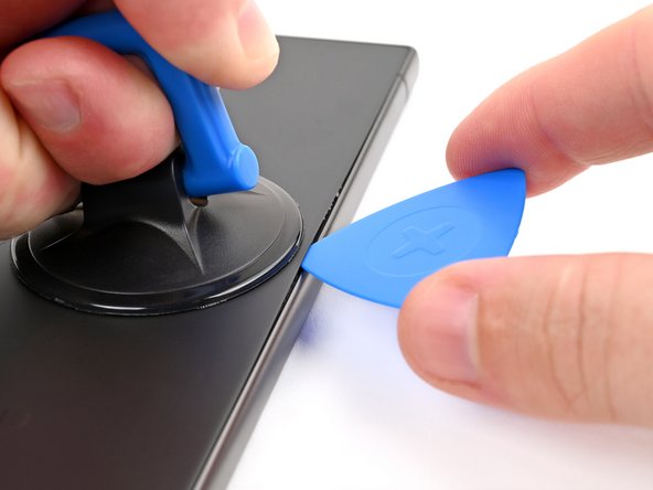
Step 4


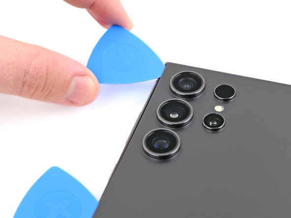
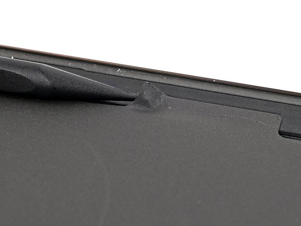
- Gently slide your pick along the right edge to loosen the adhesive—think of it as giving it a little nudge to start the party. Keep the pick in place near the bottom right corner to stop the adhesive from sealing back up on you. If you get stuck or need a hand, you can always schedule a repair.
Step 5

- Warm up the bottom edge of the back cover with a heated iOpener for about two minutes. This gentle heat helps loosen the adhesive and makes the cover easier to remove. If you need help, you can always schedule a repair.
Tools Used
Step 6
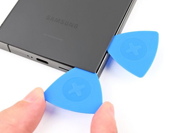

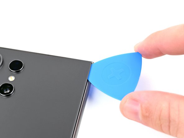
- Slide a second opening pick in next to the first one, down near the bottom of the right side. You’re building yourself a little toolkit of picks—nice!
- Twist the pick around the bottom right corner like you're scooping ice cream. This will help break up the sticky stuff holding things together.
Step 7

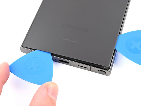
- Glide the opening pick along the bottom edge to break up that stubborn adhesive.
- Leave the pick chilling in the bottom left corner so the adhesive doesn’t sneak back together.
Step 8

- Warm up the left edge of the back cover with a heated iOpener for about two minutes. Give it a little spa treatment—it’ll make the next steps way easier!
Tools Used
Step 9

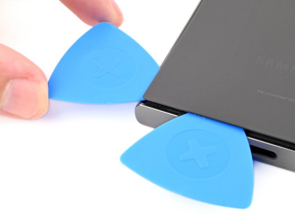
- Slide a third opening pick in next to the second one, close to the left side of the bottom edge.
- Gently rotate the opening pick around the bottom left corner to break free the adhesive.
Step 10

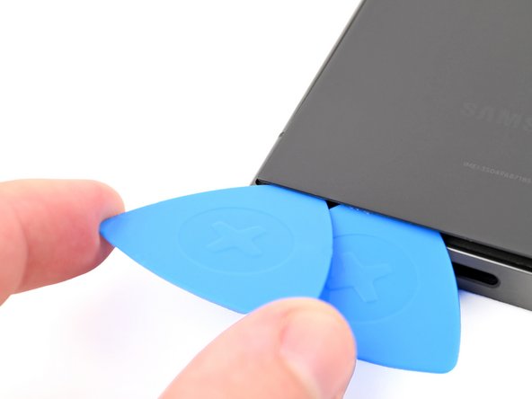
Keep that pick under 4 mm, or you might just give the antenna cable a little too much love!
- Glide your opening pick along the left edge to break up that sticky adhesive, but don’t go all the way to the power button just yet.
- Keep the pick hanging out near the power button—this stops the adhesive from playing matchmaker and sealing things up again.
Step 11

- Heat things up by applying a heated iOpener to the top edge of the back cover for about two minutes. This will help loosen things up and make the repair process smoother.
Tools Used
Step 12

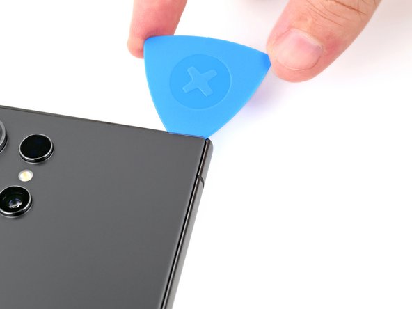
- Slip an opening pick into the gap at the top right edge. Then, gently pivot the pick around that corner to loosen the adhesive and start separating the parts.
Step 13

Keep that pick shallow—don't go deeper than 4 mm up top, or you might accidentally poke the sensor or camera!
- Gently glide the pick along the top edge to break free that pesky adhesive.
Step 14

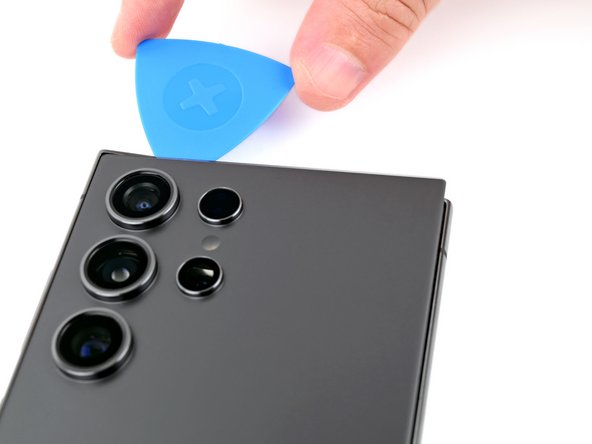
Keep that pick shallow—no deeper than 4 mm—or your camera might catch a case of the blues!
- Now it's time to get that pick sliding! Carefully work it around the top left corner and down the left edge. This will help loosen the remaining adhesive, making it easier to separate the parts.
Step 15


If your cover is still clinging to the frame, grab an opening pick and gently run it around the edges—any sneaky adhesive should let go.
Now’s a great time to fire up your phone and make sure everything’s working. Test all the functions you can think of. Just remember to shut it down again before you keep tinkering.
- Pop off the back cover with confidence.
- When putting things back together:
- Clear out any leftover sticky bits with tweezers or your fingers. If the adhesive’s being stubborn, a little heat goes a long way.
- Rolling with custom-cut adhesives? Check out our guide for smooth sailing.
- Using double-sided tape instead? We’ve got a guide for that, too.
Tools Used

Step 16
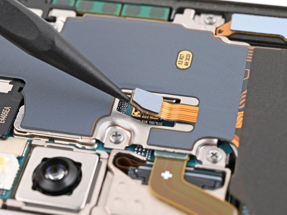

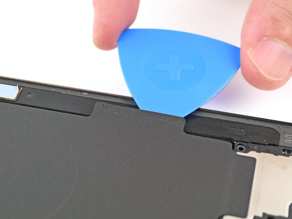
You'll notice a small arrow printed on the board near each press connector—think of it as the repair GPS. Stick to prying at that spot to keep those delicate surface-mounted components happy and intact. Prying elsewhere might turn into a game of 'what not to break,' so follow the arrow like it's your repair secret handshake.
- Grab your trusty spudger and gently pry up to disconnect the wireless charging coil press connector from the motherboard. Easy peasy!
- When it's time to reconnect those press connectors, just line them up with their socket and give a gentle press with your fingertip—first on one side, then the other—until you hear that satisfying click! No need to force it; if it’s being stubborn, just reposition and give it another go. You've got this!
Tools Used

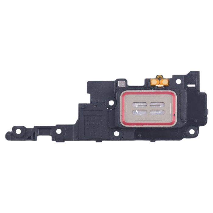
Step 17
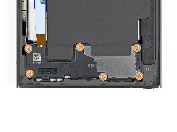

- Grab your trusty Phillips screwdriver and unscrew the ten 3.5mm-long screws holding in the wireless charging coil and loudspeaker.
- Four screws are keeping the wireless charging coil in place.
- Six screws are locking down the loudspeaker.
Step 18

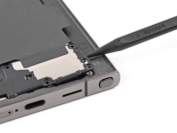
- Gently lift a corner of the wireless charging coil's tab using a spudger—it's glued to the right edge of the frame, so take your time and be careful. If you need a hand, you can always schedule a repair.
Tools Used
Step 19

- Grab a trusty opening pick and gently wedge it between the tab and the frame. Work your way around to loosen things up—think of it as giving your device a friendly nudge to get things moving. If you find yourself in a pinch, remember, you can always schedule a repair for extra help.
Step 20

Check out the engraved arrow on the loudspeaker—it’s pointing you right to the best spot for prying. Handy, right?
- Slip the tip of your spudger into the gap between the right side of the loudspeaker and the frame. Go on, give it a gentle nudge.
- Lift up to pop the loudspeaker loose from the frame. It might put up a little resistance, but you’ve got this!
Tools Used
Step 21
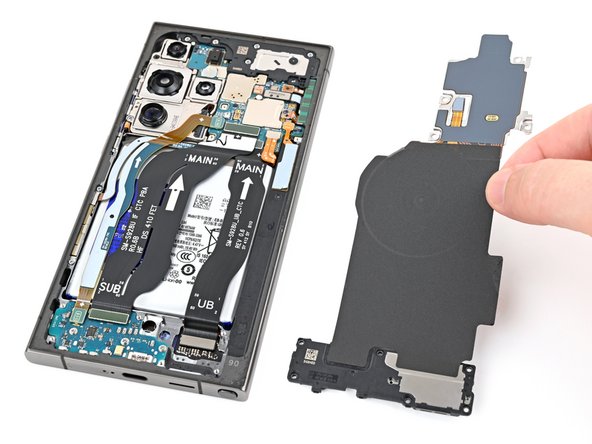

- Carefully take out the wireless charging coil and loudspeaker from the frame. Think of it as a little tech treasure hunt!
- When you're putting everything back together, give the edges of the loudspeaker a gentle press to clip it snugly to the frame before you pop those screws back in. You've got this!
Step 22


- Let's get started! Use a spudger to carefully pry up and disconnect the battery press connector. Remember to take your time and be gentle to avoid any damage.
Tools Used
Step 23

- Grab a spudger and gently pry up to disconnect both interconnect cable press connectors from the motherboard. Keep it steady and careful—no rush needed. If you need a hand, you can always schedule a repair.
Tools Used
Step 24

- Grab your trusty spudger and gently pop up both interconnect cable connectors from the daughterboard. Easy does it—no need to rush!
Tools Used
Step 25
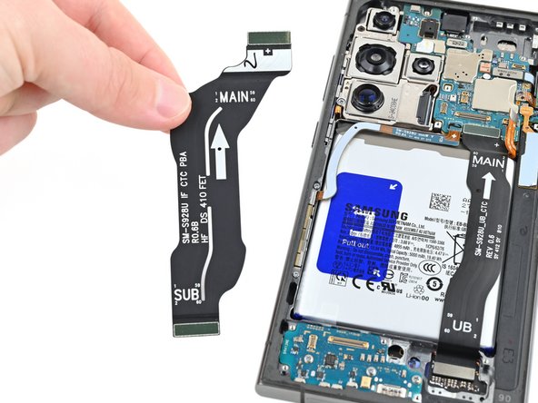

- Unplug those interconnect cables and set them aside—your phone’s feeling lighter already!
Step 26

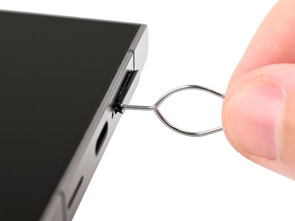
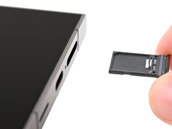
Oops! If you accidentally poked the microphone hole with the SIM eject tool, no worries—chances are you didn’t do any damage to the mic. Just a little accidental adventure, nothing to stress about. If you need a hand with anything else, remember you can always schedule a repair.
- Grab a SIM eject tool, a paperclip straightened out, or a tiny bit of wire—whatever gets the job done—and poke it into the hole on the bottom edge of your phone where the SIM tray lives. Push gently but firmly until the tray pops out. Carefully pull out the SIM card tray, and you're all set to move forward. If you hit any snags, you can always schedule a repair.
Step 27

- Grab your Phillips screwdriver and unscrew those three 3.5 mm-long screws holding down the daughterboard. Easy does it—you're making progress! If you need help, you can always schedule a repair.
Step 28
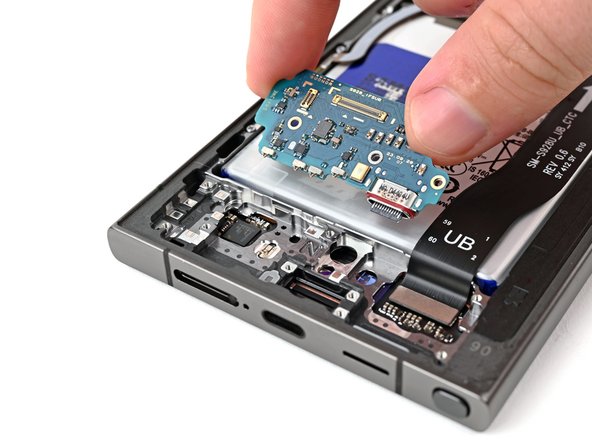

Avoid prying against the battery directly. Instead, angle your spudger to gently pry against the frame—think of it as giving the battery a friendly nudge without poking the bear.
- With the tip of your spudger, pop up the top left corner of the daughterboard—think of it as giving your device a gentle nudge.
- Lift out the daughterboard and set it aside like the VIP it is.
- When putting things back together, slide the USB-C port into its spot at an angle first, then press the daughterboard down so it sits flat on the frame.
Tools Used
Step 29

- Grab your trusty spudger and gently pop up the earpiece speaker connector—easy does it!
Tools Used
Step 30

- Grab your trusty Phillips screwdriver and let's unscrew those five 3.5 mm-long screws holding the earpiece speaker in place. You've got this!
Step 31


- Start by sliding the pointy side of your spudger under the bottom of the earpiece speaker, right beneath that little engraved arrow.
- Gently pry upwards with the spudger to release the speaker and carefully lift it out.
- When putting everything back together, make sure to line up the top of the earpiece speaker first with the frame before snapping it back into place.
Tools Used
Step 32

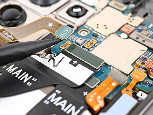
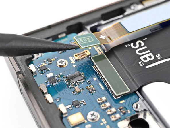
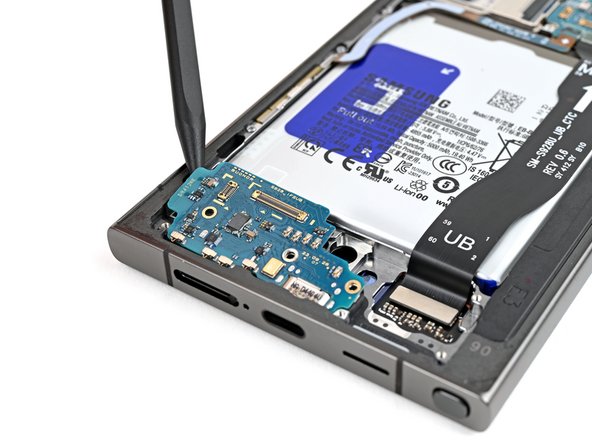
- Grab a spudger and gently pry up the display cable press connector from the motherboard. Take your time—patience is key to a smooth disconnect. If you need a hand, you can always schedule a repair.
Tools Used
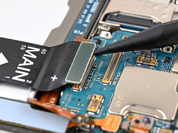
Step 33

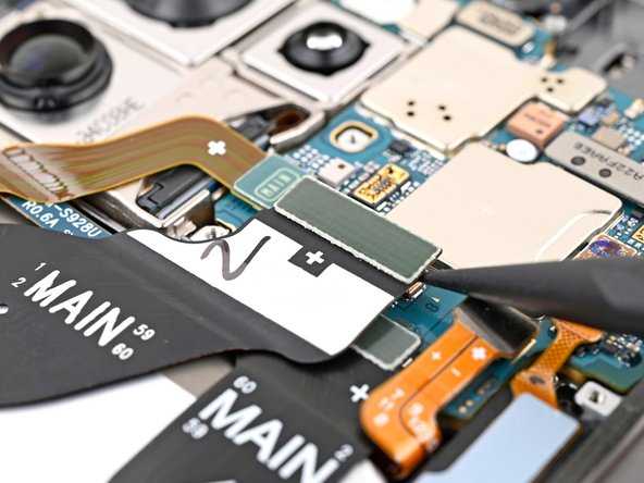
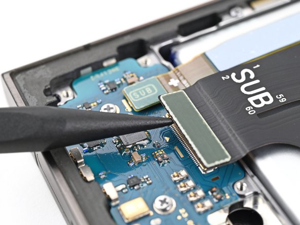
- Pop the spudger under the display cable connector like a tiny crowbar and gently tease it free from the daughterboard—think of it as unplugging your phone from a really snug outlet.
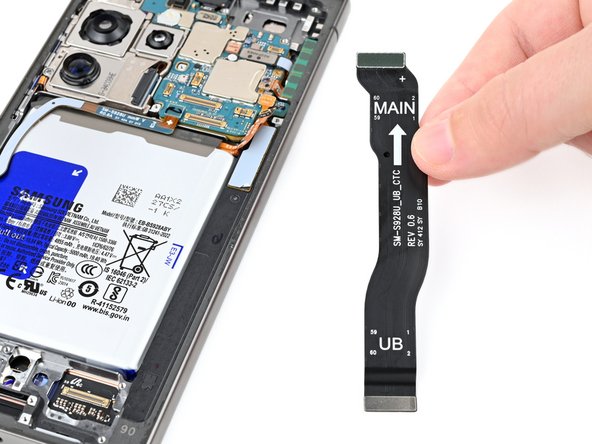
- Lift the display cable out and wave goodbye to the old screen.
Tools Used
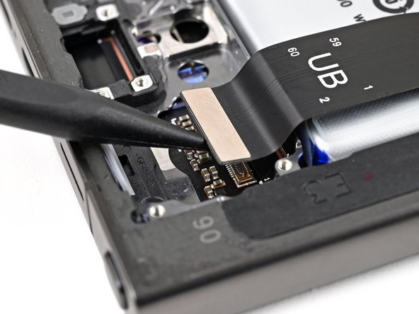
Step 34

- Grab your spudger and gently lift the lower antenna press connector off the motherboard. Easy does it!
Tools Used
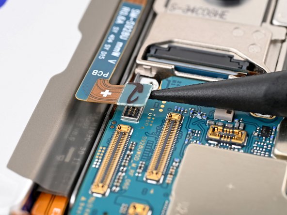
Step 35

- Let's get that stylus port press connector disconnected from the motherboard! Use a trusty spudger to carefully pry it up and set it free.
Tools Used
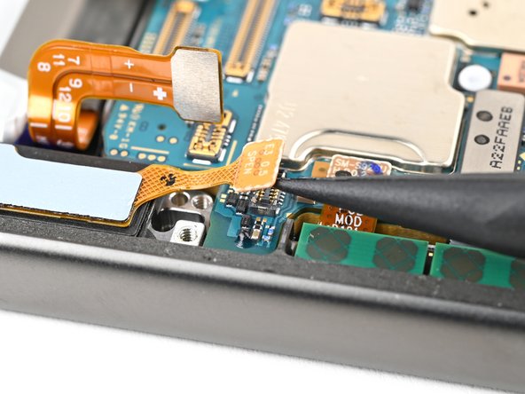
Step 36

- Grab your trusty spudger and gently pop up the upper antenna press connector from the motherboard. Nice and easy does it!
Tools Used
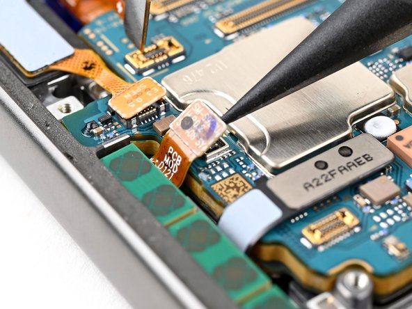
Step 37


- Let's get started! Use a spudger to carefully pry up and disconnect the fingerprint scanner press connector from the motherboard.
Tools Used
Step 38


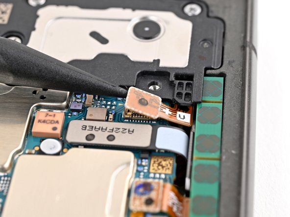
- Grab your trusty spudger and gently pop up the front camera’s press connector from the motherboard. No heavy lifting required!
Tools Used
Step 39

- Grab your trusty Phillips screwdriver and let’s get those screws out! First up, we need to tackle the two screws holding down the motherboard:
- Remove the 4.0 mm-long screw sitting to the left of the top camera.
- Next, take out the 3.5 mm-long screw located to the left of the bottom camera.
Step 40

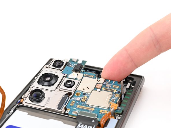
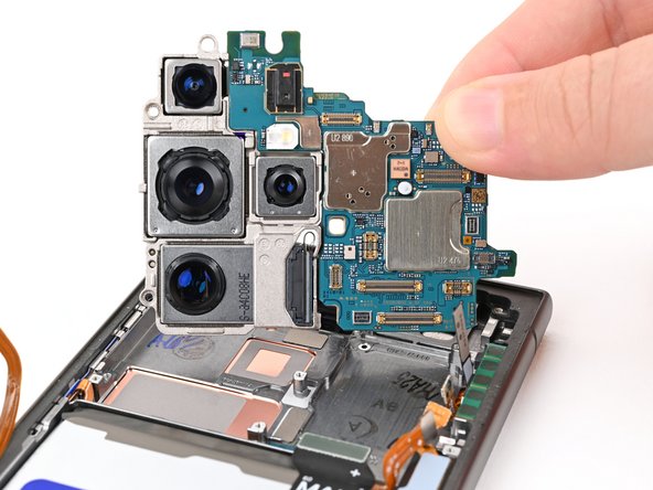
Watch out for any loose cables—keep them from getting caught or tangled up as you work. Stay safe and keep those cords clear!
- Gently lift the top of the motherboard using your finger or a spudger. No need to get fancy—just a little nudge will do.
- Go ahead and remove the motherboard. Take a deep breath; you’re doing great.
- When you’re putting everything back together, make sure all those press connectors are on top of the motherboard before sliding it back in. Trust me, your future self will thank you!
Tools Used
Step 41
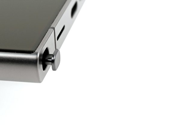

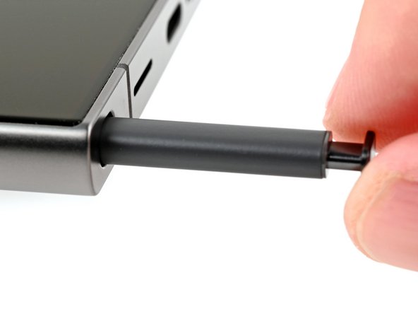
The stylus pops out just a bit—like it's trying to say hello. This is a normal sign that it's ready for a gentle upgrade or a quick check. No worries, it's all part of keeping your device in top shape. If you need a hand with anything, remember you can always schedule a repair.
- Press the button at the bottom of the stylus to eject it, then gently pull the stylus out. If you need a hand, you can always schedule a repair.
Step 42

- Grab your Phillips driver and unscrew those two 2.5 mm-long screws holding down the lower antenna. Easy does it!
Step 43

- Time to get a grip on that antenna bracket. Insert one arm of your trusty angled tweezers or a SIM eject tool into the bottom screw hole on the lower antenna bracket - it's like a little doorway to freedom for your bracket.
- Pry up and lift the antenna bracket out of its cozy little recess. Keep going until you can get a good grip on it with your fingers. You got this!
Tools Used

Step 44

- Time to get started! Carefully lift and remove the lower antenna to move forward with your repair.
Step 45

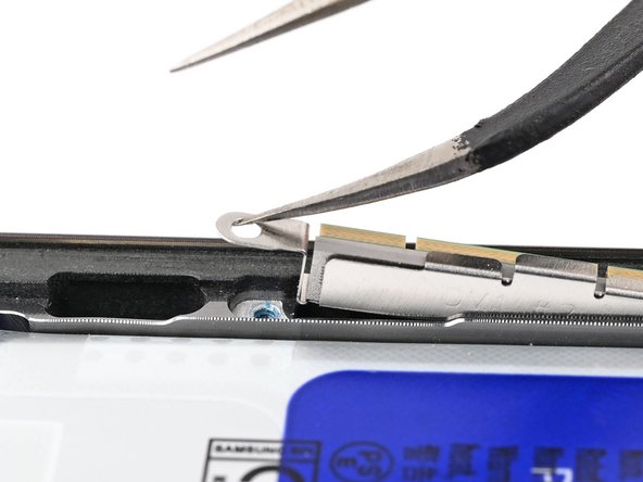
- Let's get that antenna cable out! Carefully insert the flat end of a spudger under the upper antenna cable, right between the antenna and the frame. Easy does it!
- Now, gently twist the spudger to loosen the antenna from its adhesive. It's like a little dance move - twist and lift, and you're free!
Tools Used
Step 46

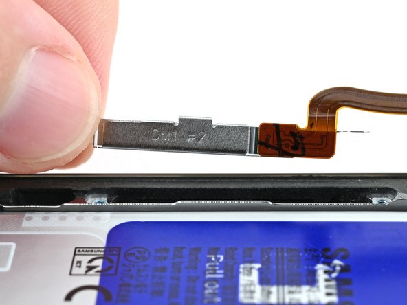
- Gently lift off the upper antenna and set it aside.
Step 47

You can also grab a hair dryer, heat gun, or hot plate for some extra warmth, but watch out! Too much heat can be a bummer for your phone's display and battery. Keep it cool and steady, and you'll be just fine!
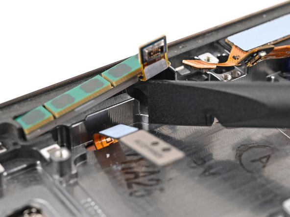
- Flip the device so the screen faces up. Warm up an iOpener and gently press it against the top edge of the screen for about two minutes to help loosen the front camera adhesive. Then, flip the device back over so you have access to the back of the front camera. If you need a hand with this process, you can always schedule a repair.
Tools Used
Step 48
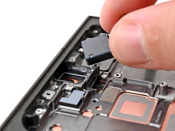
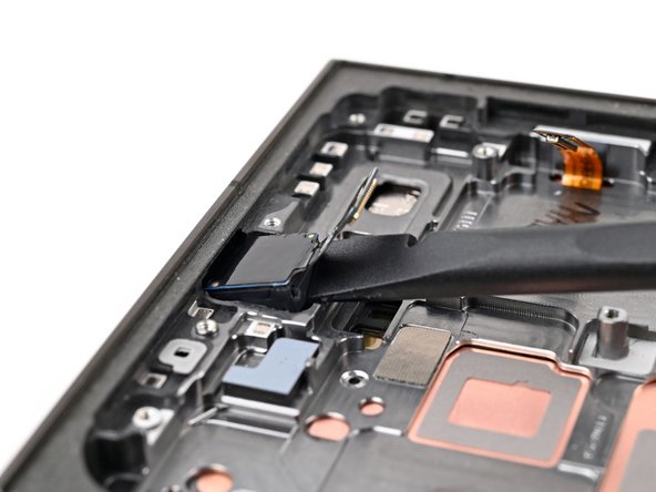

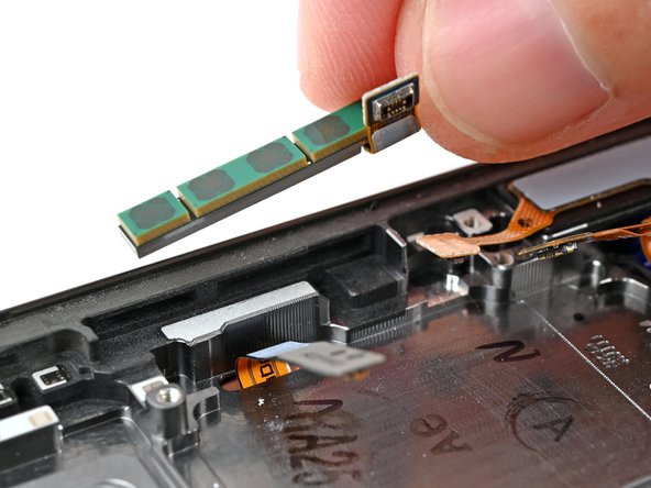
The adhesive holding the camera is pretty stubborn. Take your time, and if the front camera feels stuck, a little extra heat should do the trick. Just be careful not to separate the sensor from the lens—like this.
If the camera is feeling a bit stubborn, grab a SIM eject tool and gently scrape away the epoxy that's holding it in place. You've got this!
- Time to set that front camera free! Use the flat end of a spudger to carefully pry it out of its cozy spot in the frame.
- Gently lift and remove the front camera - you're making great progress!
Tools Used
Step 49

- Time to flip the script—pop everything back together in reverse order and give your gadget a high-five.
- If the repair vibe still feels off, run through some quick troubleshooting or hit up our community for backup.
- Send that old part on a green vacation—drop e-waste at an R2 or e-Stewards recycler.
- Need a hand? You can always schedule a repair.