Samsung Galaxy S25 Edge Sub Board Replacement
Duration: 45 minutes
Steps: 27 Steps
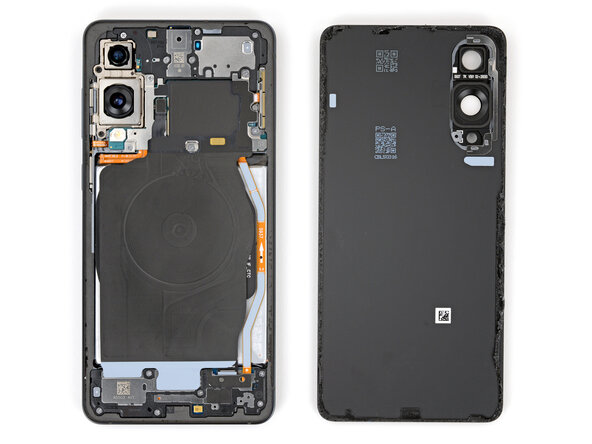
Get ready to dive into this guide for swapping out the sub board (also known as the SIM board or daughterboard) in your Samsung Galaxy S25 Edge! If your device is playing hard to get with the SIM card or if the SIM card tray is being a bit stubborn, it might just be time for a sub board upgrade. A quick tip: while you could leave the USB‑C port and interconnect cables in place (just disconnect them from the sub board), taking them out can help you avoid any mishaps while you're at it. Don't forget, you'll need some fresh back cover adhesive to wrap up this repair nicely. If you need help, you can always schedule a repair!
Step 1
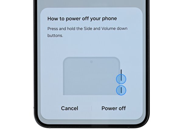
Make sure your phone’s battery is under 25% before diving in. A charged lithium-ion battery can get pretty heated—literally—and might catch fire if it gets damaged by accident.
- First things first, let's give your phone a little break. Power it down completely and unplug any cables hanging around.
Step 2
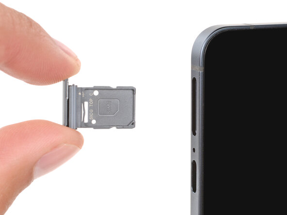
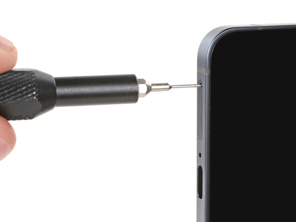
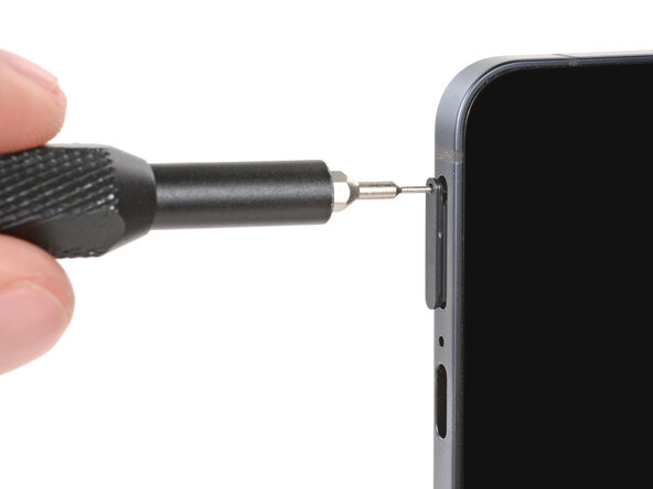
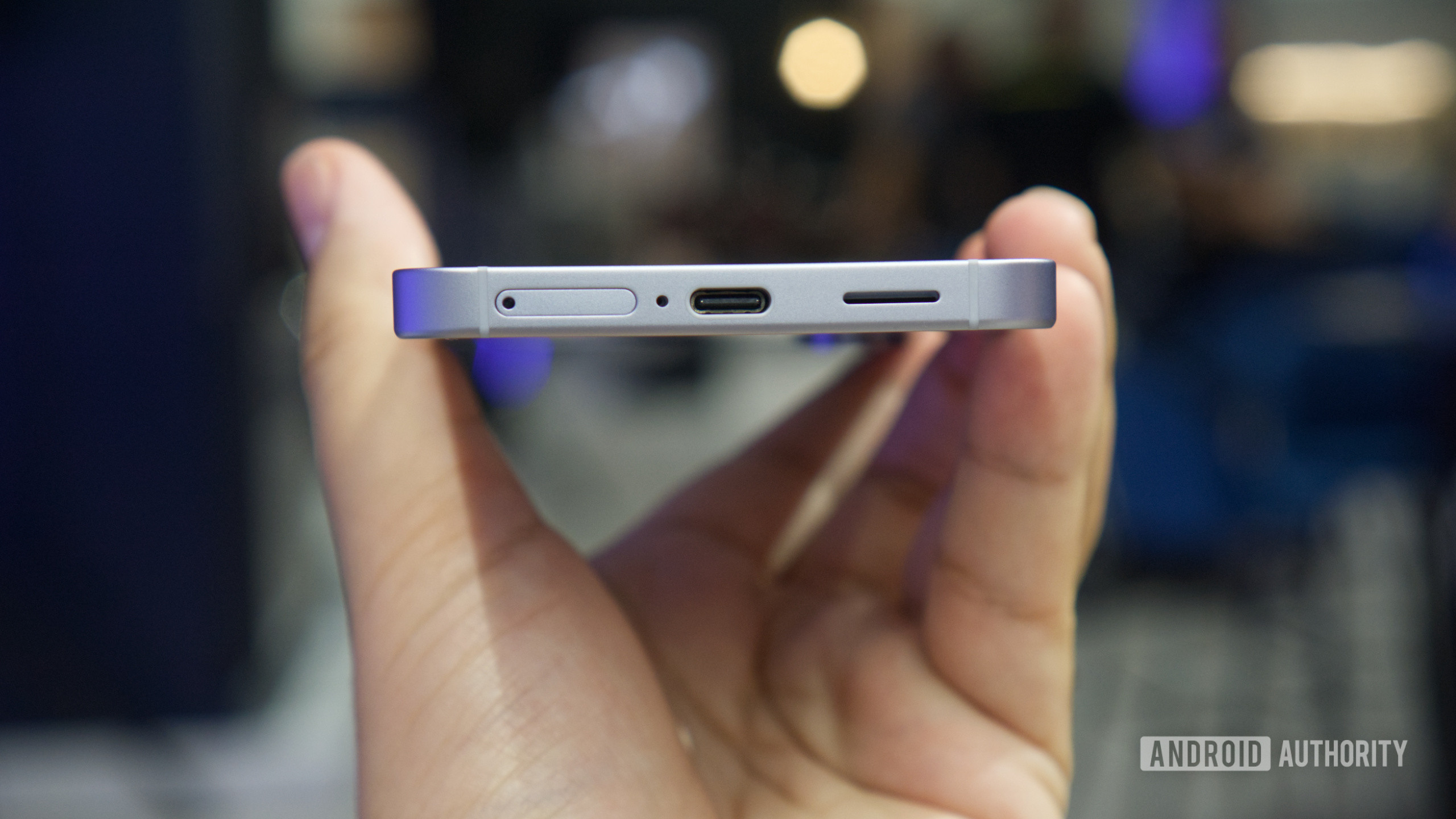
Watch out for the tiny mic hole next to the SIM tray—don’t mix them up!
- Grab a SIM eject tool, the right SIM bit, or even a trusty straightened paperclip and aim for the little hole next to your phone’s SIM card tray on the bottom edge.
- Give it a confident push—don’t be shy!—to pop out the SIM tray.
- Slide the SIM tray completely out of your phone.
- When it’s time to put the tray back in, just make sure the hole lines up on the left, then push it in until it fits snugly.
Step 3
The back cover is held on with some mild adhesive. Warm it up a bit to loosen things up and make the cover easier to remove.
A hair dryer, heat gun, or hot plate will all do the trick for heating the cover.
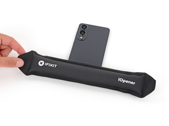
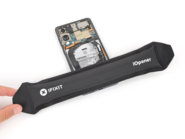
- Warm up your iOpener and place it gently on the bottom edge of the back cover for two minutes. This will help soften that stubborn adhesive!
Tools Used


Step 4
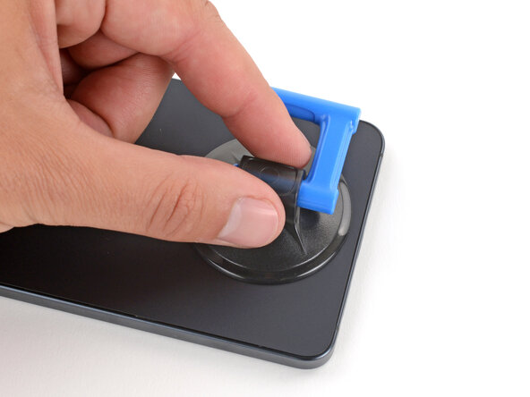
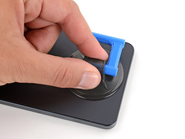
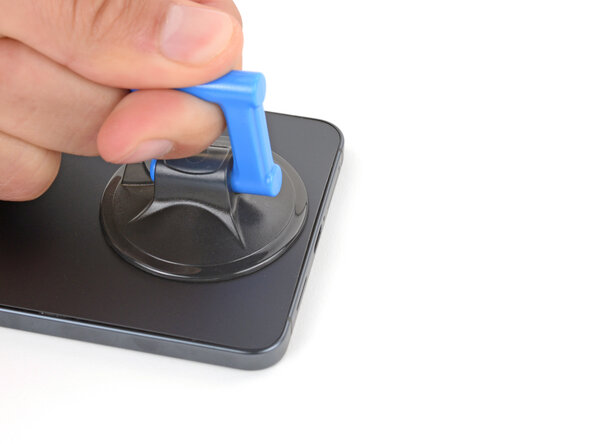
- Grab a suction handle and place it right in the middle of the bottom edge of the back cover. Make sure to get as close to the edge as you can!
Tools Used

Step 5
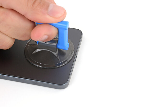
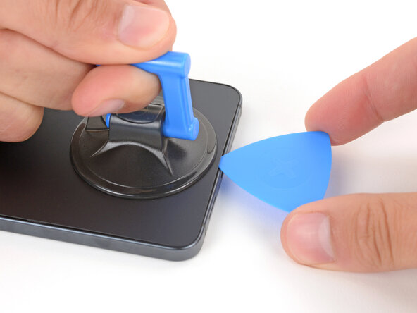
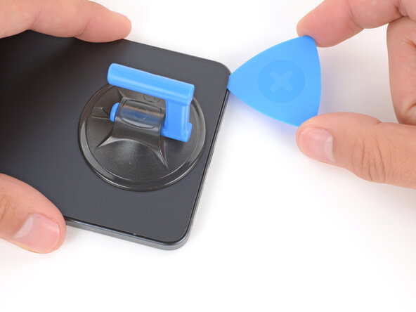
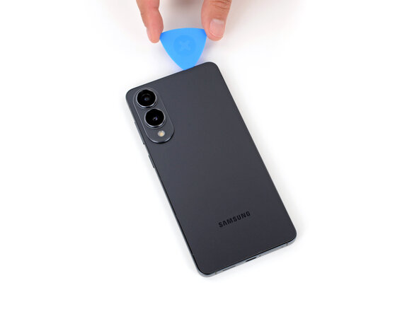
- Give that suction handle a strong, steady pull until you see a little gap between the cover and the frame. You're doing great!
- Now, slide the tip of your opening pick right into that gap. You've got this!
Tools Used
Step 6
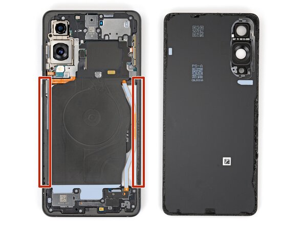
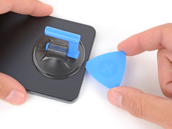
As you peel apart the left and right edge adhesive, remember to keep your pick under 3 mm deep—this way, you'll steer clear of the wireless charging coil and interconnect cable. You've got this!
- The back cover is held in place with adhesive all along the edge of the frame. Use this photo to help guide you as you work your way around and gently separate the sticky stuff.
Step 7
If you're having a tough time peeling away that adhesive, no worries! Just turn up the heat a bit more and give it another shot. You've got this!
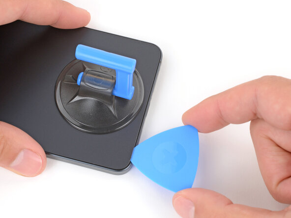
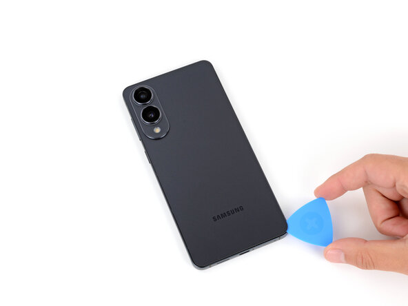
- Gently glide your opening pick along the bottom edge to break free the adhesive holding the back cover in place. Keep it smooth and steady, and you'll be in the zone in no time!
Step 8
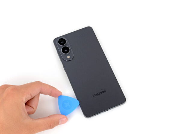
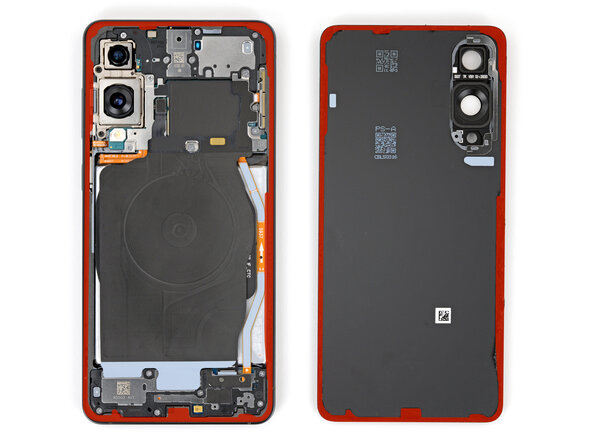
Hey there! Just a quick heads up: be sure not to slide your pick too far under those long left and right edges. Keep it safe and sound!
- Keep gliding your pick all the way around the back cover to loosen up every last bit of adhesive.
Step 9
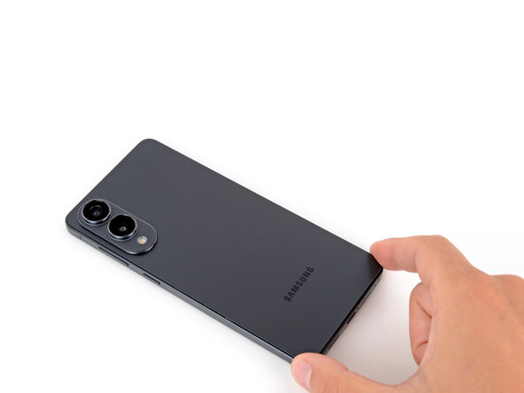
Having a bit of a struggle? No problem! Just take a peek around the edges for any leftover adhesive and give it a gentle nudge with your opening pick to help separate things. You've got this!
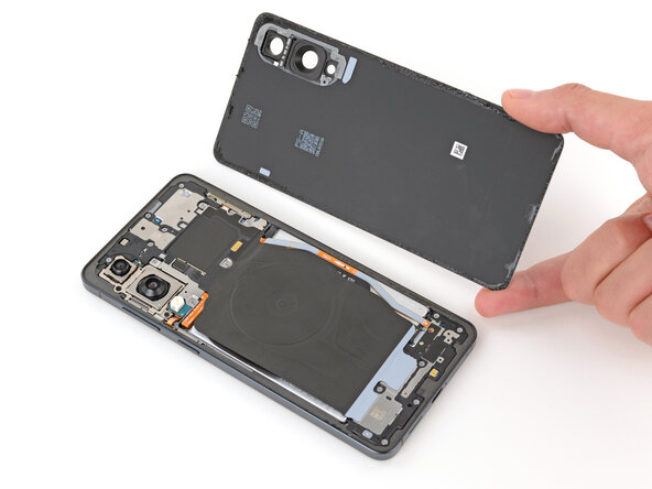
- First up, let’s pop off that back cover. It’s time for some serious inner exploration!
- Now, while you're putting everything back together:
- This is a great moment to power up your device and check if all the functions are working like a charm before you seal it up. Just remember to turn it off completely before diving back in to work on it.
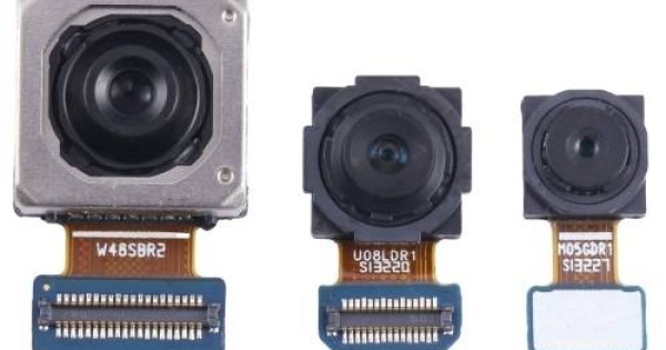
- Give your rear cameras a quick once-over for any pesky smudges. If you spot any, take a clean lint-free cloth and gently wipe them away.
- When applying your new back cover adhesive, you’ll want to figure out whether it fits better on the frame or the back cover. Check the cutouts and contours to see where it aligns perfectly. If it coincides with the back cover, follow this guide. If it lines up with the frame, you’ll want to use this guide.
Step 10
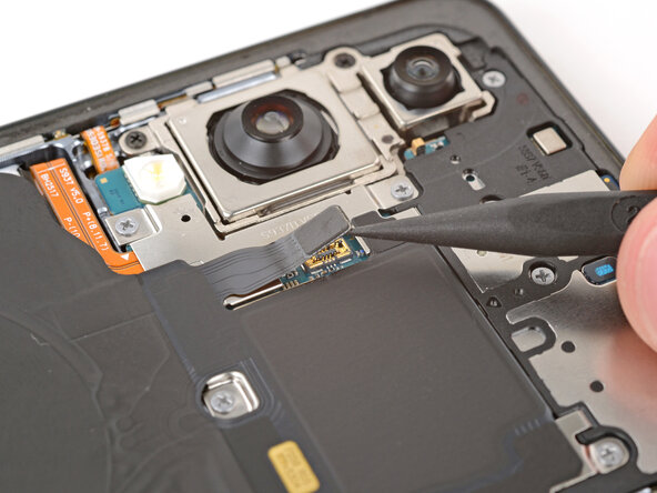
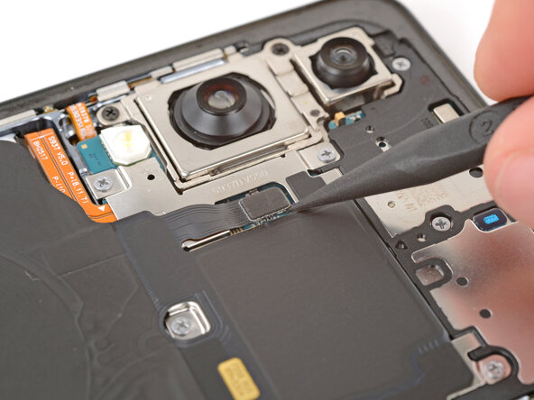
Getting the spudger under the connector can be a bit of a challenge. If it’s giving you a hard time, grab the tip of an opening pick and give that a try instead.
- Grab your spudger and gently pop up the wireless charging assembly connector from the top—easy does it!
Tools Used

Step 11
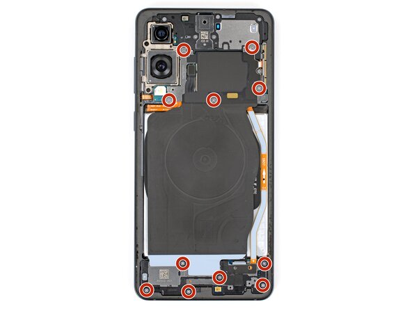
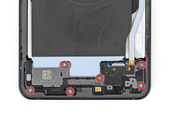
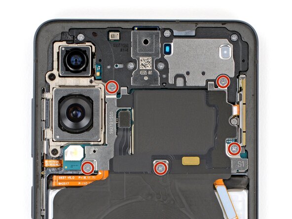
Keep tabs on each screw as you go—making sure it returns to its original spot keeps things running smoothly and avoids extra headaches down the line.
- Grab your trusty Phillips screwdriver and get ready to tackle those eleven 2.8 mm-long screws holding the wireless charging and loudspeaker assembly in place. You've got this!
Step 12
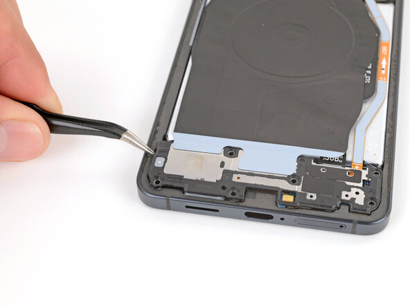
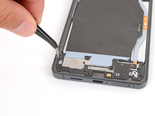
The wireless charging coil is taped to the loudspeaker with some pretty delicate stuff. For an easier time and less risk of tearing anything, lift both the coil and loudspeaker out together as one team.
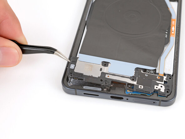
- Grab your angled tweezers and carefully lift and detach the loudspeaker from the notch on its left side. You got this!
- When putting everything back together, give the loudspeaker a good press around its edges to lock those clips in place. You're almost done!
Tools Used

Step 13
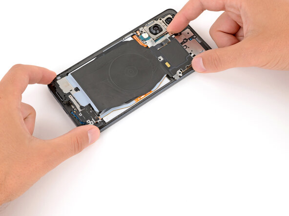
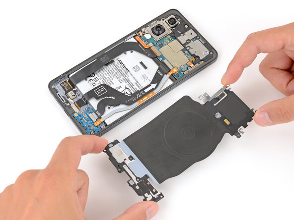
- Grab the assembly with both hands and gently lift it out to free the wireless charging and loudspeaker components. You've got this!
Step 14
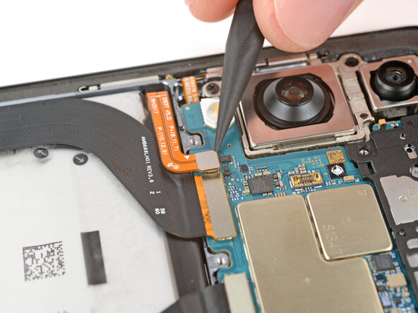
Each press connector is marked with a shiny gold arrow on the board, showing you exactly where to pry—pretty handy! Avoid prying anywhere else, since the tiny surface-mounted parts nearby are easy to damage.
- Grab your trusty spudger and gently pop up the battery connector—just a little nudge gets it free!
Tools Used
Step 15
- Grab your trusty spudger and gently nudge the point under the USB‑C port cable's press connector (it's the one labeled MAIN) to lift it off the logic board with ease!
Tools Used
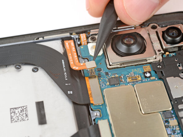
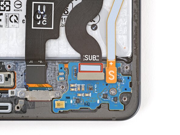
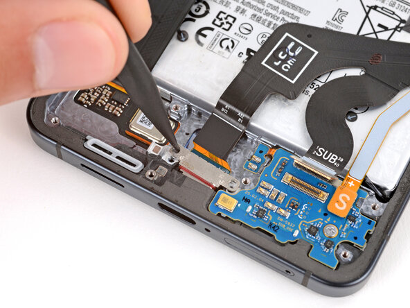
Step 16
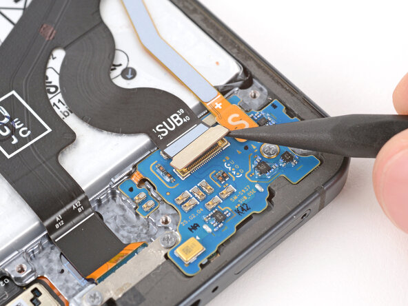
- Grab your trusty spudger and gently lift to disconnect the USB‑C port cable's press connector (look for the SUB marker) from the sub board. You've got this!
Tools Used
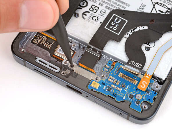
Step 17
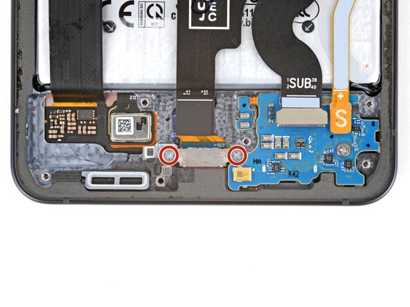
- Grab your Phillips screwdriver and gently remove the pair of 2.3 mm screws holding down the USB-C port. If you need assistance along the way, you can always schedule a repair.
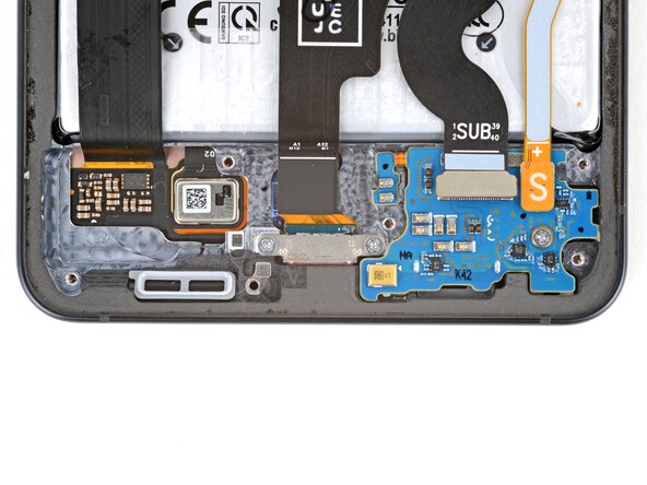
Step 18
If you're feeling a bit stuck, a hair dryer or heat gun can be your best buddy to gently warm up that cable. Just a little heat can work wonders!
- A bit of gentle heat from a heated iOpener will loosen up that mild adhesive holding the USB‑C port cable to the sub board, right below the white section under the SUB text. Let it sit for about two minutes, giving the adhesive a chance to soften up and make your life easier. If you need a hand with any step, you can always schedule a repair.
Tools Used
Step 19
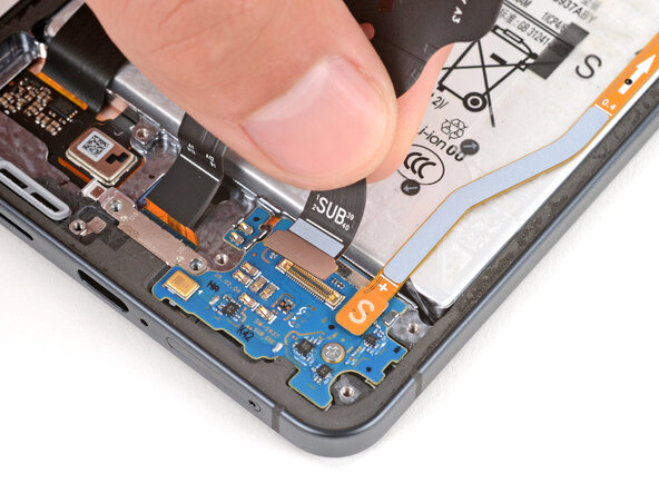
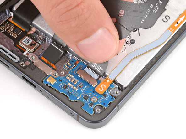
Handle the USB‑C port cable with care—no creases or tears allowed during this step!
- Gently lift the USB‑C port cable from the sub board using your fingers, like you're peeling a banana—easy does it!
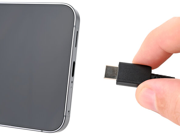
Step 20
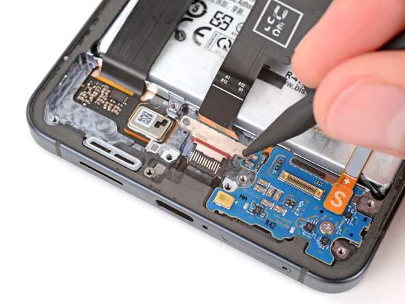
- Grab your trusty spudger and gently slide it into one of the USB‑C port screw holes, giving the port a little nudge away from the bottom edge of your phone.
- Keep alternating between the screw holes as needed until the port smoothly pops out from its cozy spot.
Tools Used
Step 21
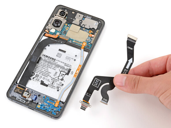
- Grab the USB-C port by its cable and lift it out.
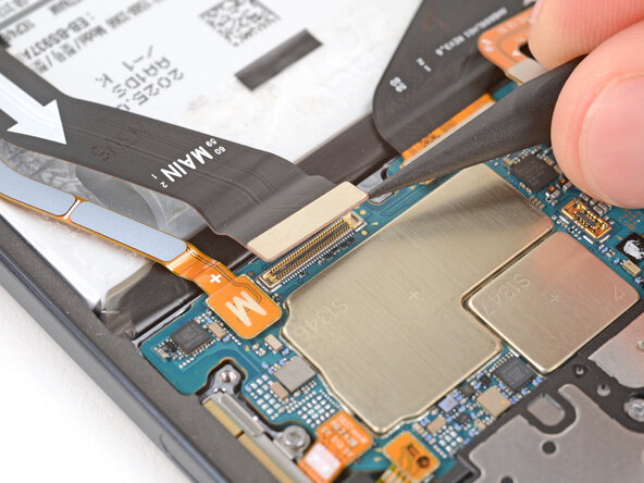
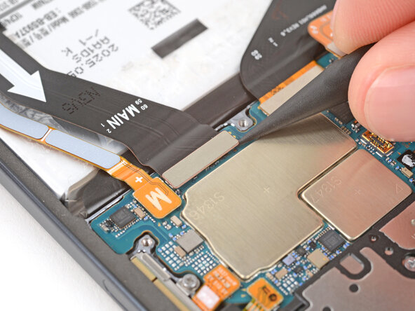
Step 22
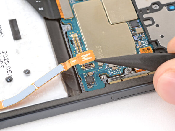
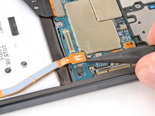
- Gently use the tip of a spudger to lift and disconnect the interconnect cable press connector (labeled M) from the logic board. You've got this!
Tools Used
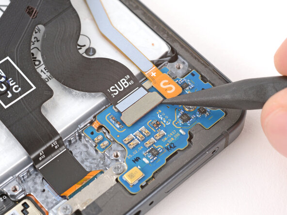
Step 23
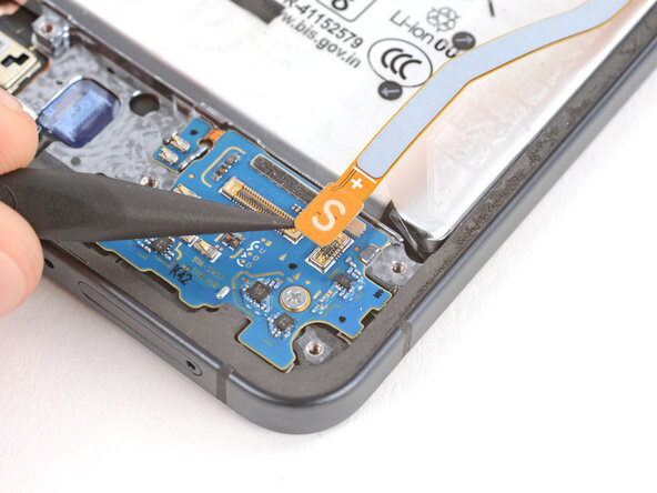
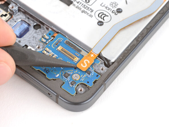
- Now it's time to carefully disconnect the interconnect cable press connector (marked S) from the sub board. Use the tip of a spudger to gently pry it up and release it.
Tools Used
Step 24
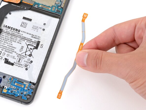
- Let's get to it! Gently disconnect the interconnect cable to keep things moving smoothly.
Step 25
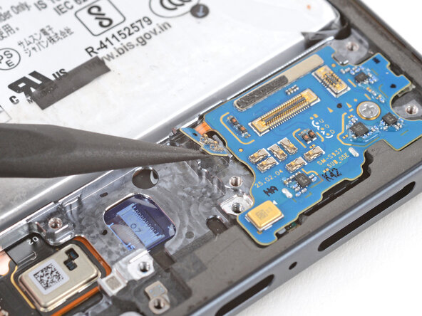
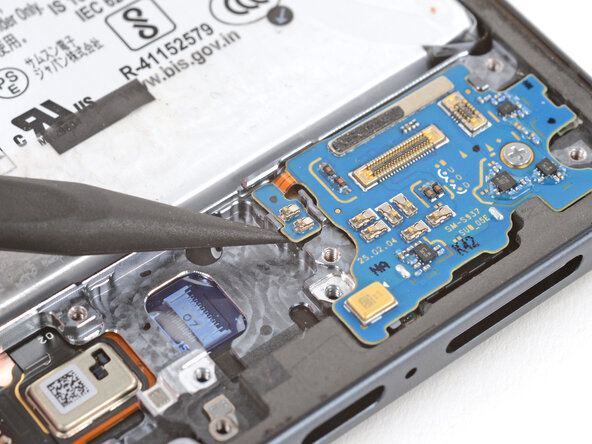
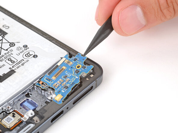
If you're running into a bit of resistance, try giving that board a gentle warm-up with an iOpener, a hair dryer, or a heat gun. If that doesn't do the trick, a drop of high-concentration (>90%) isopropyl alcohol right under the board can help melt away the adhesive. You've got this!
- Let's get started! Use the point of a spudger to carefully loosen the small extension board near the top left corner of the sub board. Take your time and be gentle, we're making progress!
Tools Used

Step 26
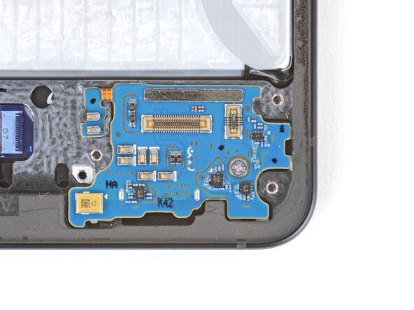
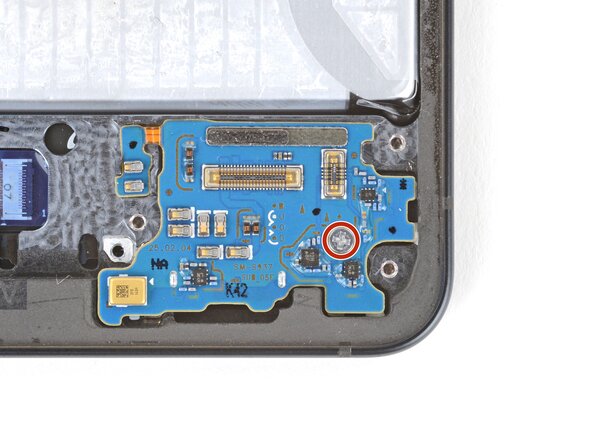
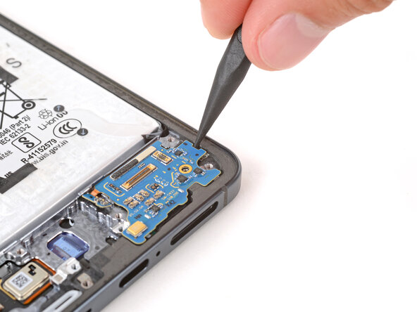
- Grab your trusty Phillips screwdriver and remove the 2.3 mm-long screw that's keeping the sub board in place. You've got this!
Step 27
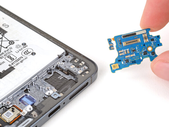
Hey there! Before you dive into prying up the sub board, don't forget to pop out that SIM card tray first. It's a small step that makes a big difference!
- Line up your new part with the original and check if you need to move any bits over or peel off any stickers before popping it in.
- To put everything back together, just follow these steps in reverse—like rewinding your favorite jam.
- Got leftover parts or busted bits? Drop them off at an R2 or e-Stewards recycler to keep things green.
- If things aren’t working out, try some basic troubleshooting or swing by our Answers Community for a hand.
- Still stuck? No stress—you can always schedule a repair and let us handle it.