Samsung Galaxy Tab A 8.0 Display Assembly Replacement
Duration: 45 minutes
Steps: 12 Steps
Get ready to tackle the replacement of your OEM Samsung Galaxy Tab A 8.0 (SM-T350) display assembly! This guide is here to help you through each step, making it simple and straightforward. Remember, if the journey gets a bit tricky, you can always schedule a repair for extra support!
Step 1

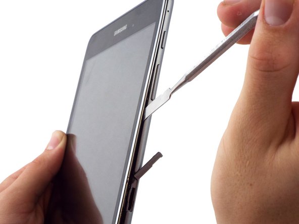
Before you dive into the disassembly party, make sure your device is taking a little nap – that means it’s turned off!
The small metal spudger is here to help you gently separate the back cover from the rest of the device, not to completely remove it.
If you can, try using a nylon spudger instead. It’s much gentler and less likely to leave any marks or scratches on your device.
– Grab your trusty small metal spudger and gently wedge it between the back cover and the device just above the memory card slot. This will help you create the separation you need to move forward.
Tools Used

Step 2

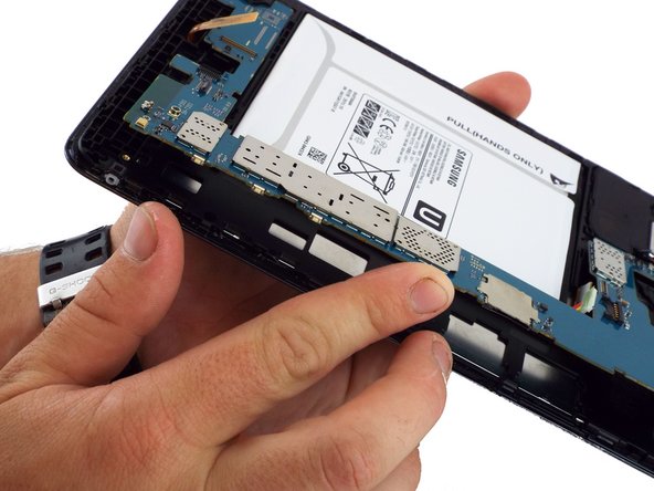
– Let’s get started by using the intermediate metal spudger to remove the back cover. Simply slide it around the edge of the device, starting from the top of the memory card slot. This will help you get inside and get to work.
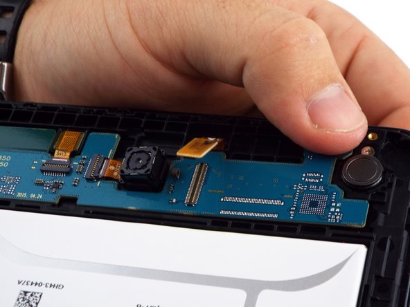
– Now that the back cover is off, take a look at the internal components. The second picture shows you what to expect – it’s like a sneak peek at the inner workings of your device!
Tools Used
Step 3

Keep those tweezers away from the motherboard! Metal tools like tweezers can leave scratches that might lead to some serious trouble.
– Gently detach the electrical connector from the motherboard with your trusty bent precision tweezers. You’ve got this!
Tools Used

Step 4


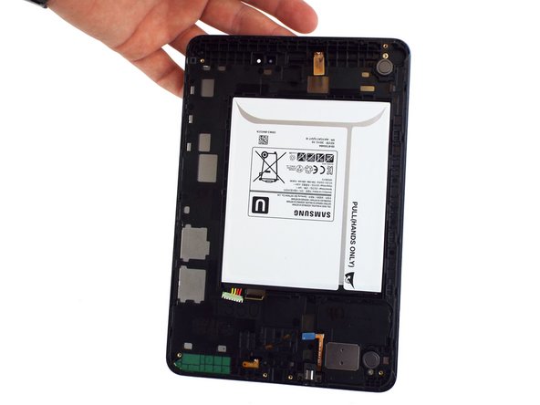
Another great way to tackle this is by gently loosening the battery with your trusty plastic spudger. Once you’re in there, just give the paper tab labeled “Pull (Hands Only)” a little tug to lift out the battery.
– Grab your plastic spudger and use the flat end to carefully separate the battery from the rest of the device. Take it slow and steady.
– Once you’ve removed the back cover and battery, your device should look like the second picture. Easy enough, right?
Tools Used
Step 5

– Grab your trusty spudger and gently nudge that press-fit display cable connector upwards to free it from the motherboard. You’ve got this!
Tools Used
Step 6

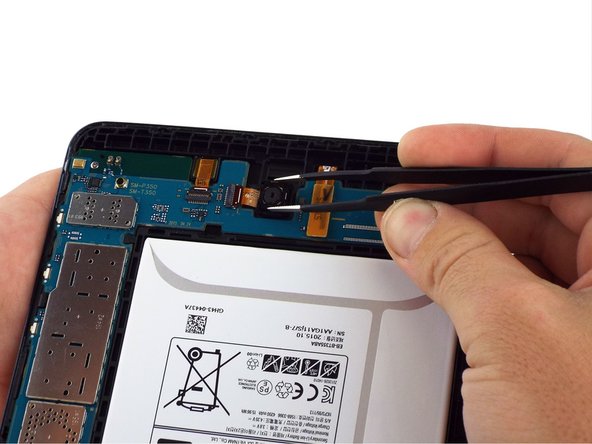
If you’re having a tough time grabbing that camera with tweezers, no worries! Just slide an opening pick between the frame and the camera, and give it a gentle lift to pop that camera out.
– Grab your spudger and gently lift the ZIF connector to release it; carefully pull out the rear-facing camera ribbon cable. It should come free without much fuss.
– Use a pair of tweezers to hold the camera gently and lift it out of the frame. Take it slow, and it’ll slide right out!

Step 8

– Gently use the flat end of a spudger to lift up and disconnect the LCD screen’s press-fit connector. It’s like a quick handshake, just a little lift and a gentle pull!
Tools Used
Step 9

– Grab your trusty spudger and use its flat end to gently lift and disconnect the 3.5mm headset jack connector. It’s a quick and easy step—just be careful and take your time!
Tools Used
Step 10

– Grab a PH000 screwdriver and twist out the two tiny 3 mm screws holding the USB port shield to the midframe. Keep those screws safe—they’re small but mighty!
Step 11
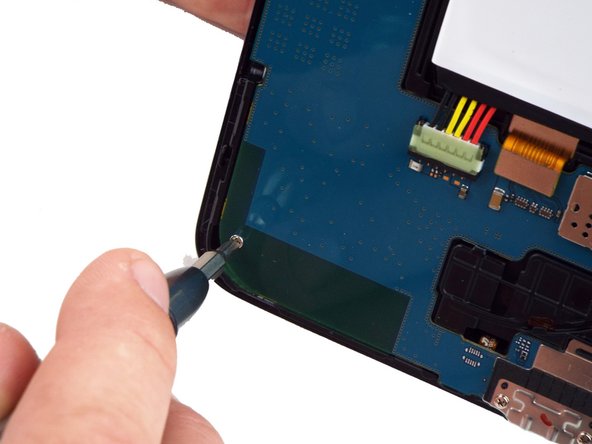

– Grab your trusty PH000 screwdriver and let’s get to work! Remove those two 3 mm screws chilling on the left side of the motherboard. You’ve got this!
Step 12

– Put everything back together by reversing these steps — easy peasy!
– If you hit a snag or it’s feeling tricky, you can always schedule a repair and let the pros take it from here.
Tools Used
Success!