Samsung Galaxy Tab S7 Plus Motherboard Replacement
Duration: 45 minutes
Steps: 36 Steps
For your safety, make sure to drain the battery below 25% before starting to disassemble your tablet. Also, watch out—there’s a good chance the delicate, unreinforced display could crack during this process. If you need help, you can always schedule a repair.
Ready to swap out the motherboard in your Samsung Galaxy Tab S7+? First, make sure your battery is below 25%—that way, if things get pokey, there’s less risk of sparks. If you notice a swollen battery, treat it with a little extra caution. The display panel is pretty delicate and loves to break if you rush, so warm things up well and take your time prying. Grab some fresh adhesive for reassembly—you’ll need it to finish the job.
Step 1

Make sure your device is completely powered down before you start. If you need help, you can always schedule a repair.
The Galaxy Tab S7+ really doesn’t want to let go of its display—the adhesive is seriously tenacious. Expect to reheat and reapply your iOpener several times before and during the removal process.
A hair dryer, heat gun, or hot plate does the trick too, just make sure not to overcook your device.
– Grab a heated iOpener and gently press it along the bottom edge of the device. This will soften the adhesive and make your next steps a whole lot easier. Remember, patience is key—take your time and enjoy the process. If you need a hand, you can always schedule a repair.
Tools Used

Step 2


Be gentle with the pick—don’t insert it more than 2 mm to keep the circuit board happy. For the display, stick to about 3 mm of insertion to avoid any damage. If you need a hand, you can always schedule a repair.
– While you’re waiting for the adhesive to loosen up, keep in mind a few things:
– There’s a long circuit board that runs parallel to the bottom edge, attached to the screen. Watch out for it!
– This image shows what it looks like when the display starts to separate from the glass panel. It’s a good visual guide.
Step 3


Hey, be gentle! Don’t insert the pick more than 2 mm to keep that circuit board happy and damage-free. If you need help, you can always schedule a repair.
If your screen is really cracked, a clever trick is to stick a layer of clear packing tape on it. This can help the suction cup grip better. If you want to get a bit creative, super strong tape can be a solid backup plan instead of using the suction handle. And if you’re in a pinch, a little superglue on the suction cup can help it stick to the screen. Remember, if you need help, you can always schedule a repair.
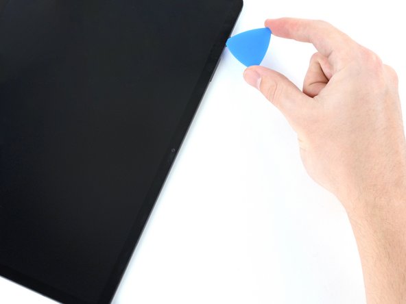
– Once the screen feels nice and toasty, stick a suction handle onto the bottom edge of the screen—get it as close to the edge as possible.
– Give the suction handle a gentle lift to crack open a small gap between the screen and the frame.
– Slide an opening pick into that gap between the frame and the screen.
– Let the pick chill in place so the sticky adhesive doesn’t sneak back together.
Tools Used

Step 4

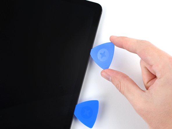

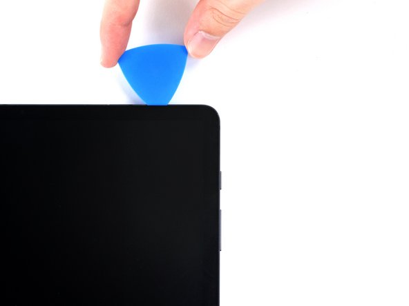
– Gently insert a new opening pick into the gap you just made, like you’re giving it a little nudge.
– Then, slide that pick along the bottom edge of the device, heading towards the bottom-right corner—think of it as guiding it on a smooth ride.
Step 5

– Warm up an iOpener and gently press it against the right edge of your device. This will help loosen the adhesive that’s holding everything together!
Tools Used
Step 6


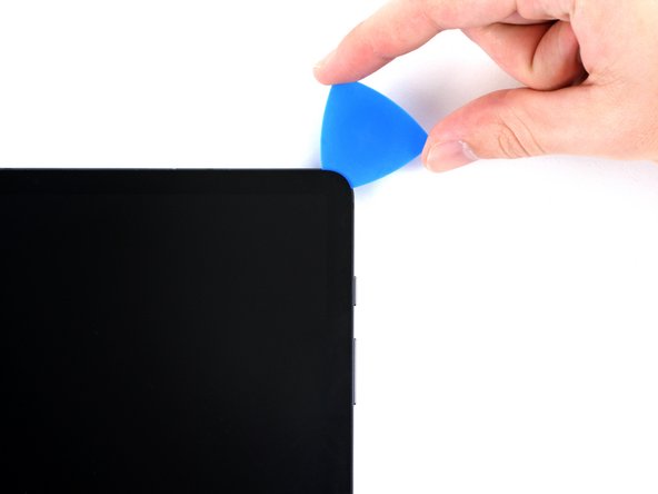
– Twist that opening pick around the bottom-right corner of your device like it’s doing a little dance.
– Keep that pick in place to ensure the adhesive doesn’t sneak back in and seal everything up!
Step 7


Keep the pick shallow—no more than 3 mm—so you don’t mess with the delicate parts hiding along the right edge.
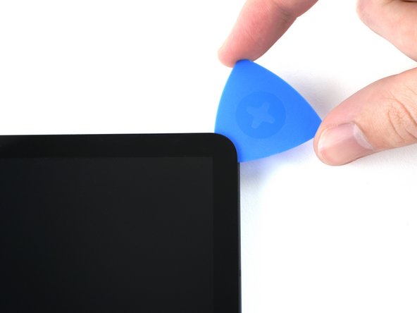
– Gently slide a fresh opening pick into the space you’ve made.
– Carefully glide that pick along the right side of your device all the way to the top-right corner.
Step 8

– Warm up your trusty iOpener and gently apply it to the top edge of your device. This will help to loosen up the adhesive hiding underneath, making your repair journey a breeze!
Tools Used
Step 9


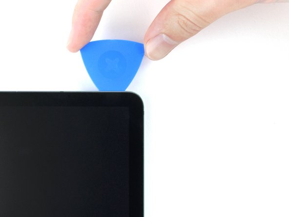
– Gently rotate the opening pick around the top-right corner of the device to loosen the adhesive.
– Keep the opening pick in place to stop the adhesive from sticking back together.
Step 10


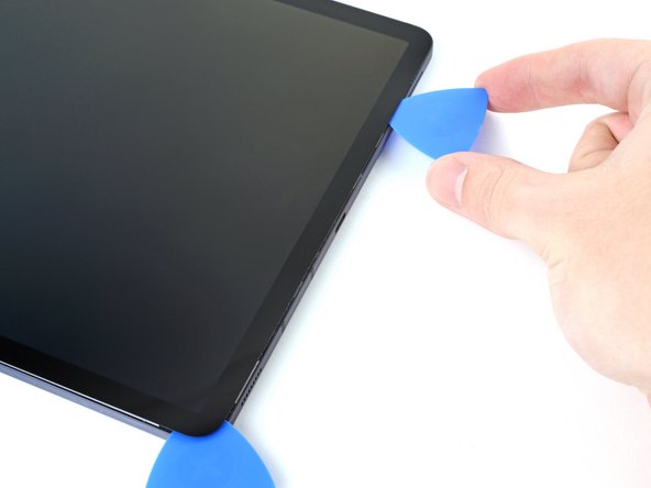
– Gently slide a new opening pick into the gap you made.
– Now, glide that pick smoothly along the top edge of your device, aiming for the top-left corner.
Step 11

– Heat up an iOpener and gently press it against the left edge of the device to soften the glue underneath. This will help loosen things up and make the next steps easier. If you need help, you can always schedule a repair.
Tools Used
Step 12

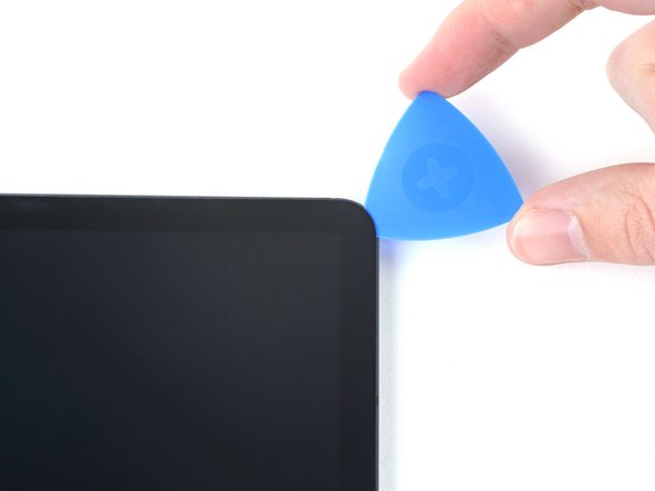
– Swing that opening pick smoothly around the top-left corner—think of it as giving your device a stylish new part.
– Let the opening pick chill right there to keep that sticky adhesive from making a comeback.
Step 13


– Pop in a fresh opening pick into the gap you’ve created. Time to make some space!
– Gently slide that pick along the left edge of the device, gliding towards the bottom-left corner. You’re almost there!
Step 14


At this stage, the screen’s edge should be free from the frame. If you’re still feeling some resistance around the corners, grab an opening pick and gently cut through any remaining adhesive. Keep at it—you’re getting there!
– Twist that opening pick around the bottom-left corner of your device with finesse.
– Keep the pick snugly in place to stop that pesky adhesive from sealing up again.
Step 15


Don’t go all the way with removing the screen just yet – it’s still hanging on to the frame with a flex cable.
Be careful not to twist or pull the screen too far from the frame, or that flex cable might not be happy!
– With the screen facing up, gently lift it away from the device as if you’re flipping open a book—easy does it!
– Lay the screen upside down and keep it parallel to the frame before moving on to the next step.
– During reassembly, it’s smart to power on your tablet temporarily to check that everything’s working properly before sealing it back up.
– Make sure to fully power down your tablet before continuing with reassembly.
– Use tweezers or your fingers to carefully remove any stubborn adhesive bits. For stubborn residue, a bit of high-concentration (over 90%) isopropyl alcohol can do wonders for cleaning up leftover glue.
– If you’re working with custom-cut adhesives, follow the specific instructions for them. If you’re using double-sided tape, refer to its guidelines for best results.
Tools Used

Step 16

– Grab the flat end of a spudger and gently pry up the display cable’s press connector from the screen—think of it as giving it a little lift. When you’re ready to reconnect, align the press connectors carefully and press down on one side until it clicks, then do the same on the other side. Avoid pressing in the middle to prevent bending the pins and causing damage. If you need a hand, you can always schedule a repair.
Tools Used

Step 17

– Gently grip the display cable with tweezers or your fingers to hold it steady during the process.
– Carefully use the flat end of a spudger to lift and disconnect the fingerprint sensor’s press connector from the display cable.
– Note the way the display cable is positioned; you’ll want to bend it the same way when attaching a new screen.
Step 18


– Gently detach the screen from its frame and set it aside. You’ve got this!
Step 19


– Grab a Phillips #00 screwdriver and get ready to remove fifty 3mm-long screws that hold the frame bracket to the frame. The third photo shows these screws marked by quadrant—use it during reassembly to keep track of all the screws: bottom left = 9 screws, bottom right = 14 screws, top right = 12 screws, and top left = 15 screws. Take your time, stay organized, and if you need help, you can always schedule a repair.
Tools Used

Step 20
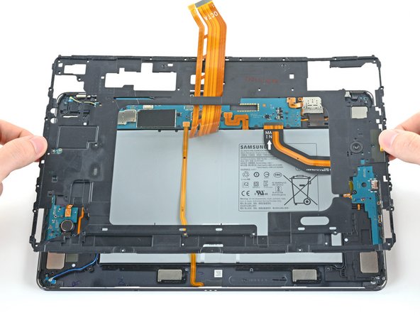


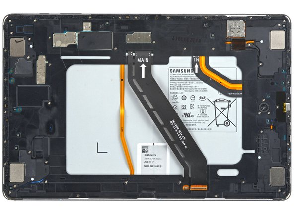
– Gently lift the frame bracket off the frame, but don’t forget to carefully guide that display cable through its socket as you go!
Step 21

– Grab the flat end of your spudger and gently pop up the battery’s press connector from the motherboard. Easy does it!
Tools Used
Step 22

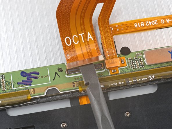
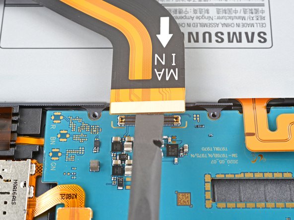
– Grab your trusty spudger and gently lift the display cable’s press connector off the motherboard. Don’t be shy—just a little pry should do the trick!
– Now, let’s do the same for the fingerprint sensor cable connected to that display cable. A quick and easy lift and you’re good to go!
Tools Used
Step 23

– Gently lift and peel back the display cable using your fingers, taking care not to damage any surrounding parts. If you need help, you can always schedule a repair.
Step 24

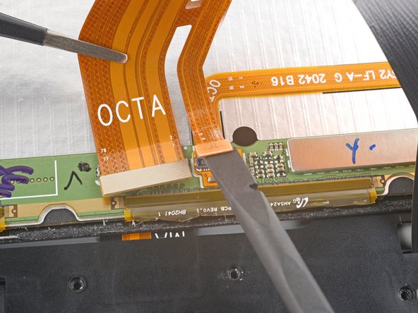
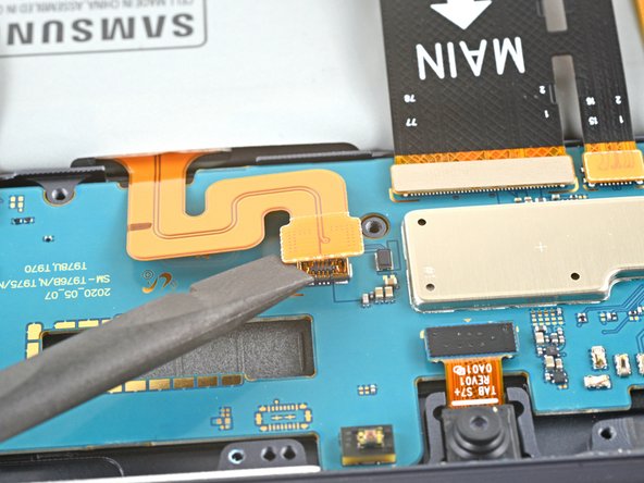
– Grab the flat end of your spudger and gently pop up the press connector for the daughterboard interconnect cable from the motherboard. Easy does it!
Tools Used
Step 25


– Grab the flat end of your spudger and gently pop up the keyboard dock port cable’s press connector from the motherboard—like a pro unlocking secret treasure.
Tools Used
Step 26
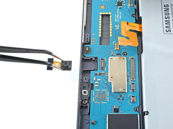

– Grab the flat end of a spudger and gently lift up to disconnect the front camera’s press connector from the motherboard. Take your time—no need to rush!
– Now, use tweezers or your fingers to carefully lift out the front camera. It should come right out with a little nudge!
Step 27

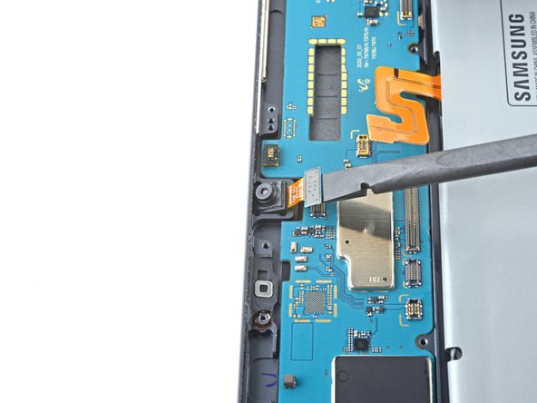
– Take the flat end of your spudger and gently pop up the microSD card reader’s connector from the motherboard. Easy does it—just a little wiggle and you’re good!
Tools Used
Step 28

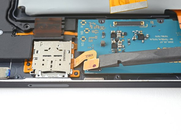
– Grab your trusty spudger and gently slide the flat end underneath the rear camera’s two press connectors. Give it a little lift to disconnect them from the motherboard with finesse!
Tools Used
Step 29

– Grab the flat end of a spudger and gently pry up the power button cable’s press connector from the motherboard. Keep it cool and steady—you’re doing great! If you need help, you can always schedule a repair.
Tools Used
Step 30

Be careful not to puncture or bend the battery with your tool—a damaged battery could leak harmful chemicals or even start a fire. If you need help, you can always schedule a repair.
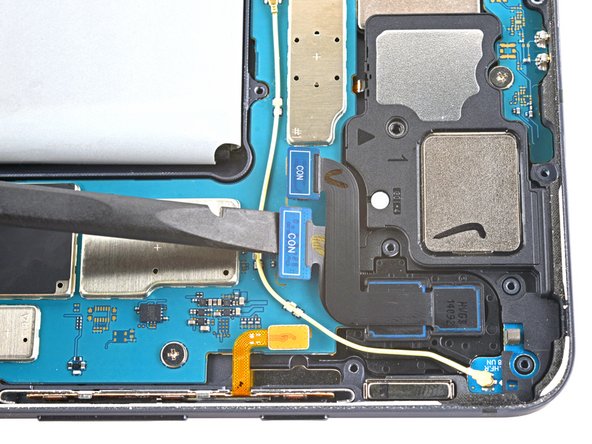
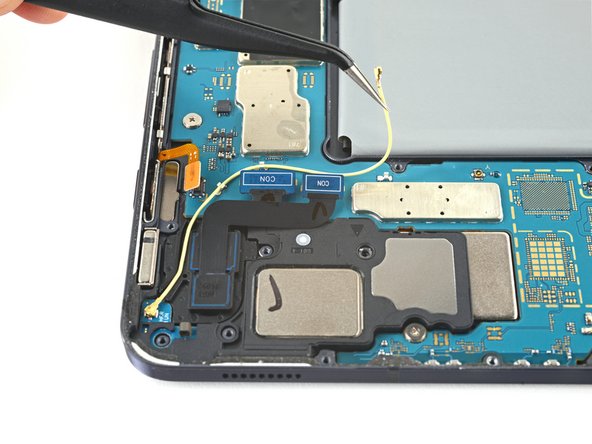
– Gently use the tip of a spudger to lift and unplug the yellow coaxial cable from the bottom-right loudspeaker on the motherboard.
– When putting it back together, these connectors can be a bit sneaky. Take them one at a time, line up each connector over its socket, and press down firmly with the flat end of your spudger until you hear a satisfying click.
Tools Used
Step 31
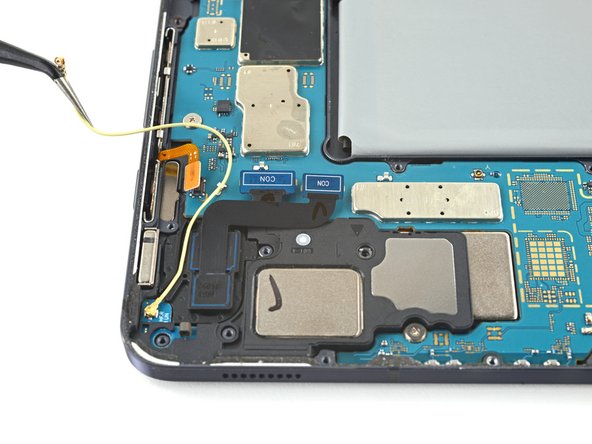

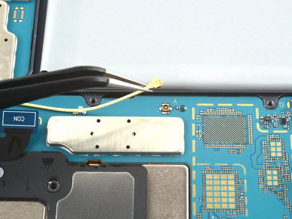
– Gently detach the coaxial cable from the frame, making sure to completely unthread it from the motherboard. If you need help, you can always schedule a repair.
Step 32

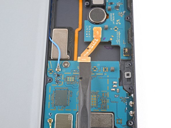
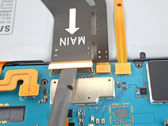
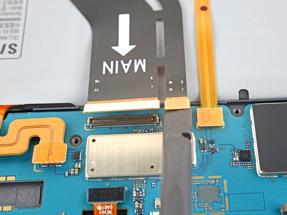
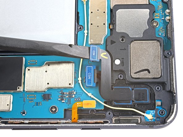
– Grab the flat end of a spudger and gently pry up the press connector holding the interconnect cable to the motherboard. Keep it cool and steady—you’re doing great! If you need help, you can always schedule a repair.
Tools Used
Step 33
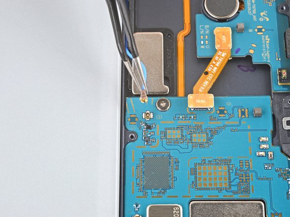

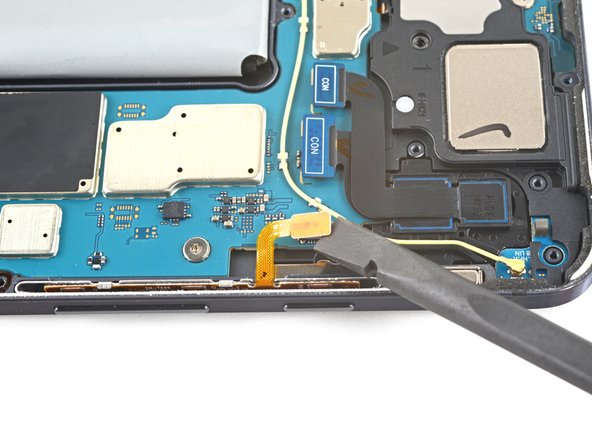
– Grab a spudger and gently work your way under the blue coaxial cable for the top-right loudspeaker. Carefully lift and disconnect it from the motherboard—no rush, take your time!
Tools Used
Step 34

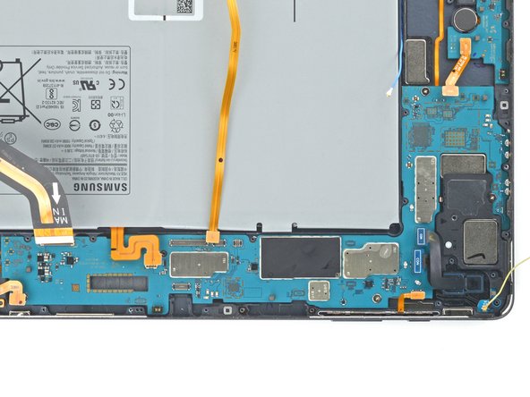
– Grab your Phillips #00 screwdriver and remove the three 2 mm screws holding the motherboard in place.
Tools Used
Step 35
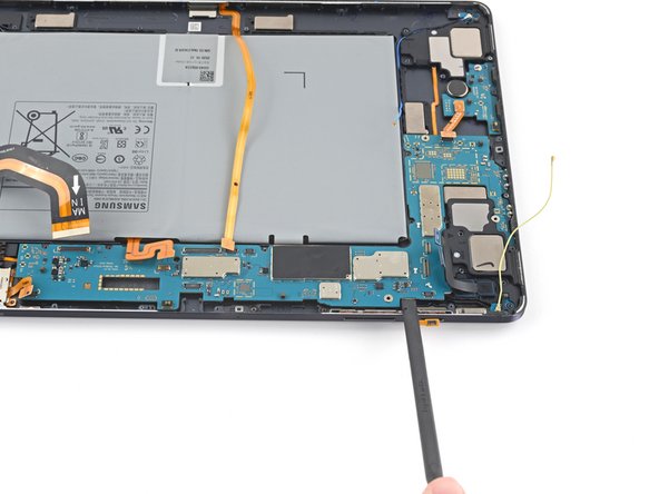

– Gently slip a spudger into the gap between the motherboard and the frame.
– Give the spudger a little nudge to release the motherboard from its clips. A little prying goes a long way!
– Carefully lift out the motherboard. Easy does it!
– When putting everything back together, start by screwing in the motherboard to get it properly aligned. Once it’s in place, reconnect the cables to finish the job.
Tools Used
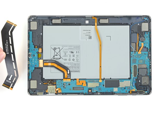
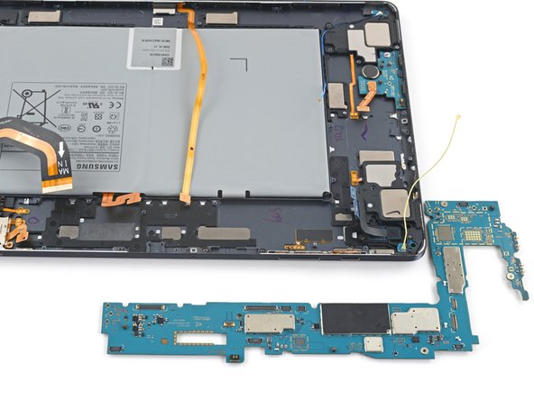
Step 36

– Now, you’ve got the motherboard all to yourself!
Success!
