Step-by-Step Guide: Nintendo Switch Lite LCD Replacement
Duration: 45 minutes
Steps: 65 Steps
Let’s get your Nintendo Switch Lite back in action by swapping out its faulty or busted LCD. The Switch Lite uses JIS screws, but hey, if you’ve got a Phillips screwdriver lying around, it’ll work just fine in a pinch. Just be super careful not to strip those little guys. Note: This guide is for the LCD only. If you’re tackling the whole screen (which includes the LCD attached to the digitizer), check out a different guide. If your display glass is cracked but the LCD still shines, you’re looking at a digitizer replacement instead. Bonus tip: You don’t have to remove the joysticks and buttons, but trust us, it’ll make your life a whole lot easier. One more heads-up: You’ll need to take off the shield plate and heat sink. Remember to clean off the old thermal paste from both components and the CPU, then reapply some fresh paste before putting it all back together. You’ve got this!
Step 1

Before diving into this repair adventure, be sure to completely power down your device.
As you tackle this repair, keep an eye on each screw and make sure it finds its way back to its original home. You’ve got this!
– Grab a Y00 screwdriver and pop out the four 6.3 mm screws keeping the back panel in place.
Step 2


To keep those pesky screws from getting stripped, press down firmly, take your time, and if they’re being stubborn, try switching up your screwdriver. You’ve got this!
– Grab your JIS 000 driver or an official PH 000 driver and let’s get those screws out. Start by unscrewing the following to detach the back panel:
– Two 3.6 mm screws located at the top of the device
– Two 3.6 mm screws at the bottom of the device
Step 3


Be gentle with that opening tool—no need to dig in too deep or you’ll risk messing up the speaker module.
– Slide an opening tool into the left speaker grille at the bottom of the device—careful now, it’s all about finesse here.
– Give the tool a little twist to pop those clips loose and set the back panel free.
Step 4


– Glide your opening tool around the bottom-left corner and release those clips on the left side like a pro!
Step 5


Hey there, keep it cool—don’t push the opening tool too far, or you might risk messing up the speaker module!
– Use an opening tool and gently slide it into the right speaker grille at the bottom of your device.
– Give the tool a little twist to pop those clips free.
Step 6


– Glide the opening tool around the bottom-right corner and pop those clips on the right side of the device.
Step 7


– Keep gliding and gently prying that opening tool along the top gap of your device to pop those clips loose! You’re doing great!
Step 8


– Gently lift the bottom edge of the back panel, just like you’re opening a book to your favorite chapter.
– Carefully take off the back panel and set it aside.
Step 9

– Grab a trusty JIS 000 driver or a PH 000 driver and unscrew these four little guys:
– Three 3.1 mm screws
– One 4.5 mm screw
Step 10


You might notice a little pushback here, and that’s totally cool! The shield plate is just a bit snug against the heat sink thanks to some thermal paste bonding them together.
– Grab your trusty spudger or just your fingers to gently lift that shield plate right out of the device.
– Say goodbye to the shield plate as you remove it.
– Time for a little cleanup! Use some isopropyl alcohol and a microfiber cloth to wipe away the old thermal paste from both the shield plate and heat sink. Don’t forget to apply a fresh layer of thermal paste to the heat sink before putting everything back together!
Tools Used


Step 11


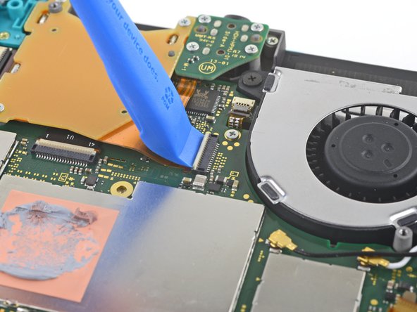
– Grab your trusty opening tool or just your fingernail and gently lift that little hinged locking flap on the ZIF connector for the motherboard interconnect cable. You’ve got this!
Step 12


Hey, steer clear of metal tweezers! They can mess things up by short-circuiting the ribbon cable or connector. Nylon-tipped or ceramic-tipped tweezers are the safer, smarter choice here.
– Grab your tweezers and gently wiggle that interconnect cable out of its cozy little spot on the motherboard. You’ve got this!
Tools Used

Step 13


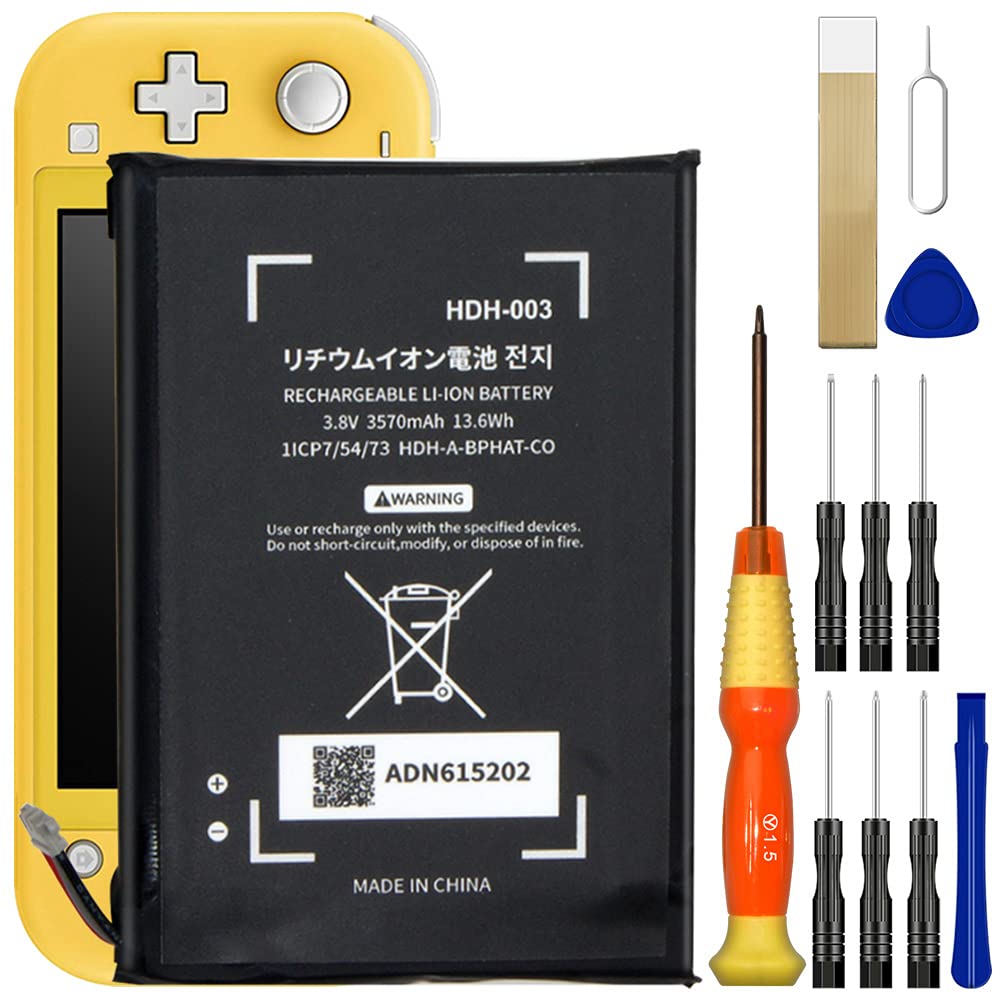
– Gently use the tip of a spudger to lift the battery connector straight up and out of its cozy little home on the motherboard.
Tools Used
Step 14

Just peel back the foam a bit until you clear the fan.
– Gently use the flat end of a spudger or your fingers to lift and peel away the foam that’s lightly sticking to the fan—take your time, no rush!
Tools Used
Step 15

– Grab a JIS 000 driver or an official PH 000 driver from your toolkit and carefully unscrew those three 3 mm screws holding the heat sink snugly to the motherboard. You’ve got this!
Step 16


You might notice a bit of pushback here. Don’t worry, that’s totally normal—it’s just the heat sink being slightly stuck to the CPU by the thermal paste.
– Grab a spudger or just your trusty fingers and gently lift that heatsink off the motherboard. It’s time to set it free!
– Next up, let’s tidy things up! Use some isopropyl alcohol and a microfiber cloth to wipe away the old thermal paste from both the heatsink and CPU. Once that’s all clean, don’t forget to apply a fresh layer of thermal paste to the CPU before putting everything back together.
Tools Used
Step 17

– Grab your opening tool or just your trusty fingernail, and gently lift up the tiny, hinged locking flap on the ZIF connector for the game card reader cable. Easy does it!
Step 18

– Grab a JIS 000 driver or a PH 000 driver and unscrew the seven 3.1 mm screws holding down the game card reader and headphone jack. Let’s get those little guys out of the way!
Step 19


– Grab some tweezers or use your fingers, and gently lift the game card reader. Wiggle it to the left like you’re shimmying at a dance party, and slide that cable out of its connector.
– Take out the game card reader and the headphone jack. Easy peasy!
Tools Used
Step 20

– Grab a JIS 000 driver or a PH 000 driver and unscrew the two 4.5 mm screws holding the right trigger button assembly to the motherboard. Easy does it!
Step 21


– Take off the right trigger button assembly. It’s a small step, but it makes a big difference, so go ahead and give it a little attention.
Step 22
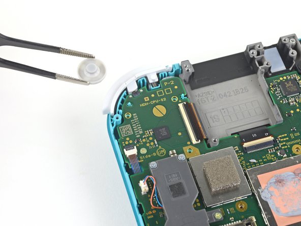

– Grab a pair of tweezers or use your fingers to pluck off the right trigger button assembly’s rubber pad if it didn’t stick to the button assembly.
Tools Used
Step 23

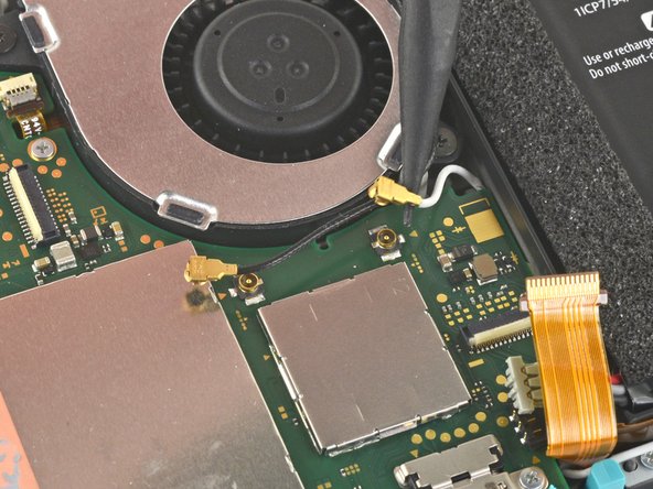

– Grab your trusty spudger and gently pop the black antenna cable straight out of its snug little socket on the motherboard—it’s easier than it sounds, promise!
– Now give the white antenna cable the same treatment—steady hands win the race here!
Tools Used
Step 24

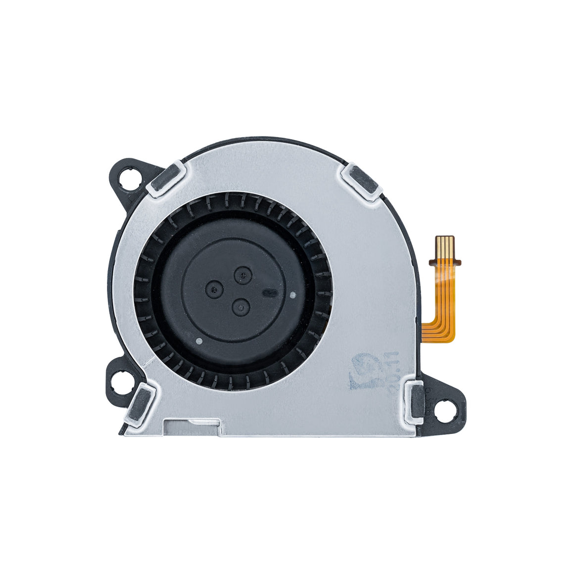
– Grab your trusty opening tool or just your fingernail and gently lift that little hinged locking flap on the fan cable’s ZIF connector. You’ve got this!
Step 25


– Grab a trusty pair of tweezers and gently wiggle the fan cable out of its cozy connector on the motherboard. You’ve got this!
Tools Used
Step 26


– Time to get started! Use an opening tool or your fingernail to carefully flip up the tiny, hinged locking flap on the screen cable’s ZIF connector. Take your time and be gentle, we’ve got this!
Step 27


– Grab your trusty tweezers and gently wiggle the screen cable out of its connector on the motherboard. Take your time—precision is key!
Tools Used
Step 28


– Grab an opening tool or use your trusty fingernail to pop up the little hinged locking flap on the digitizer cable’s ZIF connector. You’re doing great—keep going!
Step 29


– Carefully use a pair of tweezers to gently coax the digitizer cable out of its connector on the motherboard. If it’s being stubborn, don’t worry, it’s supposed to be a bit tricky – just be patient and take your time.
Tools Used
Step 30


– Grab your trusty opening tool or just your fingernail, and carefully flip up that tiny hinged locking flap on the ZIF connector for the right joystick cable. Take your time—precision is key!
Step 31


– Carefully use a pair of tweezers to gently coax the right joystick cable out of its connector on the motherboard. If it’s being stubborn, don’t worry – it’s supposed to come out, and a little patience will do the trick!
Tools Used
Step 32

– Grab your trusty JIS 000 driver or the official iFixit PH 000 driver and let’s get to work! Start by removing the six screws that are holding the motherboard in place:
– Three screws measuring 3.1 mm
– Three screws measuring 4.5 mm
Step 33

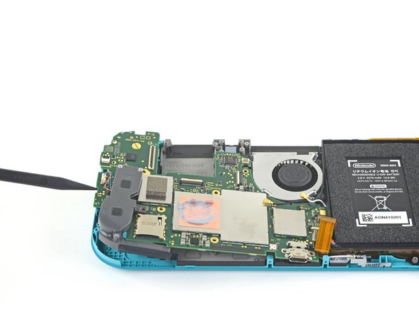

– Gently wedge a spudger between the frame and motherboard, then carefully lift the motherboard up and out of its snug little home.
– Now, it’s time to remove the motherboard assembly. You got this!
Tools Used
Step 34

– Grab your JIS 000 or PH 000 screwdriver and unscrew those two 3.5 mm screws holding the joystick in place. Easy peasy, let’s keep it going!
Step 35


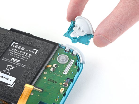
There’s a slim black gasket snug around the hole where the joystick peeks through the frame. Be gentle and keep it chill while removing the joystick so the gasket stays happy and in place!
– Gently wiggle and lift the joystick out using your fingers—it’s like pulling off a snug cap, super easy!
Step 36


Handle those wires with care! Tugging on them might just send them flying off the connector. Keep it gentle, and you’ll be golden!
– Grab a trusty pair of tweezers or just your fingers, and gently lift that left speaker cable straight up and out of its cozy socket on the daughterboard. You’ve got this!
Tools Used
Step 37

– Grab a JIS 000 driver or an official PH 000 driver from iFixit and carefully unscrew the 4.5 mm screw that’s holding the left speaker module in place. You’ve got this!
Step 38


Be cautious as you tackle this step! There’s a delicate ribbon cable hiding underneath part of the speaker module. Make sure you don’t snag the speaker module on the cable while you’re gently removing it. You’ve got this!
– Gently lift the speaker module with your fingers and carefully pop it out of its little home to remove it.
Step 39


– Grab an opening tool or your trusty fingernail and gently flip up that tiny, hinged locking flap on the ZIF connector for the motherboard interconnect cable.
Step 40


– Time to get a little delicate! Use a trusty pair of tweezers to carefully slide the motherboard interconnect cable out of its connector on the daughterboard.
Tools Used
Step 41


– Grab your opening tool or just use your fingernail to gently flip up those tiny, hinged locking flaps on the two ribbon cable ZIF connectors. Take it slow and steady—you’re doing awesome!
Step 42


– Grab a trusty pair of tweezers and gently wiggle the daughterboard screen cable out of its cozy connector on the motherboard. You’ve got this!
– Now, let’s do the same for the volume buttons cable. Just a little finesse and you’ll be on your way!
Tools Used
Step 43


– Grab a pair of tweezers or use your fingers to gently pop out the volume buttons—easy does it!
Tools Used
Step 44


– Grab your trusty opening tool or just your fingernail, and gently flip up the hinged locking flap on the ZIF connector for the left joystick cable. Easy does it—no rush, just a delicate touch!
Step 45


– Grab a pair of tweezers and carefully wiggle the left joystick cable out of its connector on the daughterboard—nice and easy, no rush!
Tools Used
Step 46

– Grab a JIS 000 driver or a trusty PH 000 driver and get to work on those two 4.5mm screws holding down the left trigger button assembly. Once they’re loose, you’re one step closer to success!
Step 47

– Take off the left trigger button assembly with care.
Step 48

– Let’s get started by removing the screws! Use a JIS 000 driver or an official PH 000 driver to take out the following four screws:
– You’ll need to remove two 4.5 mm screws – easy peasy!
– Next, remove two 6 mm screws. You’re doing great!
Step 49


– Gently coax the daughterboard upwards with your fingers, sliding it out of its cozy spot to free it completely.
Step 50

– Grab your trusty JIS 000 driver or the official iFixit PH 000 driver, and let’s get ready to rock! Carefully remove those two 3.5 mm screws that are holding the left joystick in place. You’re doing great!
Step 51


Be careful as you tackle the joystick removal! There’s a delicate black gasket snugly sitting around the hole where the joystick peeks through the frame. It’s best to leave this little guy undisturbed while you work your magic.
– Grab your trusty spudger and gently nudge the joystick up and out of its cozy little spot.
– Now, use your fingers to pop that joystick right out.
Tools Used
Step 52

– Grab your trusty JIS 000 driver or a PH 000 driver—whichever feels right—and unscrew these four little guys:
– Three screws, each 2.5 mm
– One screw standing tall at 6 mm
Step 53


– Gently use a spudger or your fingers to lift the midframe assembly out of its snug spot.
– Now, carefully remove the midframe assembly and set it aside.
Tools Used
Step 54


Here’s a couple of pics to guide you along.
– Now’s the time to remove all the buttons if you haven’t already, so they don’t go MIA on you. Let’s keep everything organized and make this repair a breeze!
Step 55

You can also use a hair dryer or heat gun, but play it cool—don’t roast the LCD if you’re planning to reuse it, as it’s quite sensitive to heat.
– Warm up an iOpener and place it on the back side of the LCD along the top edge for about 2 minutes to loosen things up.
Tools Used

Step 56


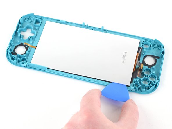
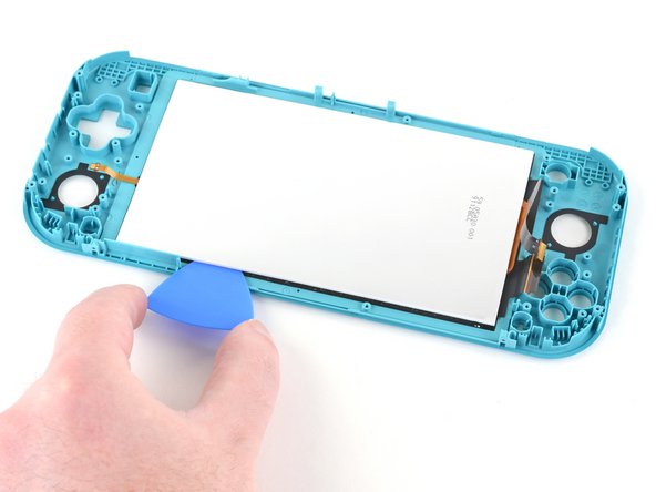
Ensure you slide that pick all the way under the LCD panel—this way, you’ll keep it safe and sound without any splits or damage!
You’ll know you’re on the right track when the silver backing starts to bubble and peel away from the white lining. Keep going, you’re doing great!
– Slide an opening pick between the frame and the top edge of the LCD to kick off the separation of these two parts. You’re doing great!
Step 57

– Gently slide the opening pick along the top edge of the LCD to break through the adhesive. Take your time, and don’t rush it!
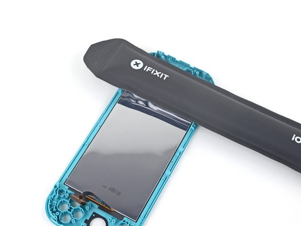
Step 58

– Warm up a trusty iOpener and press it against the backside of the LCD’s right edge for a couple of minutes. Don’t rush it—let the heat work its magic!
Tools Used
Step 59


The LCD and digitizer cables are arranged to avoid getting caught on the opening pick, but remember to take it easy while sliding the pick along the gap. A little caution goes a long way!
– Keep sliding that opening pick around the right edge of the LCD, cutting through the adhesive like a pro!
Step 60

– Take your trusty iOpener and apply some gentle heat to the back of the LCD, right along the bottom edge. Let it do its magic for about 2 minutes. You’re almost there!
Tools Used
Step 61


You’ll want to wiggle that opening pick around the edges of the LCD at different spots to navigate the frame like a pro.
– Keep sliding that opening pick along the bottom edge of the LCD—you’re slicing through adhesive like a pro!
Step 62
– Warm up that iOpener and give it a cozy hug to the back side of the LCD along the left edge for a solid 2 minutes. You’re doing great!
Tools Used
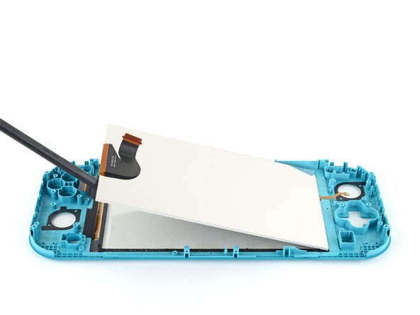
Step 63


Be careful not to catch the LCD’s daughterboard cable on the opening pick—it’s a tricky little guy!
– Keep that opening pick gliding smoothly along the left edge of the LCD to cut through the adhesive like a pro!
Step 64

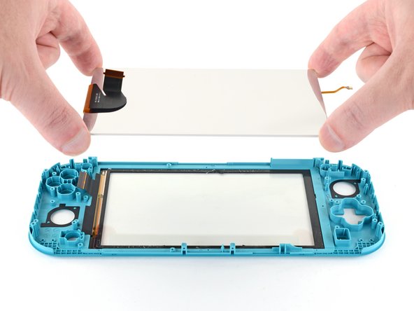
– Grab the flat end of a spudger or use your fingers to gently lift the LCD out of its frame—it’s like peeling a sticker, but cooler.
– Planning to reuse the LCD or got a new one without pre-installed adhesive? No worries—just follow this guide to slap on some pre-cut adhesive around the edges before putting it all back together.
Tools Used
Step 65


If you’re swapping out the digitizer too, feel free to breeze past this step.
– Now it’s time to put your device back together—just retrace your steps like a pro!
– Got some old tech lying around? Make sure to drop it off at an R2 or e-Stewards certified recycler.
– Things not going as smoothly as you’d hoped? No worries! Give some basic troubleshooting a shot, or swing by our Nintendo Switch Lite Answers community for a helping hand.
– And remember, if you ever find yourself in a jam, you can always schedule a repair.
Tools Used
Success!