Step-by-Step Guide to Replace iPhone 8 Back Cover
Duration: 120 min.
Steps: 50 Steps
In this photo guide, we’ll walk you through the steps to swap out the back cover of your iPhone 8 like a pro, giving your device a fresh new vibe! Remember, you’ve got this! If you need a hand or run into any hiccups, feel free to schedule a repair. Good luck with your repair adventure!
Step 1
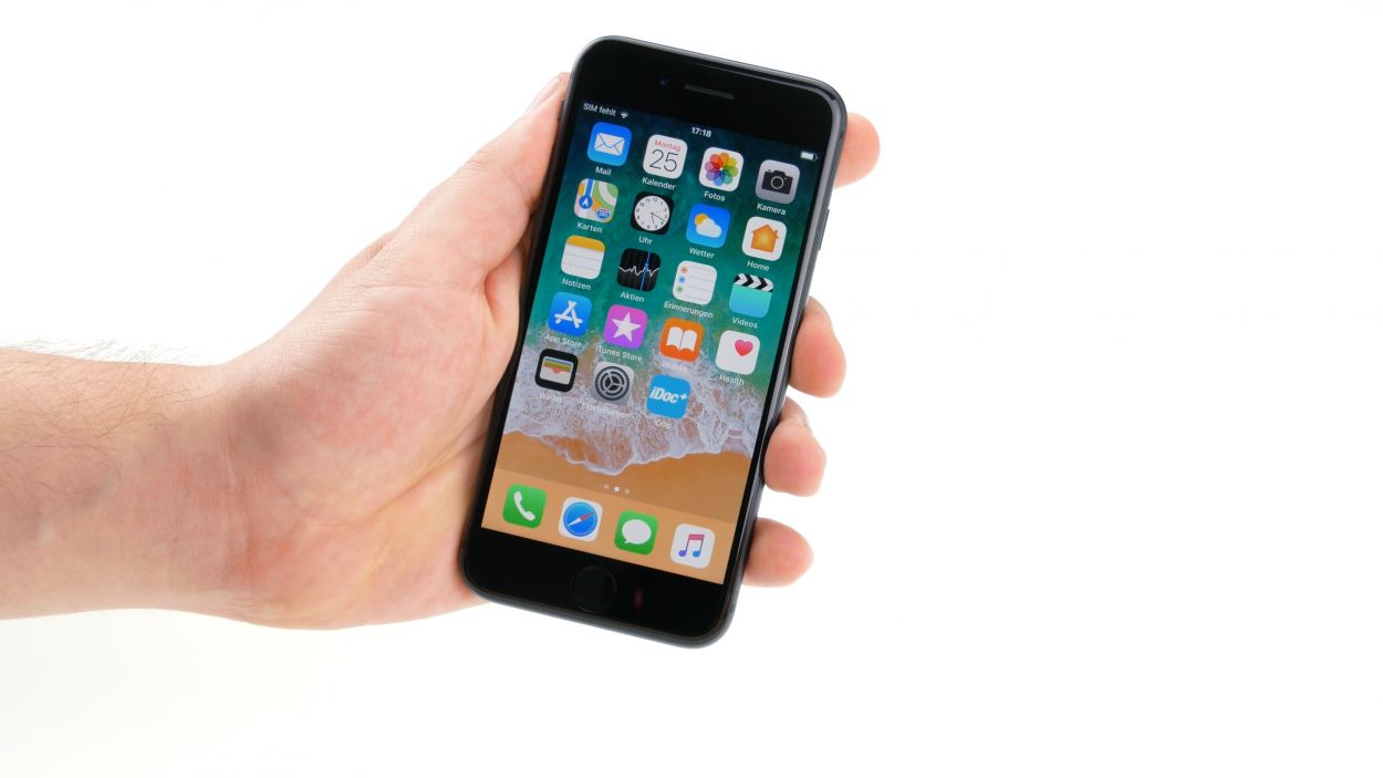
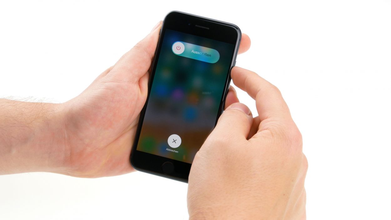
– First things first, let’s keep your iPhone safe from any pesky short circuits! Power it down completely by giving that standby button a good press for about three seconds until you see the “Turn off” slider pop up on your screen.
– Now, swipe that slider from left to right and hang tight while your iPhone takes a moment to shut down completely. You’re doing great!
Step 2

– Get those two Pentalobe screws on either side of the Lightning Connector nice and loose, then stash them away in your screw storage. We don’t want them playing hide-and-seek when it’s time to put everything back together!
2 × 3.4mm Pentalobe
To keep your screws and small parts from playing hide-and-seek, we suggest using a screw storage solution. An old sewing box can work wonders for this! Here at Salvation Repair, we love our high-quality magnetic mat, which helps us keep everything organized just like it was in your phone. Trust us, knowing where each screw goes will make your reassembly a breeze!
Tools Used
Step 3
When it comes to heating up your device, think of it like a warm hug—just enough to feel cozy, but not so hot that you’ll burn your fingers! Keep it touchable and safe, and you’ll be golden!
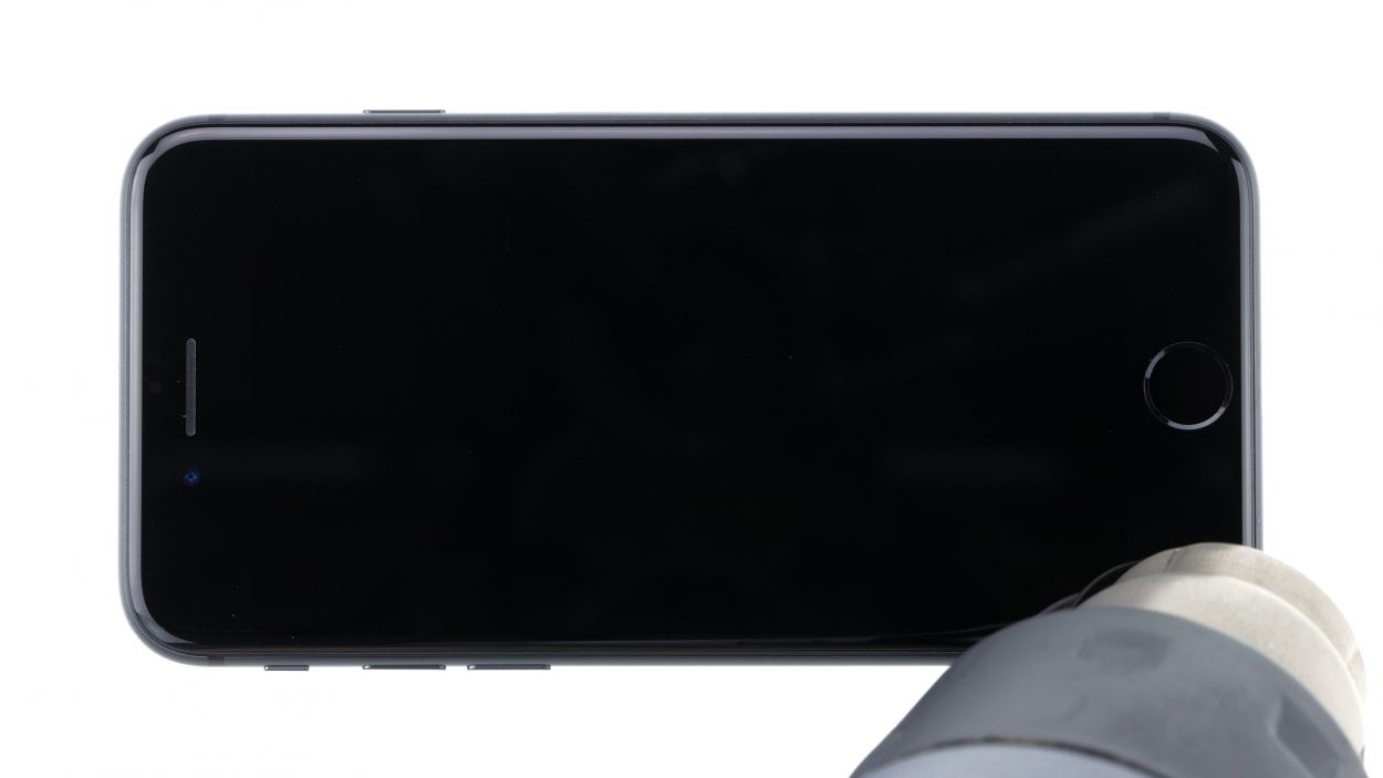
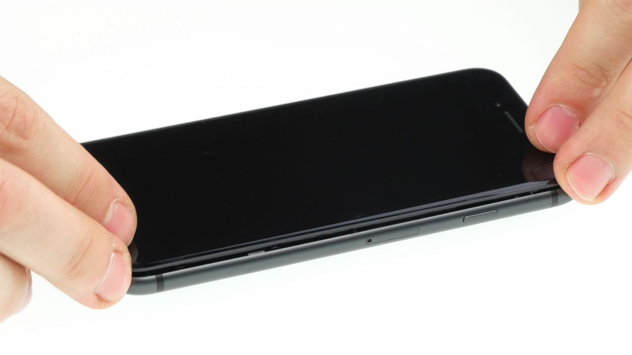
– First up, lay your iPhone 8 on a soft, clean surface to keep it scratch-free while you lift that display!
– Next, grab a hot air tool—whether it’s a hot air gun or a trusty hairdryer—and give the outer display a nice, even warm-up. You’re doing awesome!
Tools Used
- heat gun to heat parts that are glued on so they’re easier to remove.
In most cases, you can also use a hairdryer.” rel=”noopener”>Heat gun
Step 4
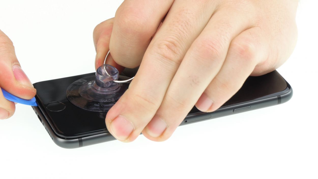
Opening up your iPhone 8 means waving goodbye to that warranty that keeps dust and splashes at bay, as well as the waterproof guarantee. So, if you’re ready for this adventure, let’s get started!
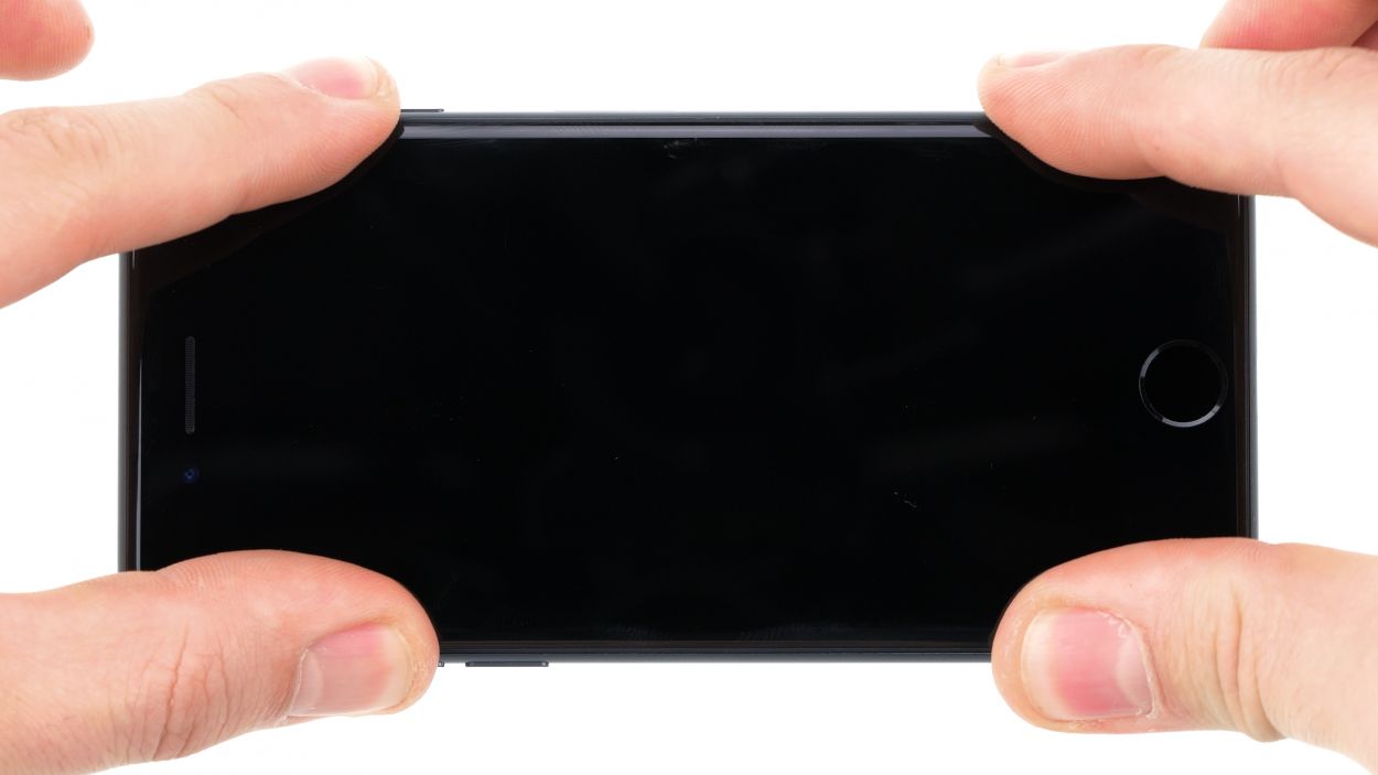
– Place a suction cup on the display just above the Home button and gently pull it upwards to create a small gap between the aluminum and display frames. You’re doing great!
– Next, slide a flat plastic tool into that snug little gap. Give it a little push to widen the gap by nudging the aluminum frame upwards. Flat plastic picks work wonders for this task!
Tools Used
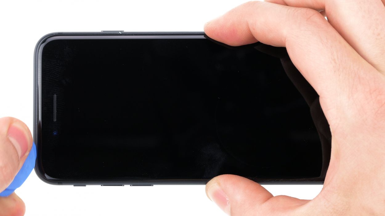
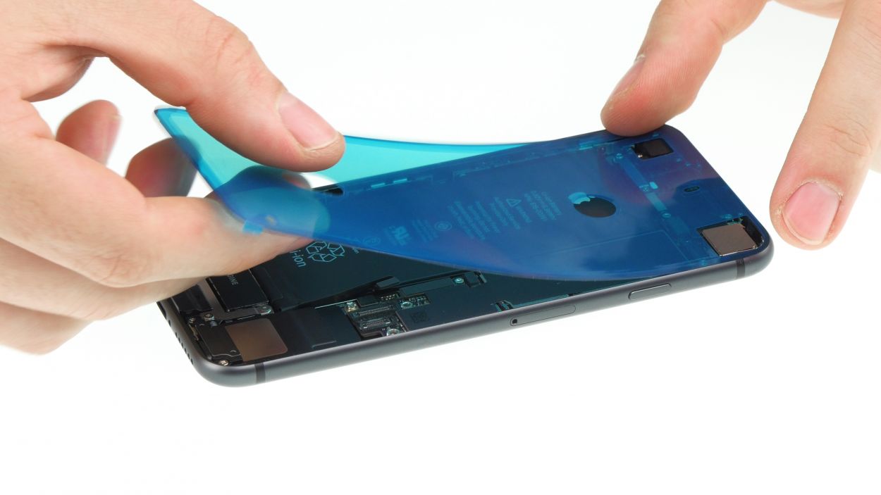
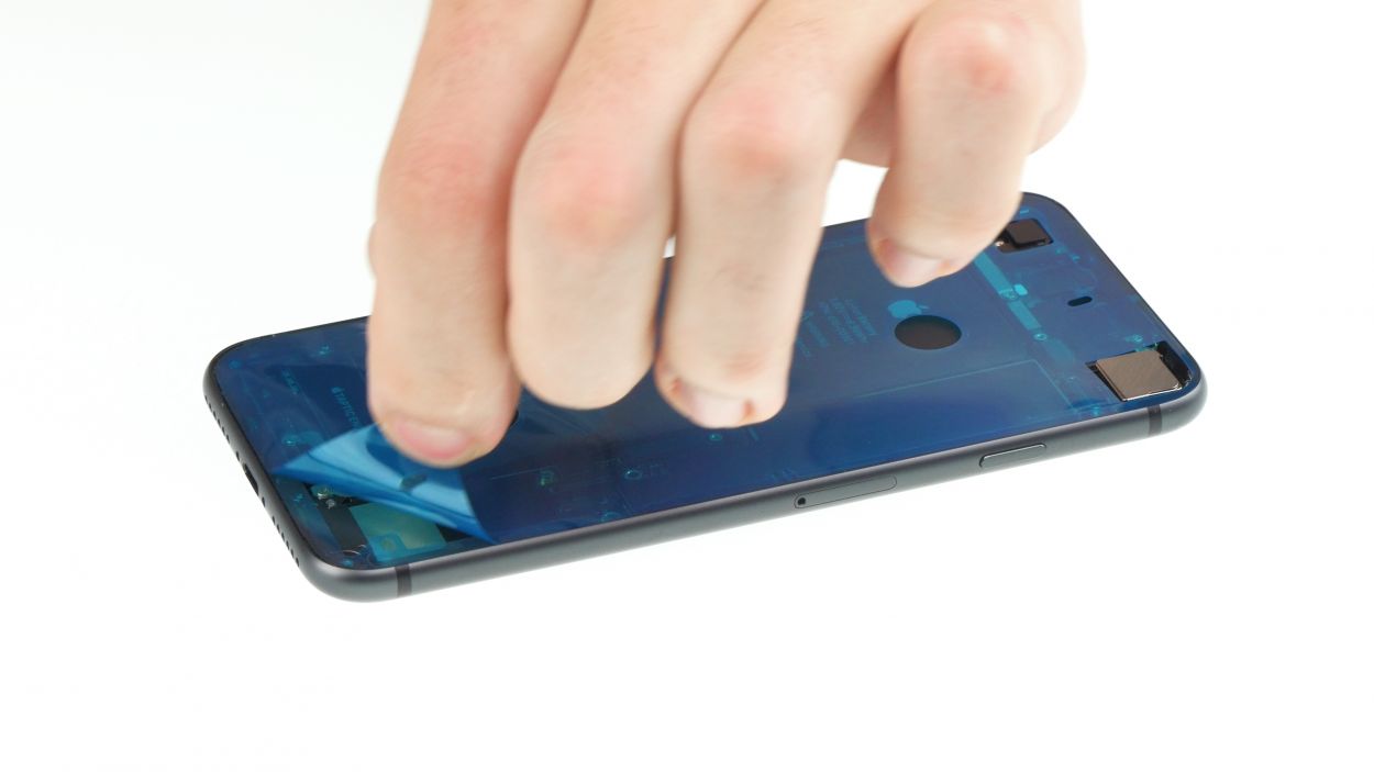
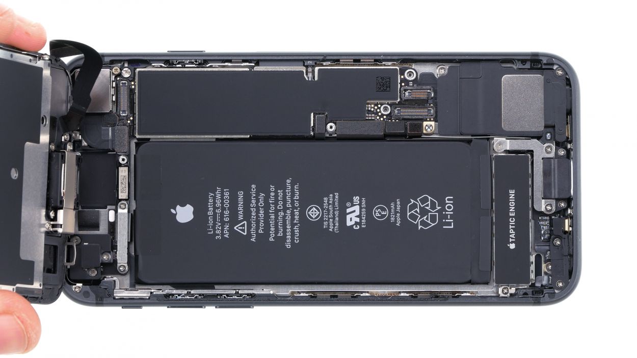
Step 5
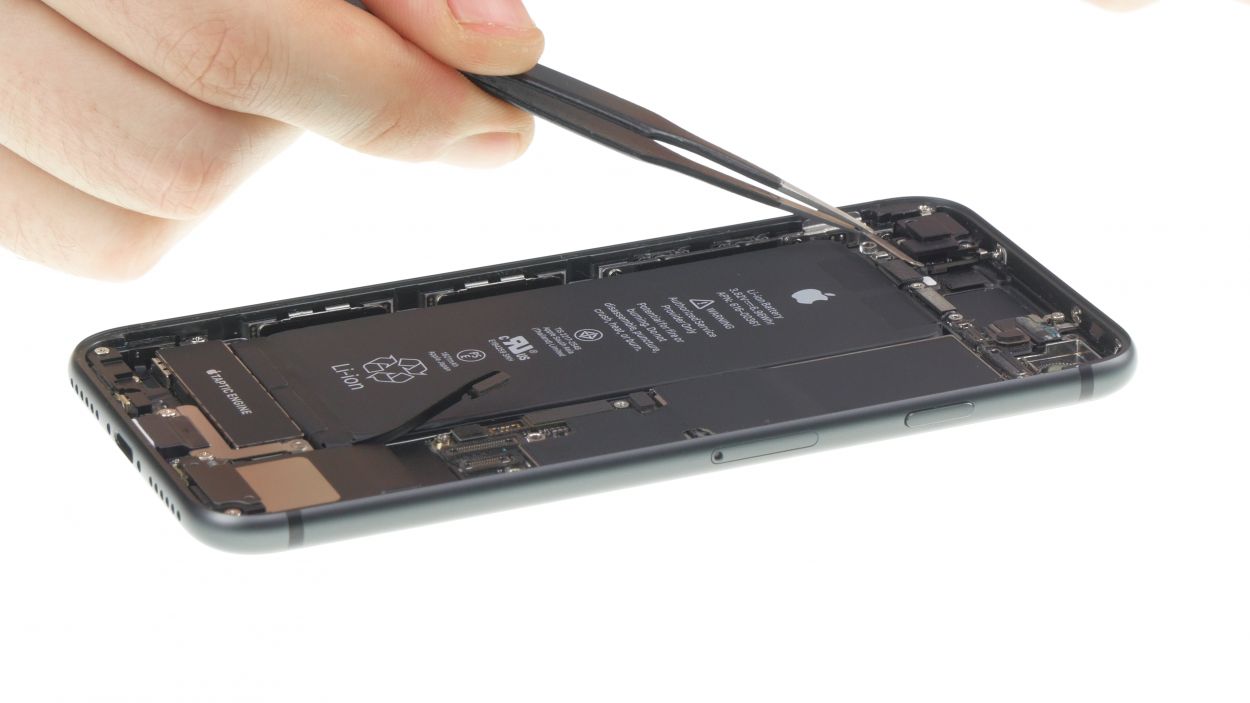
Keep it cool and collected! Don’t open the display more than 180° while it’s still connected—those delicate flex cables are counting on you to keep them safe and sound!
– Gently nudge the display upwards with your trusty plectrum to pop those lugs free from the aluminum frame. You’re on the right track!
– Now, swing it open towards the standby button like you’re unveiling a surprise! Just be sure to lean the display against something sturdy to keep those flexible cables from overstretching. You’ve got this!
Tools Used
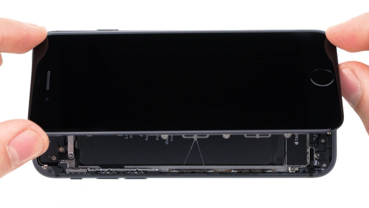
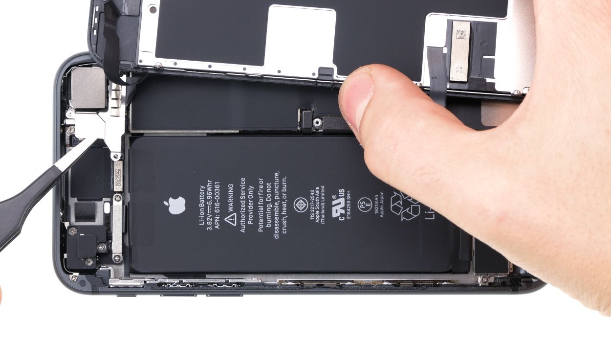
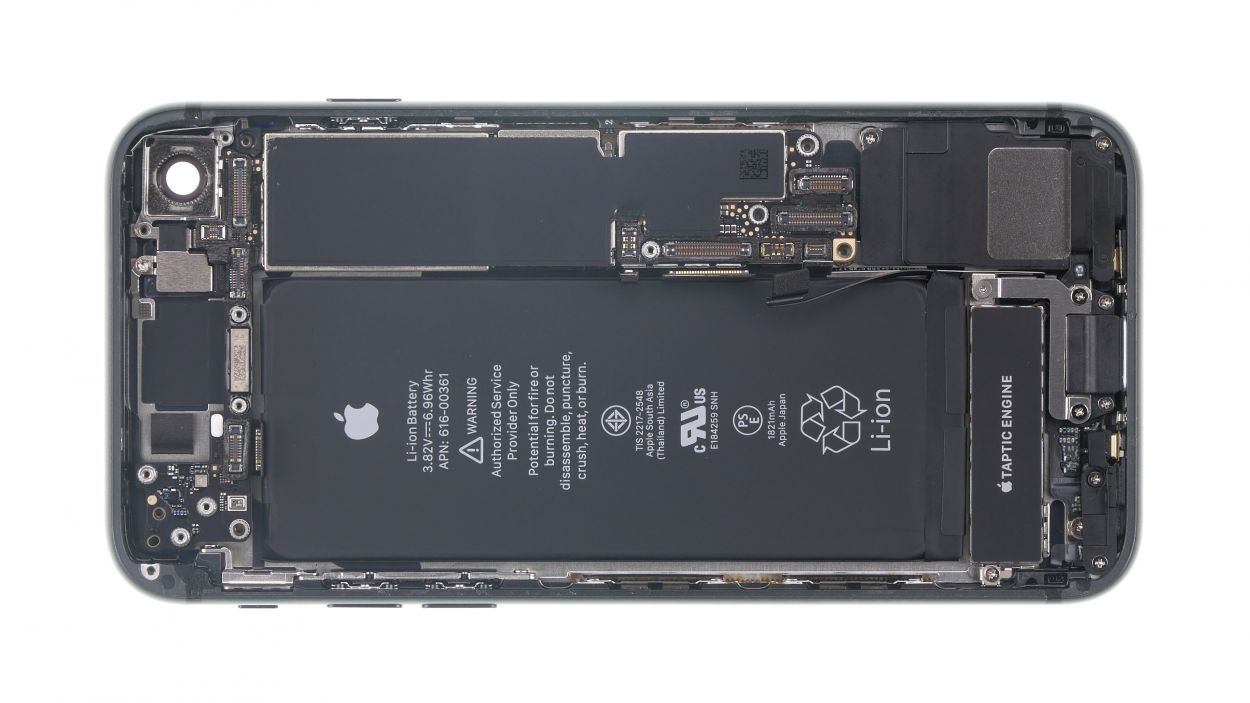
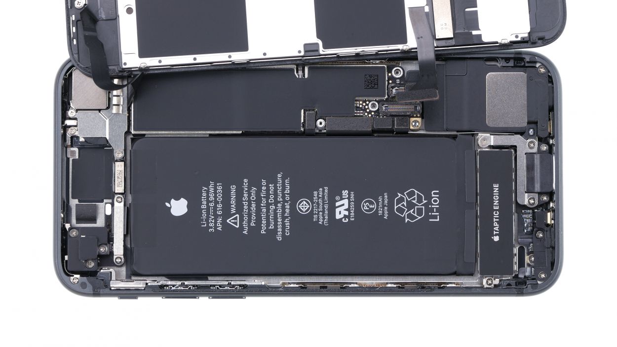
Step 6
2 × 2.6 mm Phillips
2 × 1.0 mm Phillips
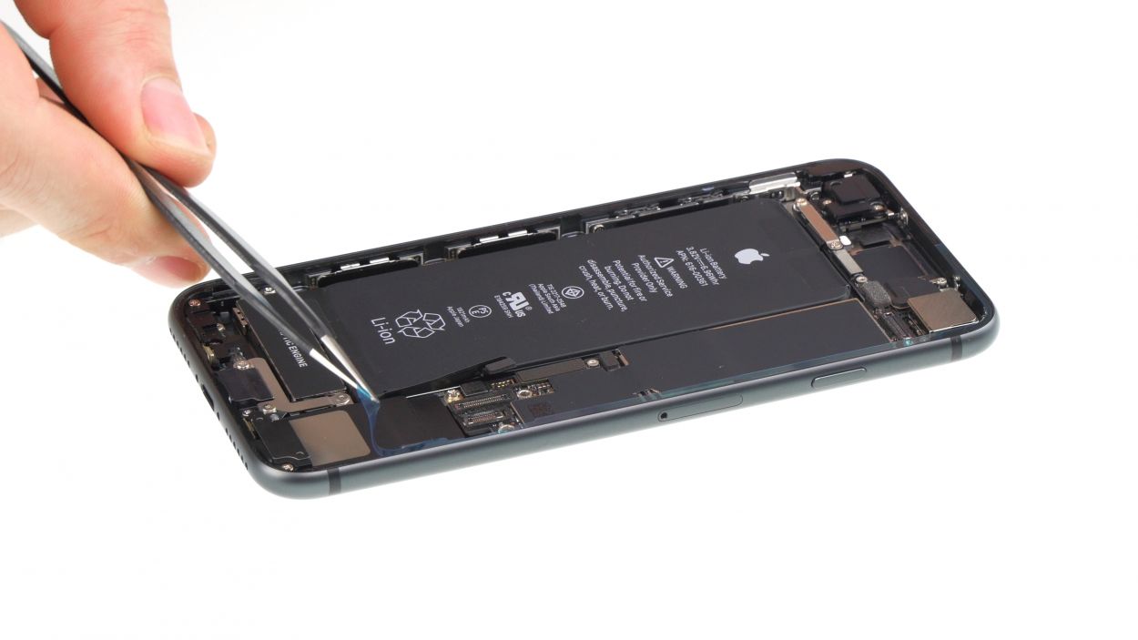
Before you dive into this repair, let’s make sure your device stays in one piece! Disconnect that battery connector to dodge any pesky short circuits and keep your device from accidentally waking up during your repair journey.
– Grab your trusty Phillips screwdriver and loosen those four screws—there are four of them, so don’t be shy! Once they’re out, gently lift off the cover using some tweezers. You got this!
– Next up, let’s disconnect that battery connector! Carefully pry it off with a plastic spudger or a lever tool. Just take your time and be gentle—you’re doing great!
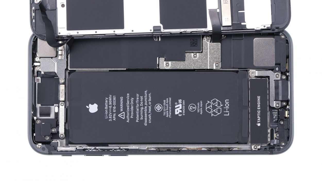
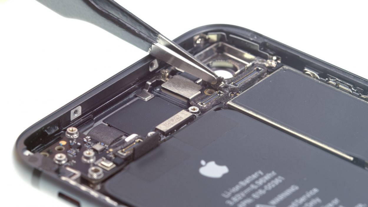
Step 7
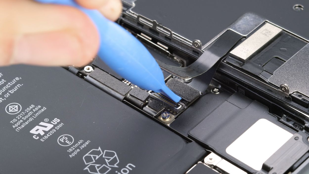
– Grab your trusty spudger and gently wiggle it to disconnect those display connectors—both the display and the home button. You’ve got this!
Tools Used
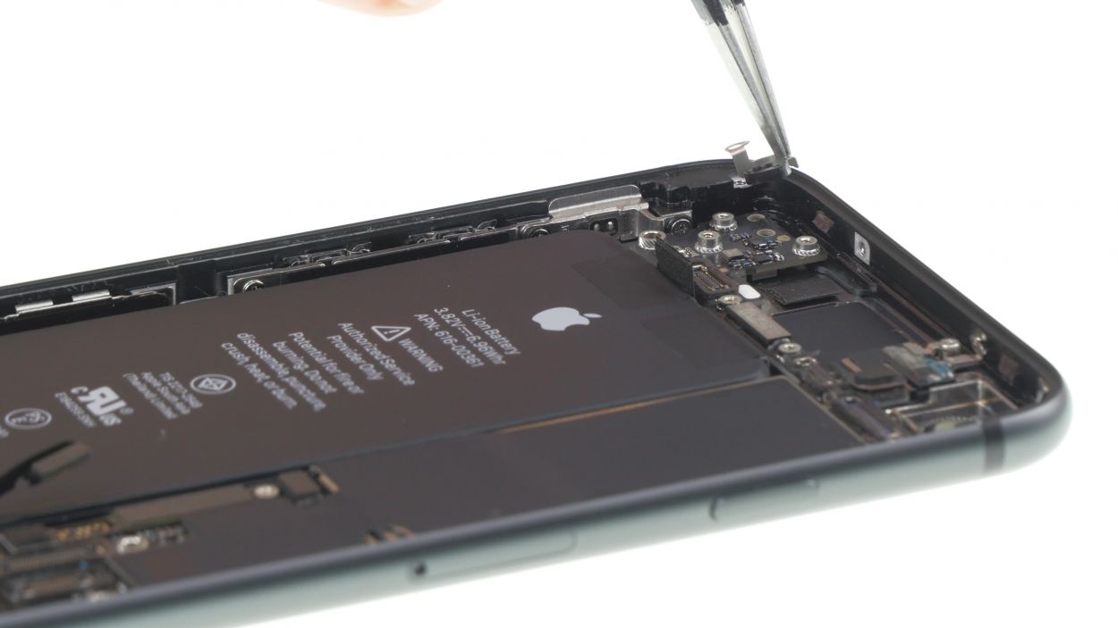
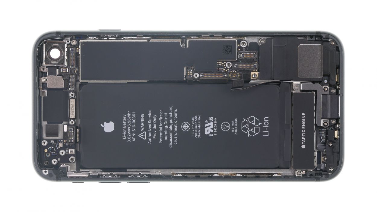
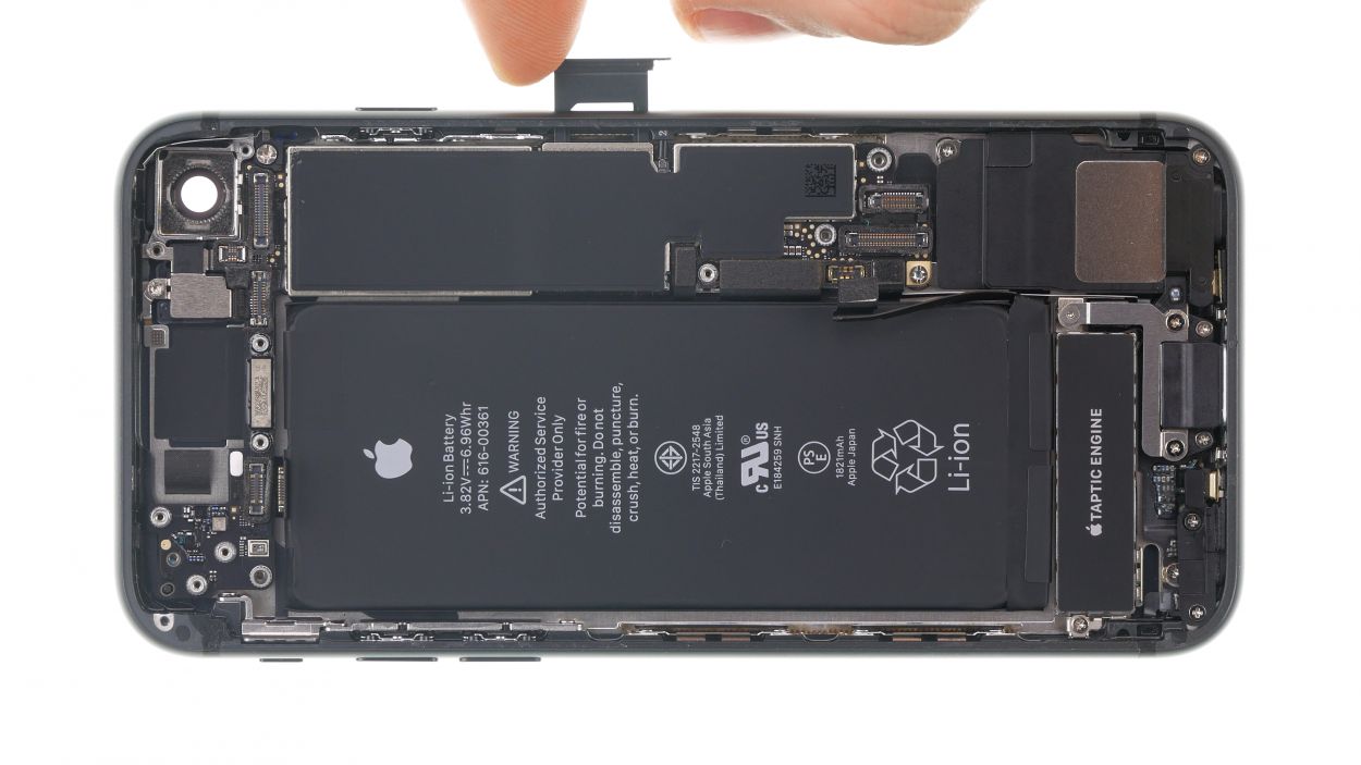
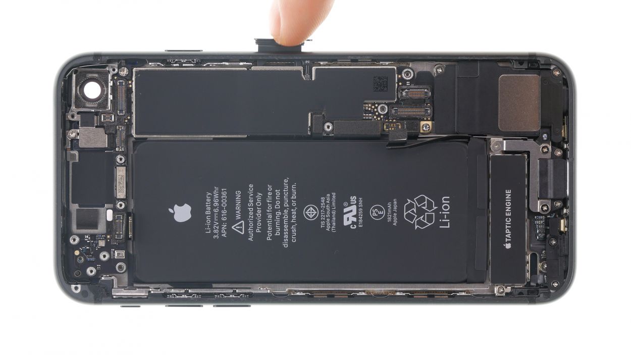
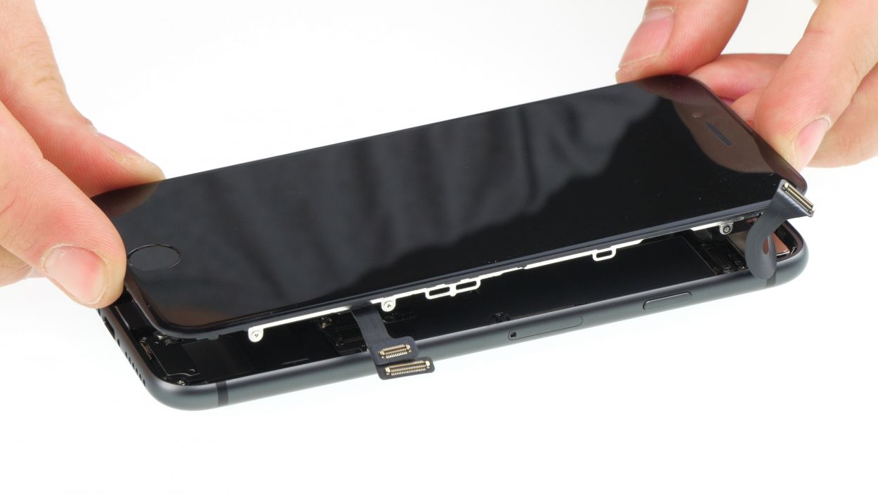
Step 8
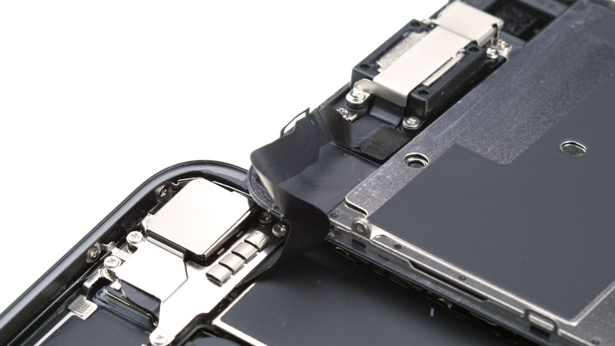
3 × 1.0 mm Phillips
– Start by unscrewing the three Phillips screws that are hanging out above the connector—give them a little twist and watch them go!
– Next, grab those tweezers and gently lift off the cover plate from your iPhone 8. You’re doing fantastic!
– Now, with a steady hand, use a spudger to carefully separate the FaceTime connector from the board. You’re almost there!
– And just like that, you can fully remove the display. Great job on making it this far!
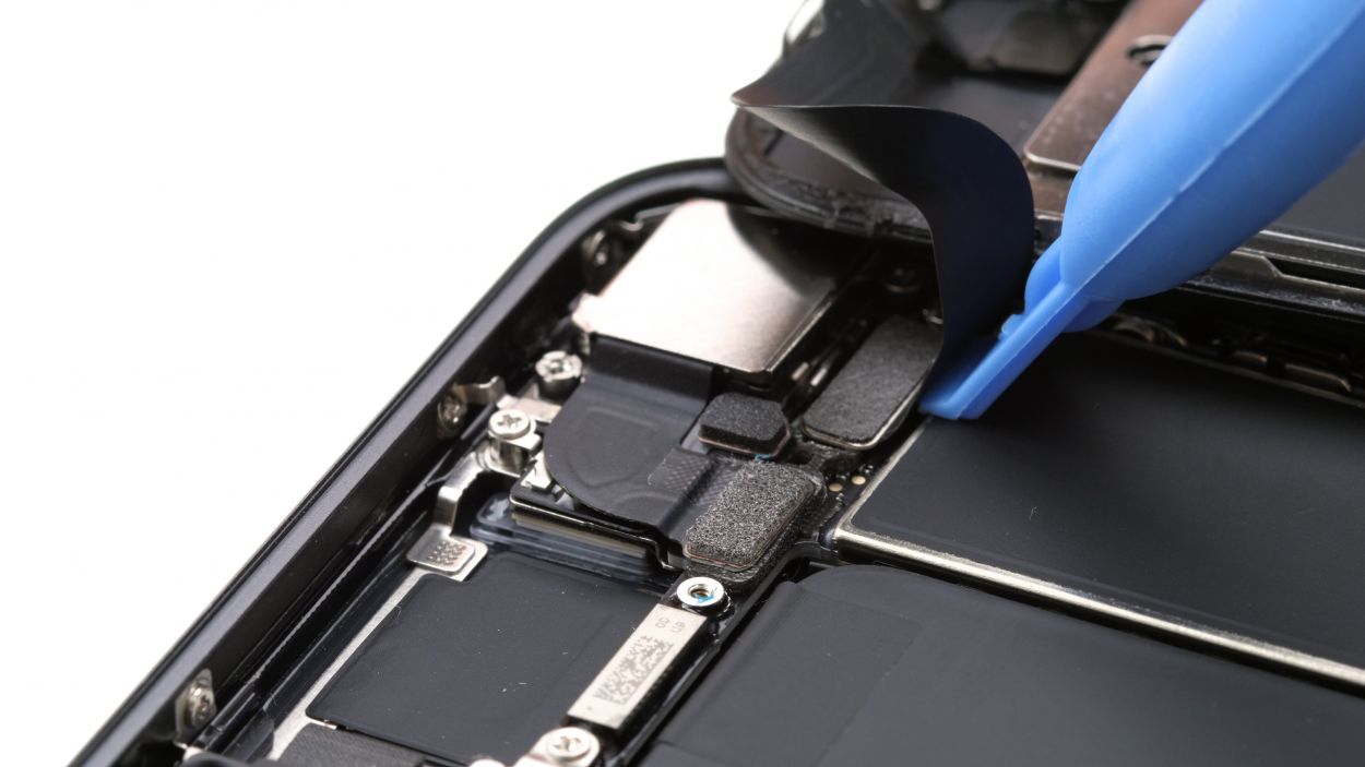
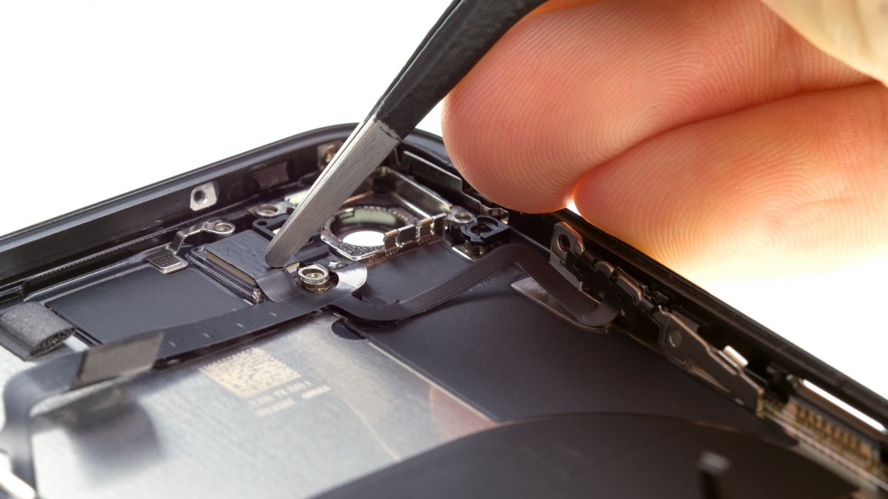
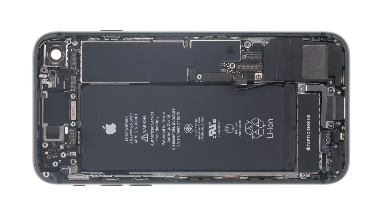
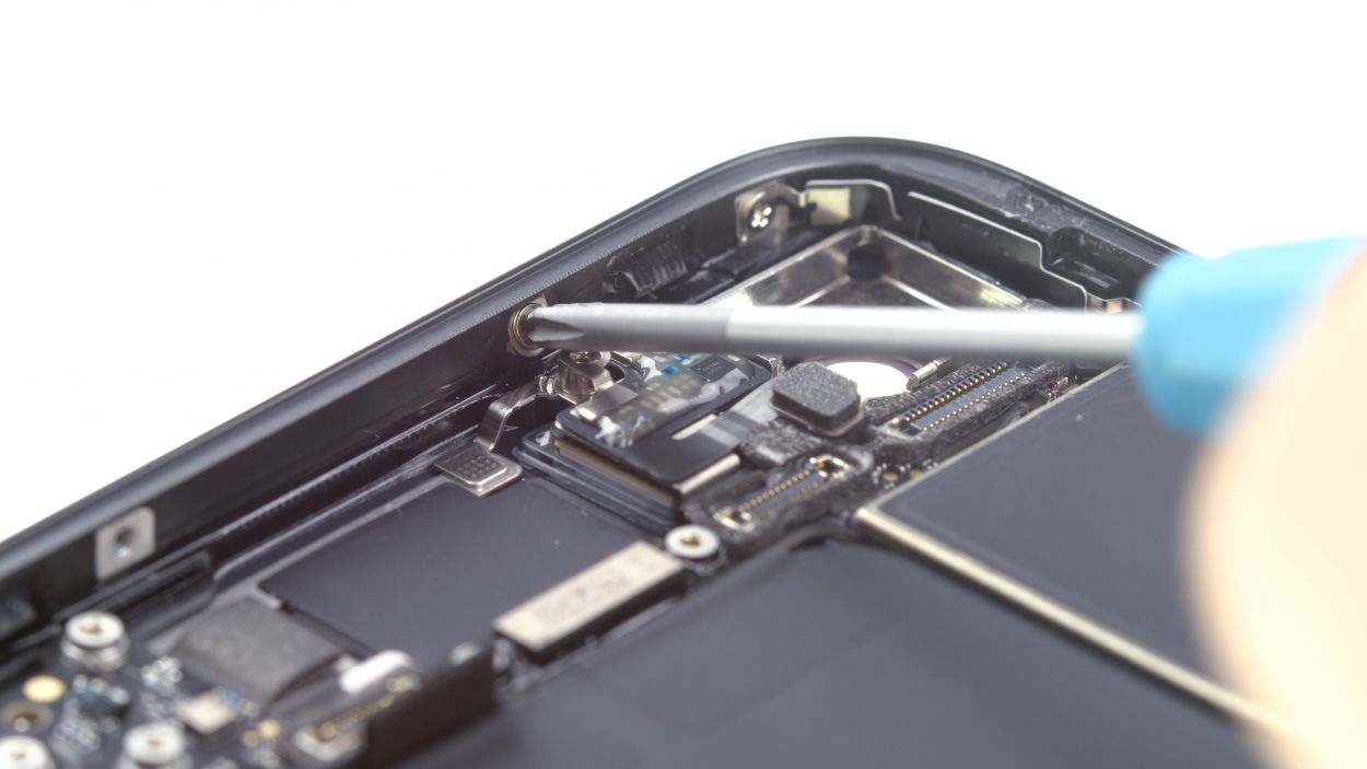
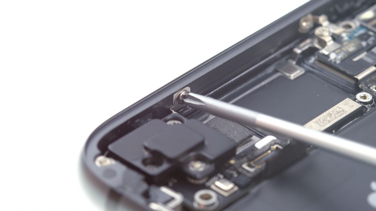
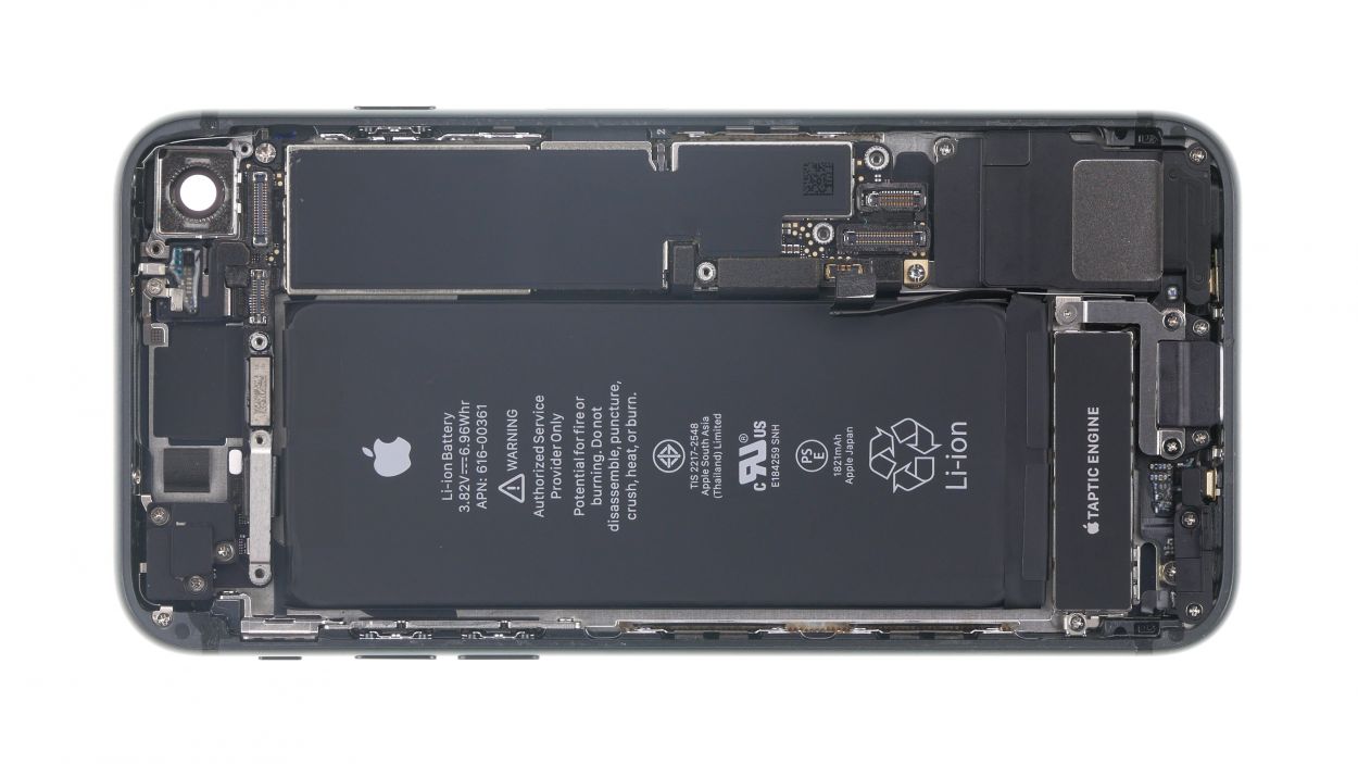
Step 9

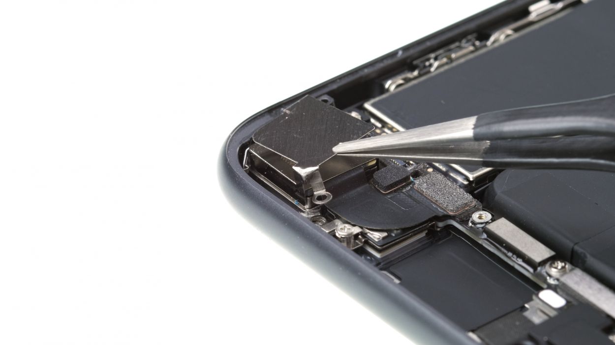
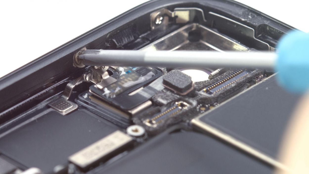
1 × 2.9 mm Phillips
1 × 3.0 mm Standoff
For those tricky stand-off screws, you can grab a specialized screwdriver, but don’t fret! A regular narrow slotted screwdriver will do the trick just fine. You’ve got this!
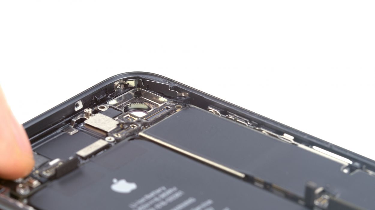
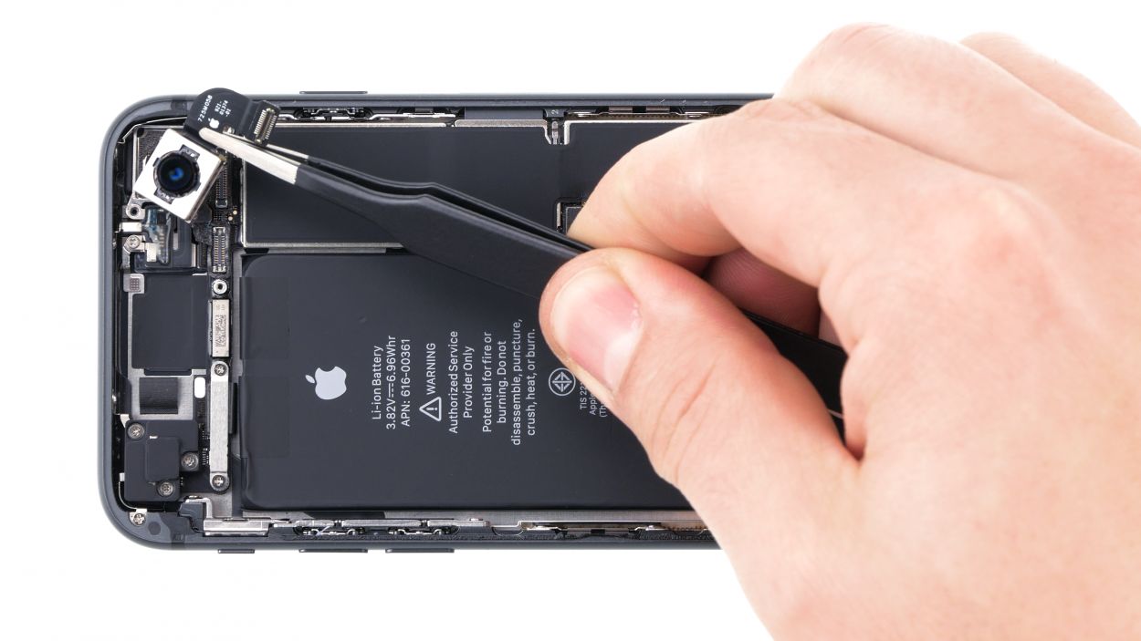
– Loosen those screws and pop off the cover plate of the iSight camera. You’re doing awesome!
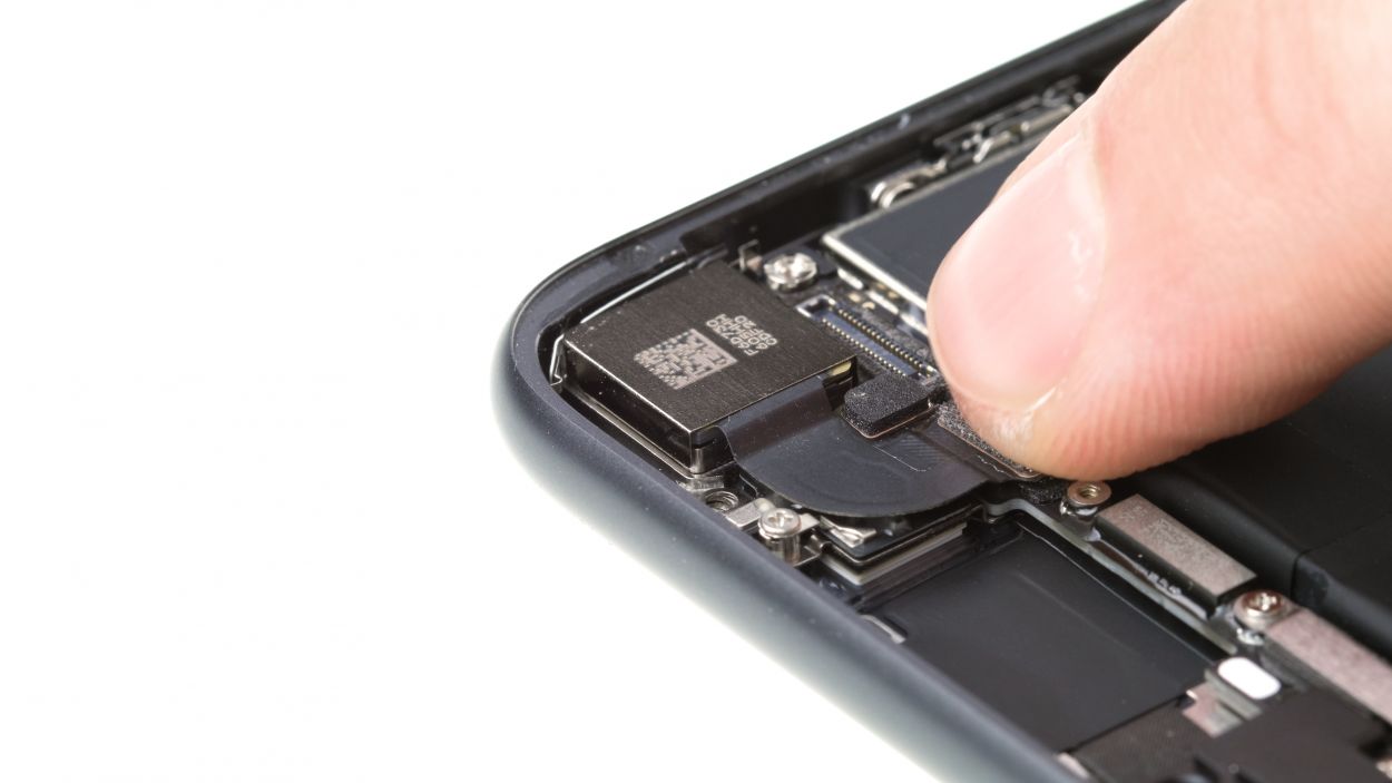
Step 10
1 × 1.1 mm Phillips
1 × 2.7 mm Phillips
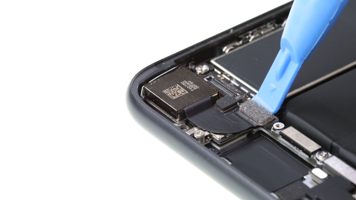
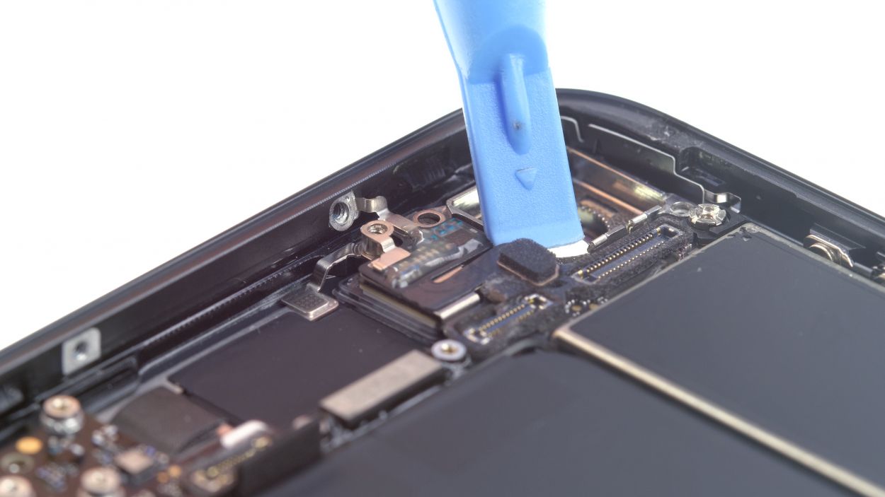
– First, let’s get those pesky screws out of the way! Unscrew the screws holding the bracket plate in place.
– Now, gently lift that bracket plate out of your device like you’re unveiling a surprise!
– Finally, it’s time to disconnect the connector from the logic board. Use a plastic spudger and carefully lever it off. You’ve got this!
Step 11
2 × 1.2 mm Philliips
2 × 1.0 mm Philliips
1 × 2.5 mm Phillips
1 × 1.4 mm Phillips
One of the screws is playfully nestled into the side of the back cover, just waiting for you to give it some attention!
– First, let’s get those screws of the plastic bracket all loosened up so they can take a little break!
Step 12
1 × 1.3 mm Phillips
1 × 1.2 mm Phillips
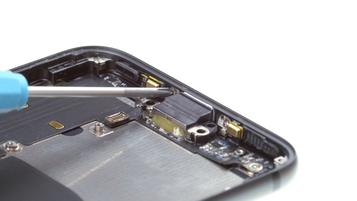
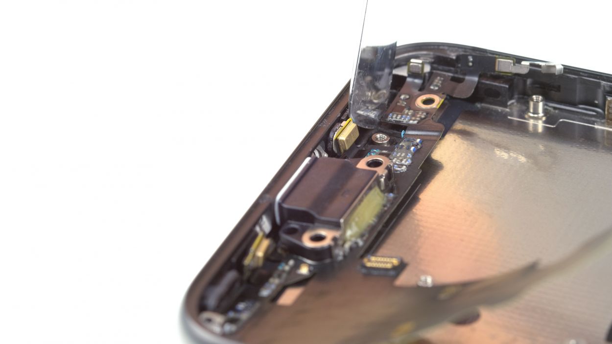
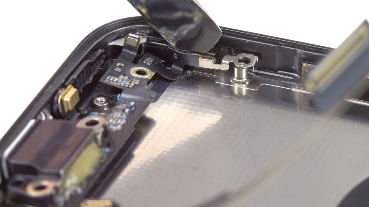
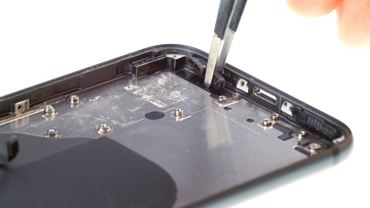
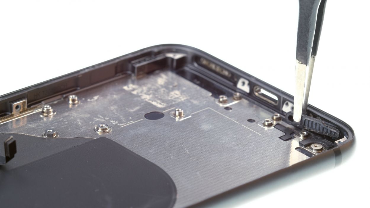
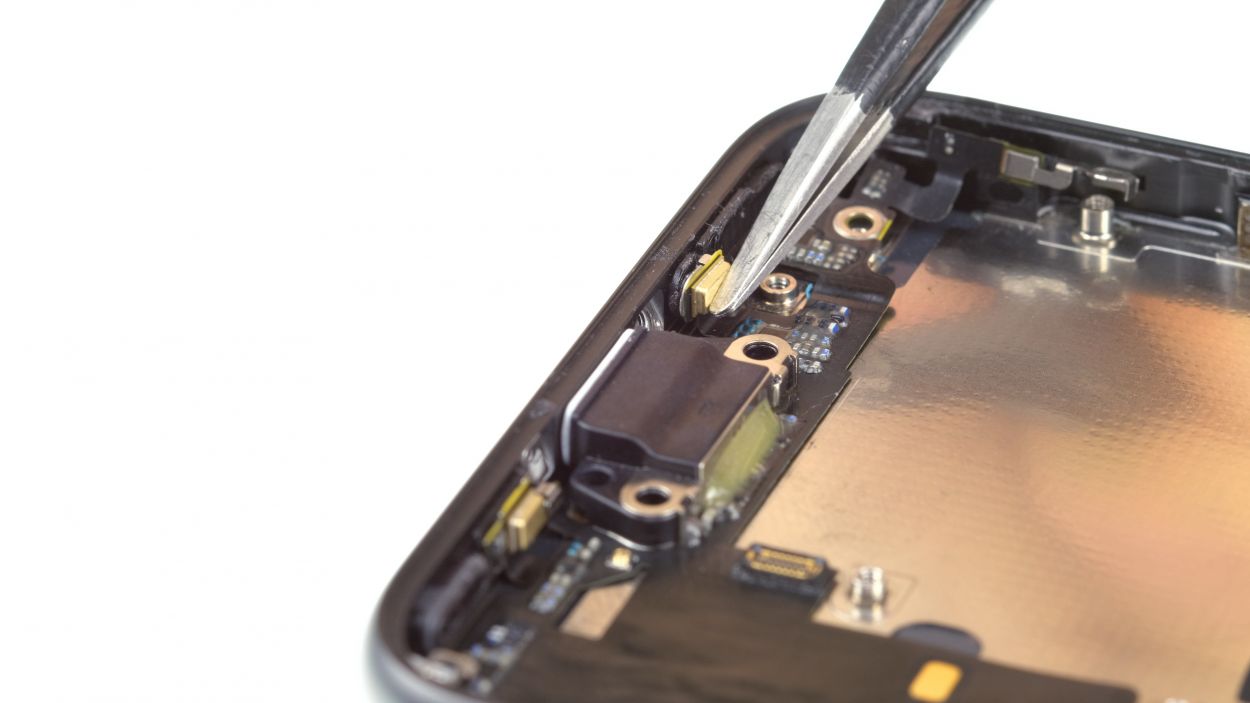
– First, let’s tackle those Phillips screws holding the antenna in place. Give them a twist and send them packing!
– Next, gently disconnect the connector from the board. You’re doing great!
– If the antenna is feeling a bit stubborn, warm it up with some hot air to loosen things up. Then, with a spatula in hand, carefully pry it off. You’ve got this!
Step 13
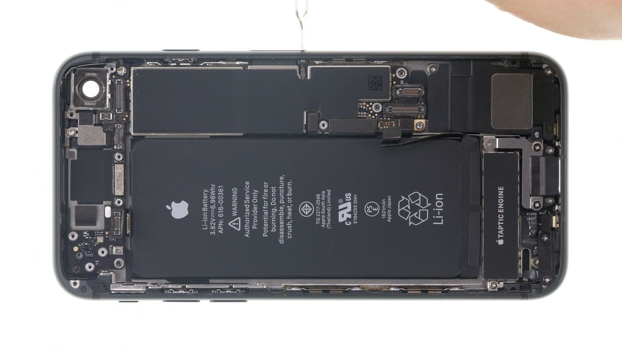
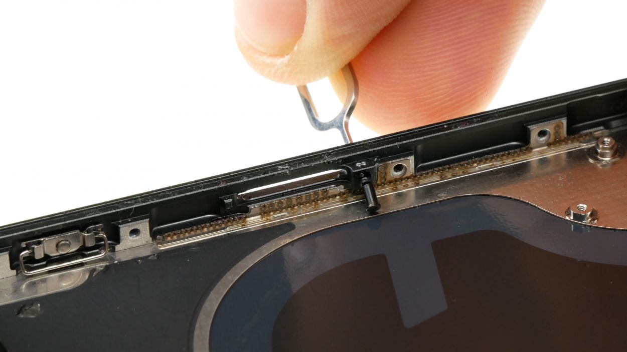
– Grab your trusty SIM tool or a paper clip and get ready to make some magic happen! Just press that tool into the little hole right next to the SIM card holder, and voilà! The SIM card holder will pop right out.
Tools Used
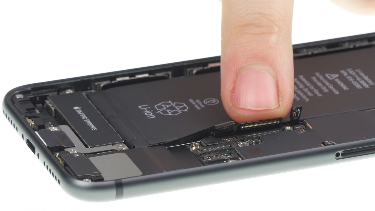
Step 14
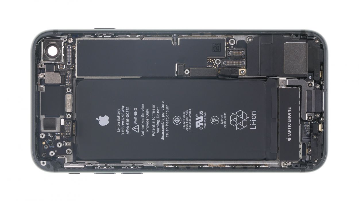
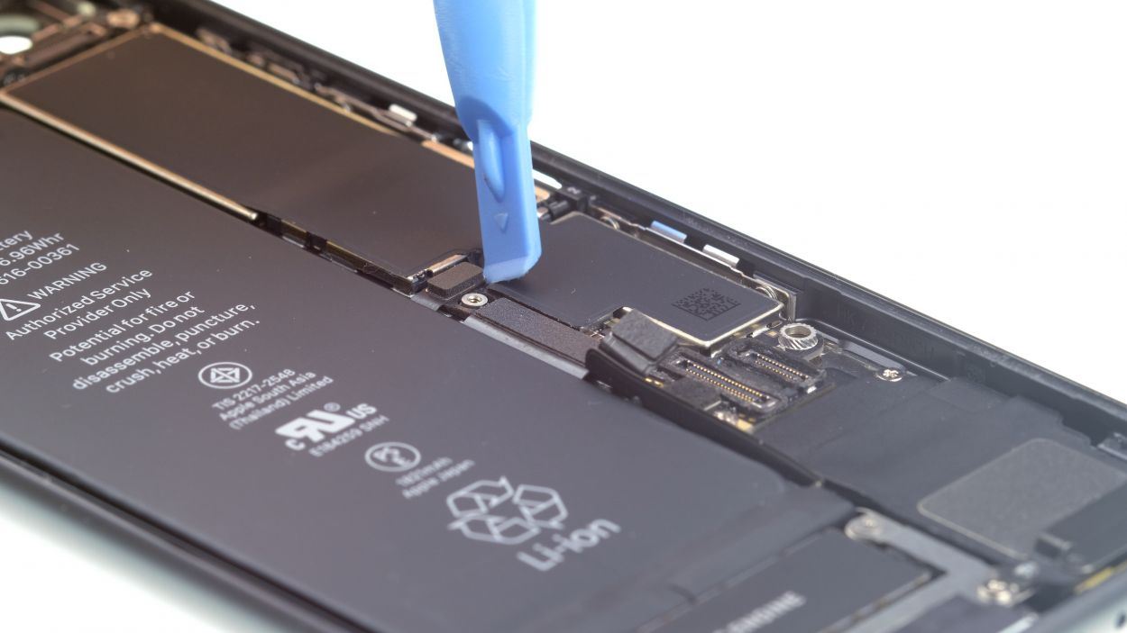
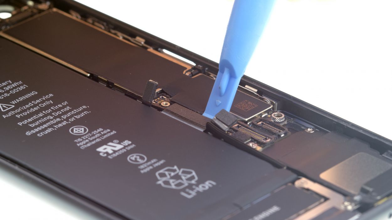

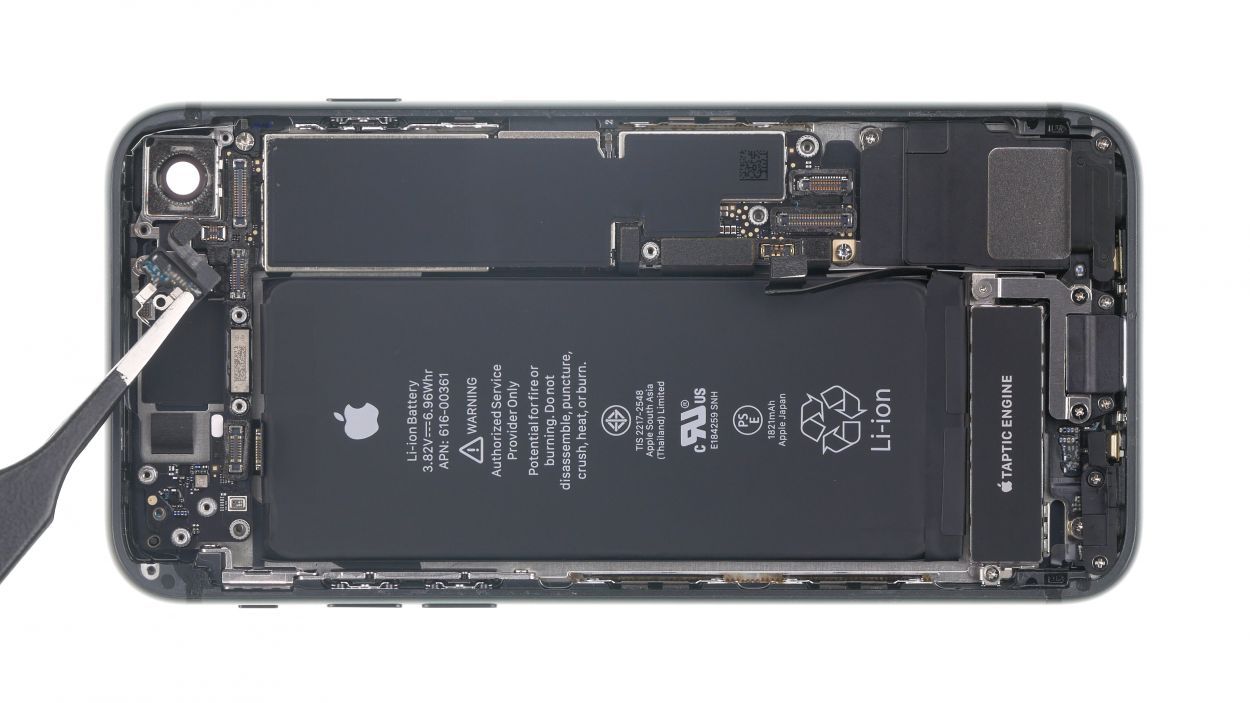
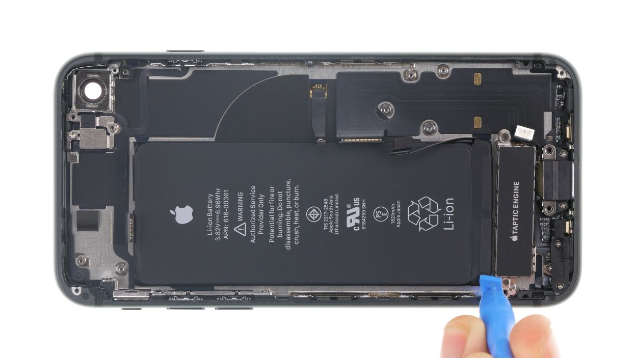
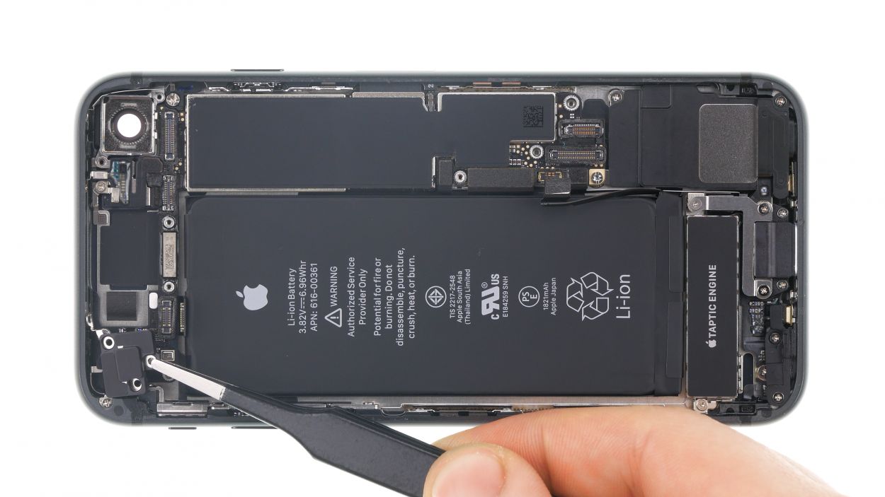
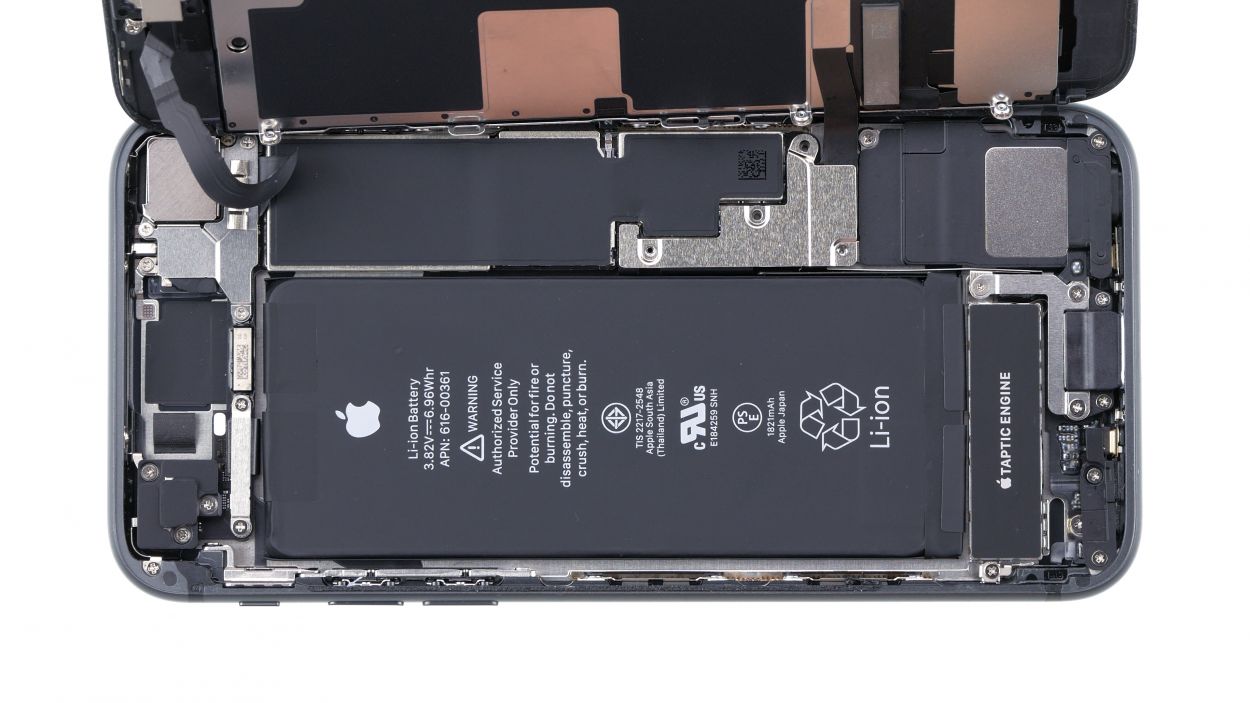
– Grab your trusty spudger and gently wiggle it to disconnect those three connectors on the battery side of the logic board. You’re doing a fantastic job!
Tools Used
Step 15
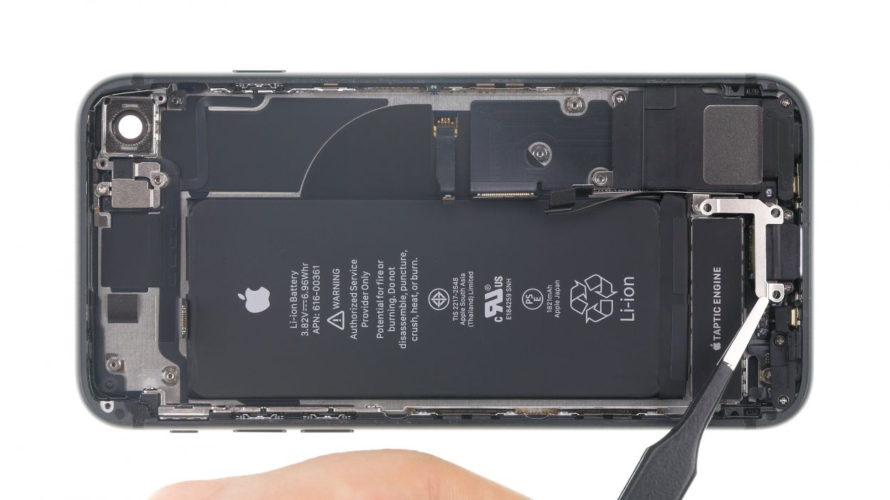
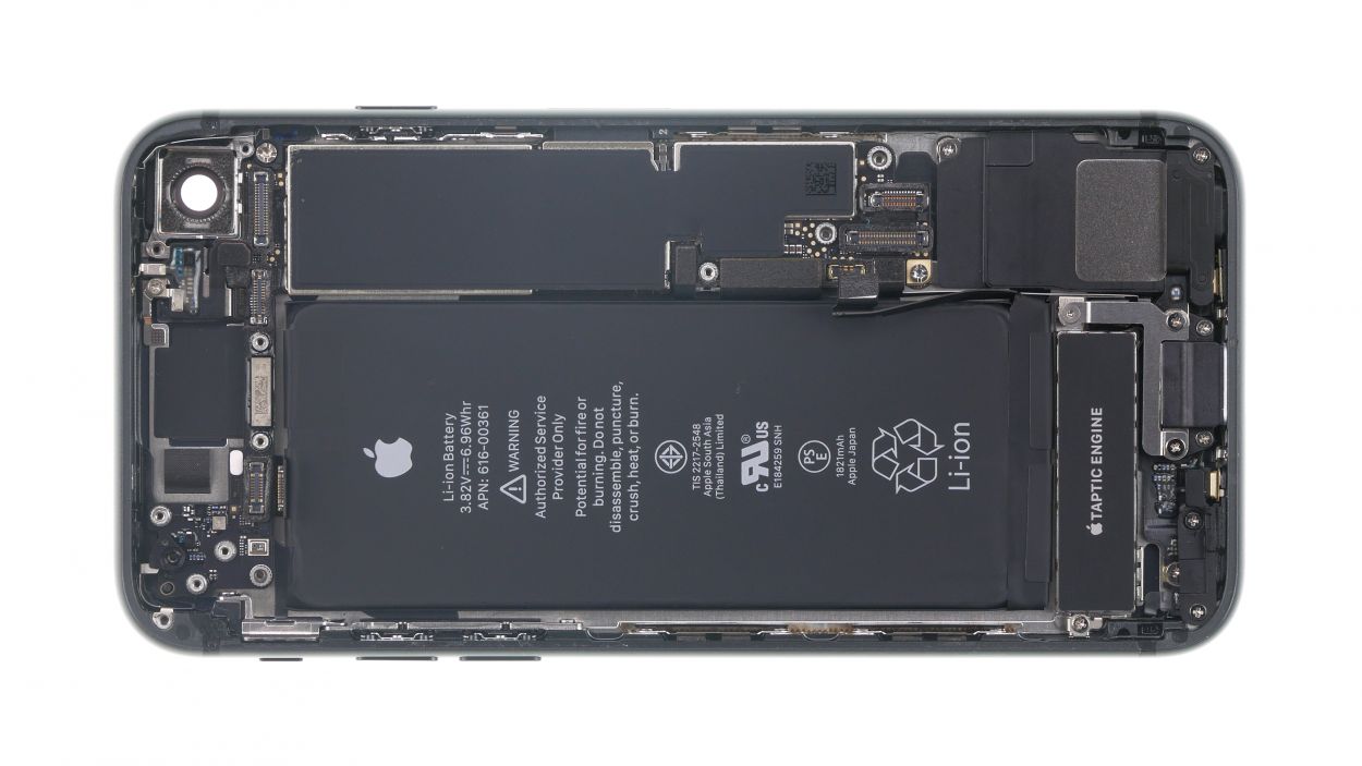
1 × 2.4 mm Standoff
1 × 2.1 mm Standoff
1 × 1.6 mm Phillips
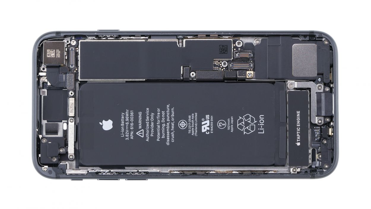
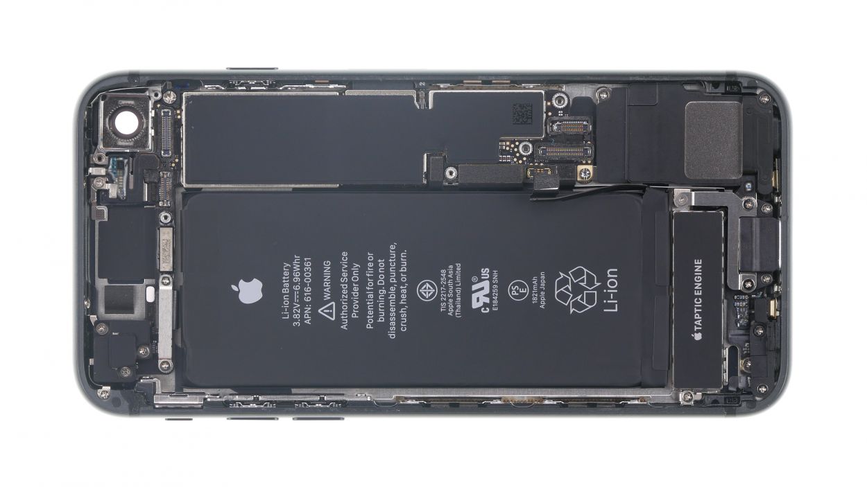
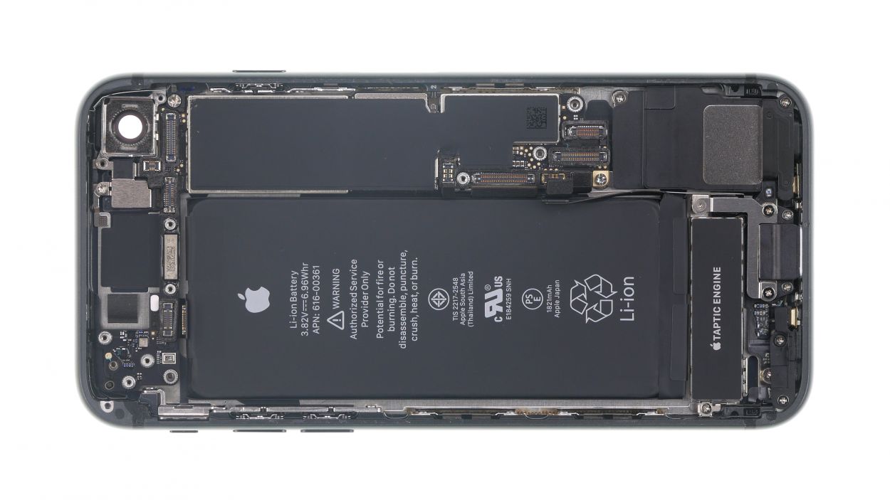
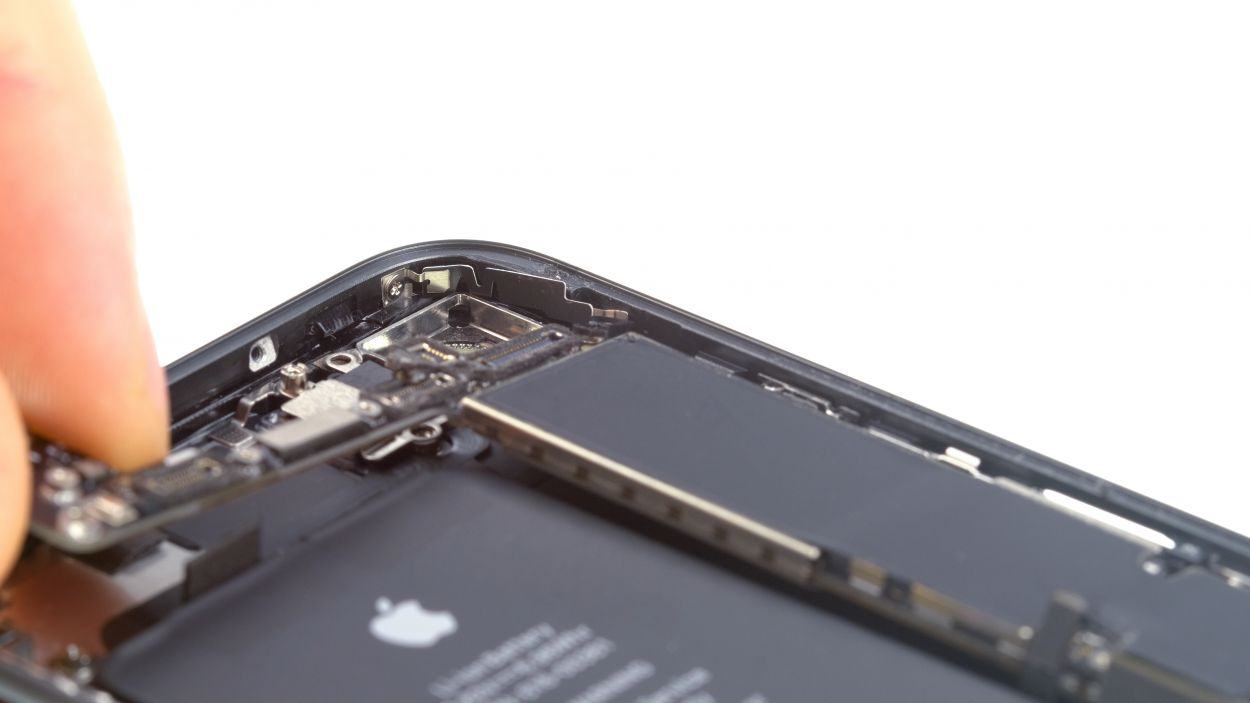
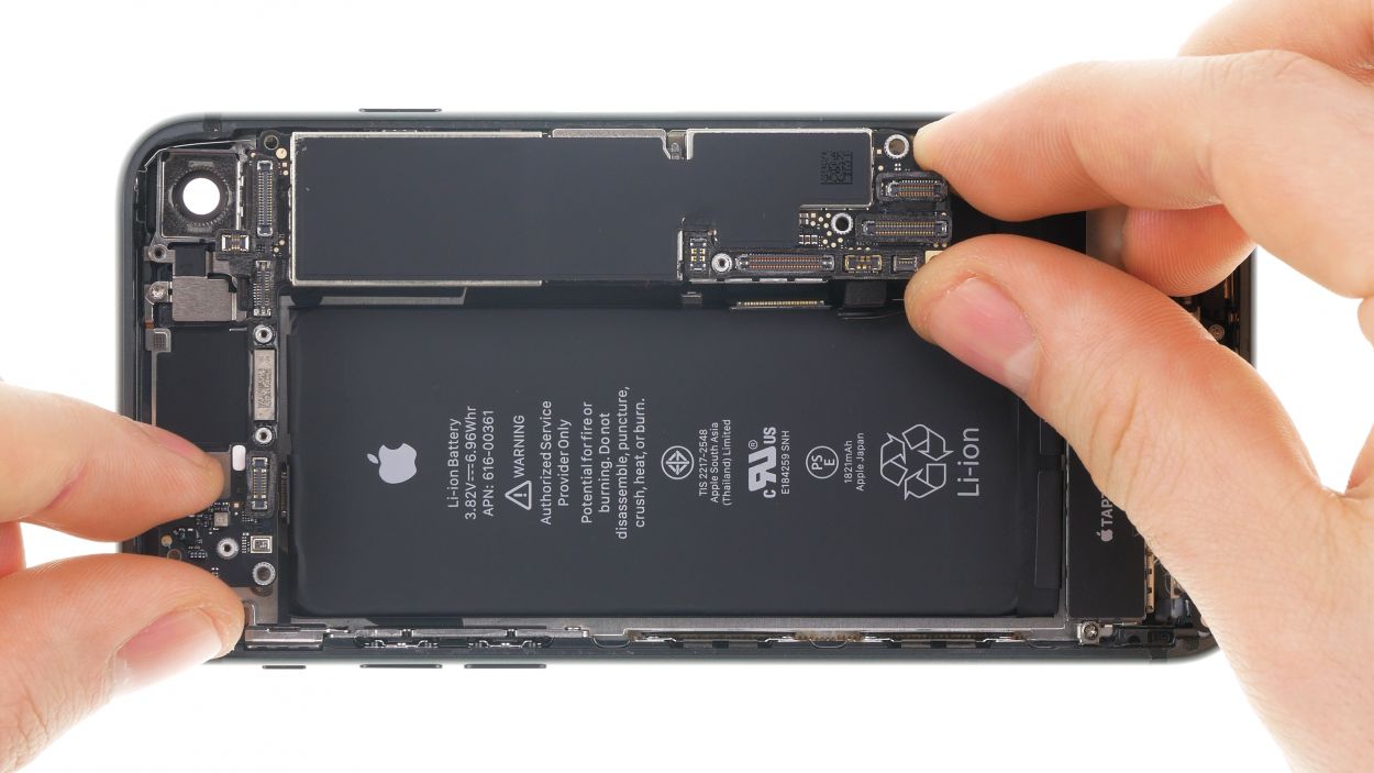
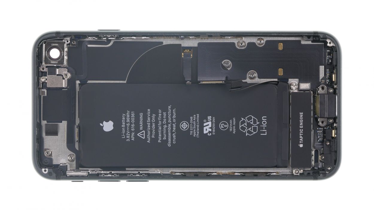
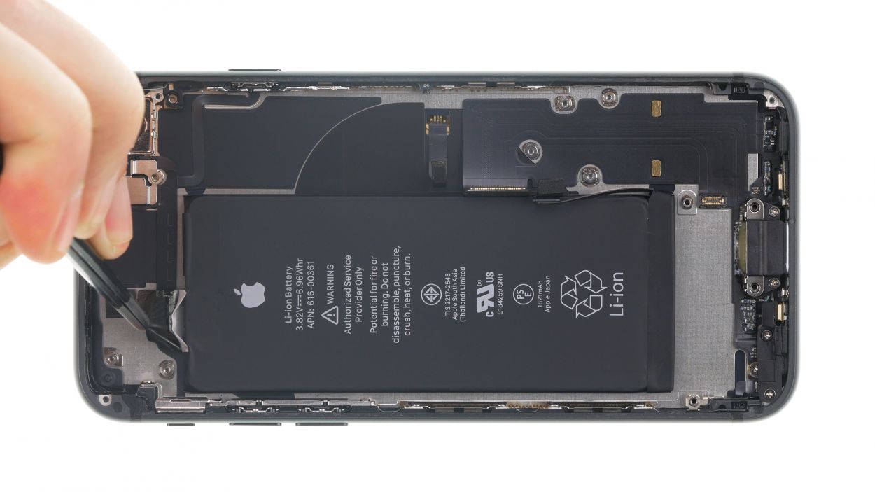
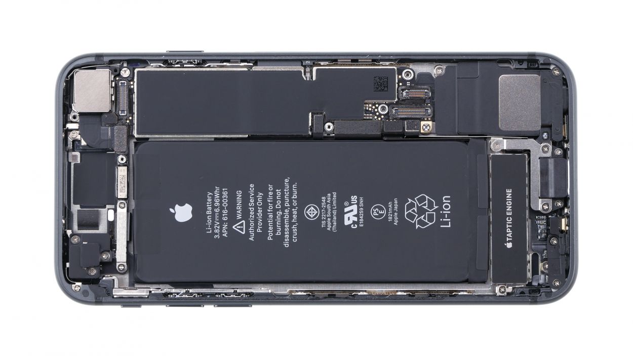
The Phillips screw is covered by a sticker (see photo).
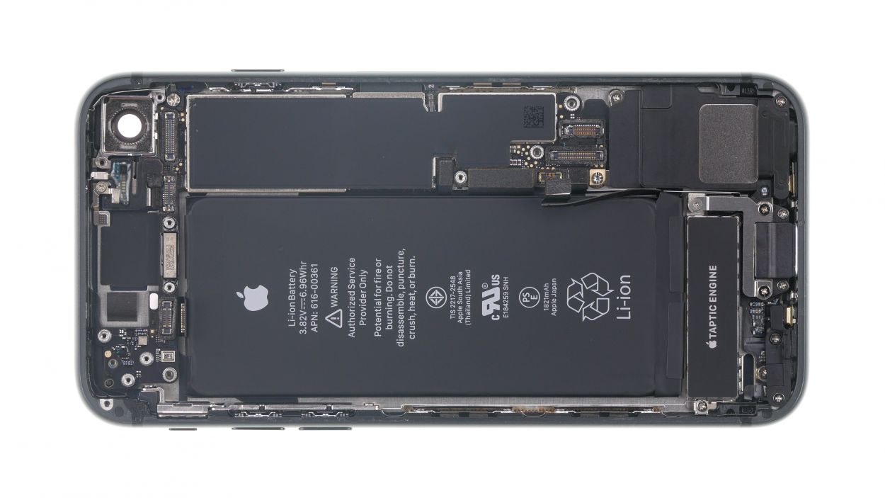
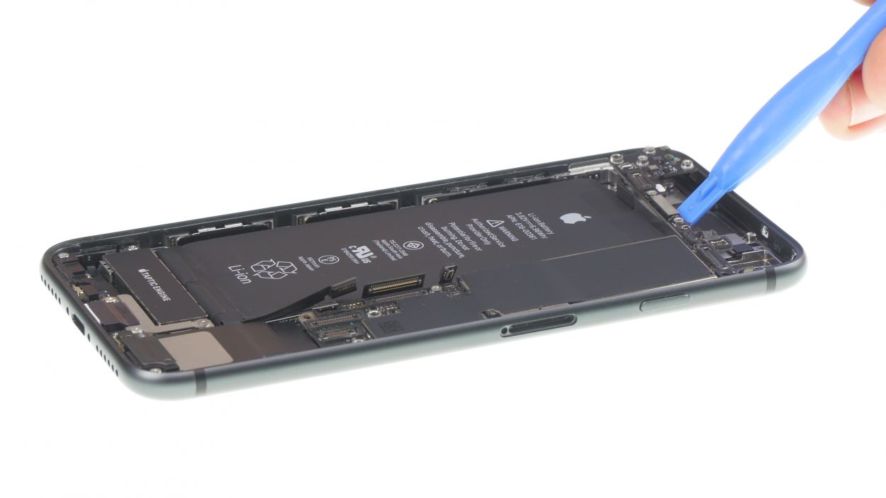
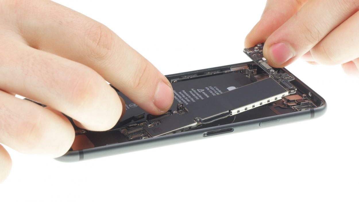
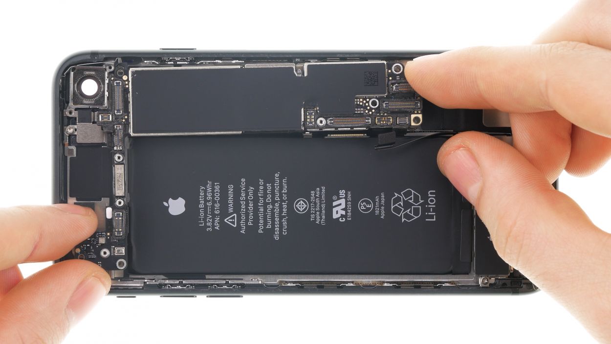
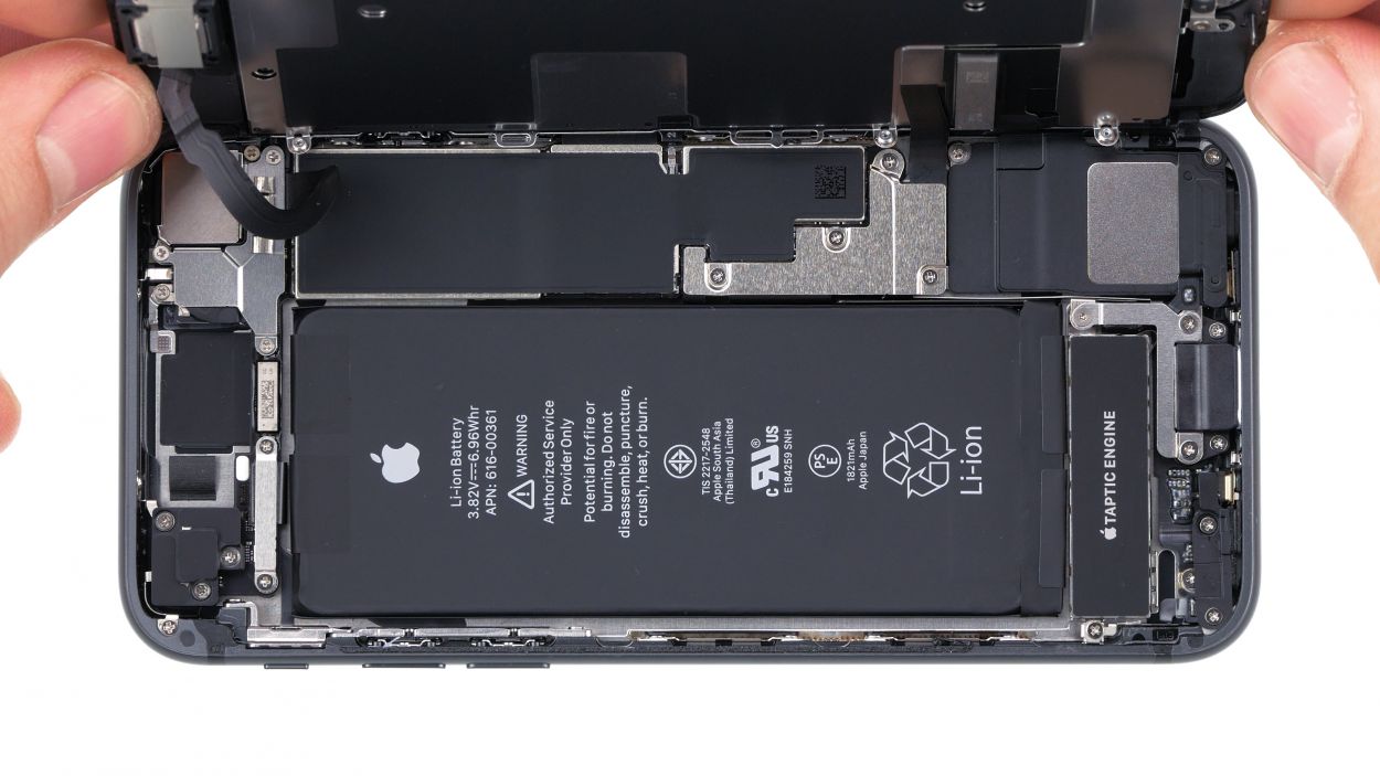
– Unscrew all screws that hold the logic board in place.
– Now you can carefully remove the logic board by hand. Next to the two holes for the iSight camera, there is a plastic holder for a screw.. This plastic holder is placed on top of the logicboard.
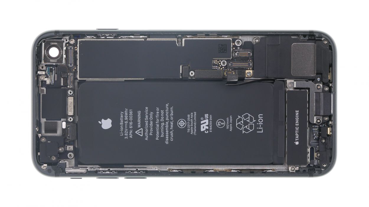
Step 16

1 × 1.2 mm Y-type
1 × 2.9 mm Phillips
1 × 2.5 mm Phillips
1 × 1.4 mm Phillips
1 × 2.1 mm Phillips
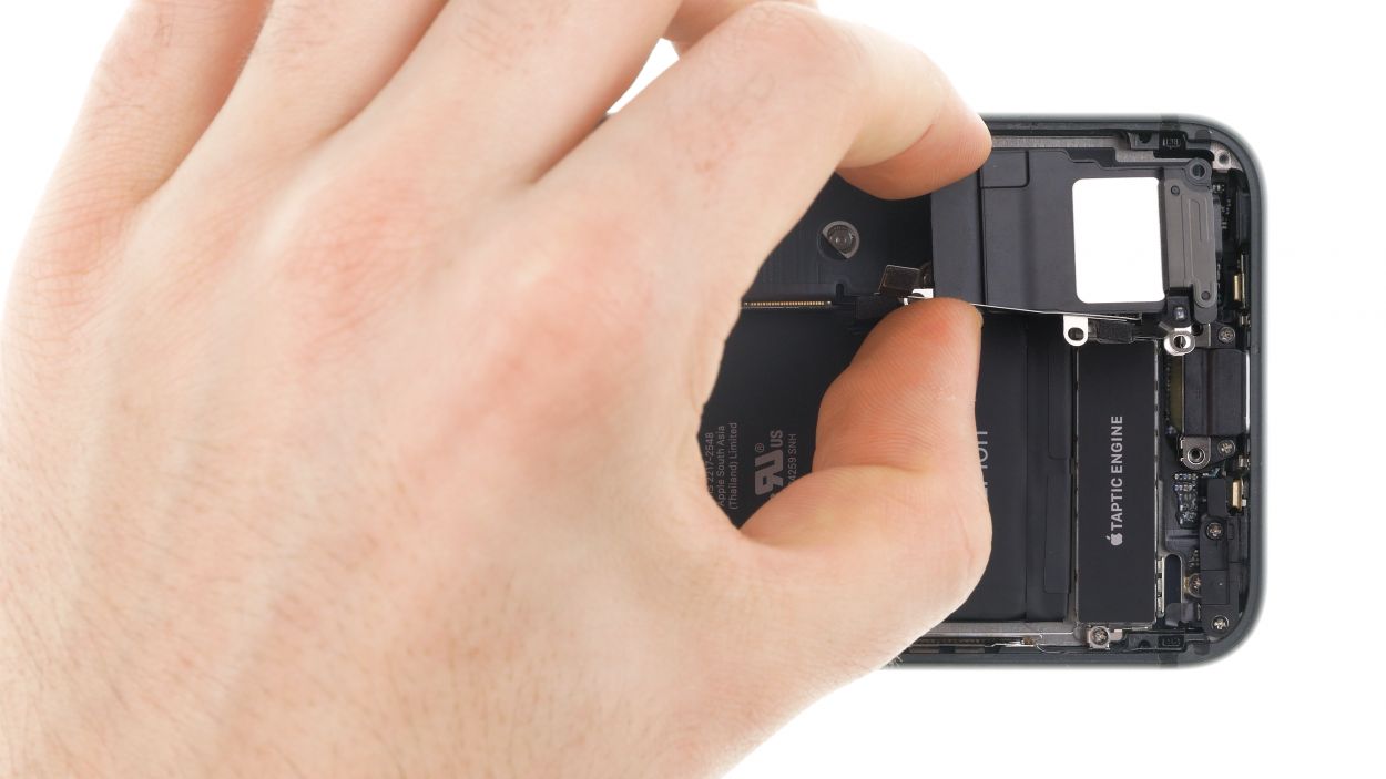
– First loosen the screws of the cover plate that lies over the connector of the flex cable and put it aside.
– Then disconnect the connector of the flex cable and lift it up.
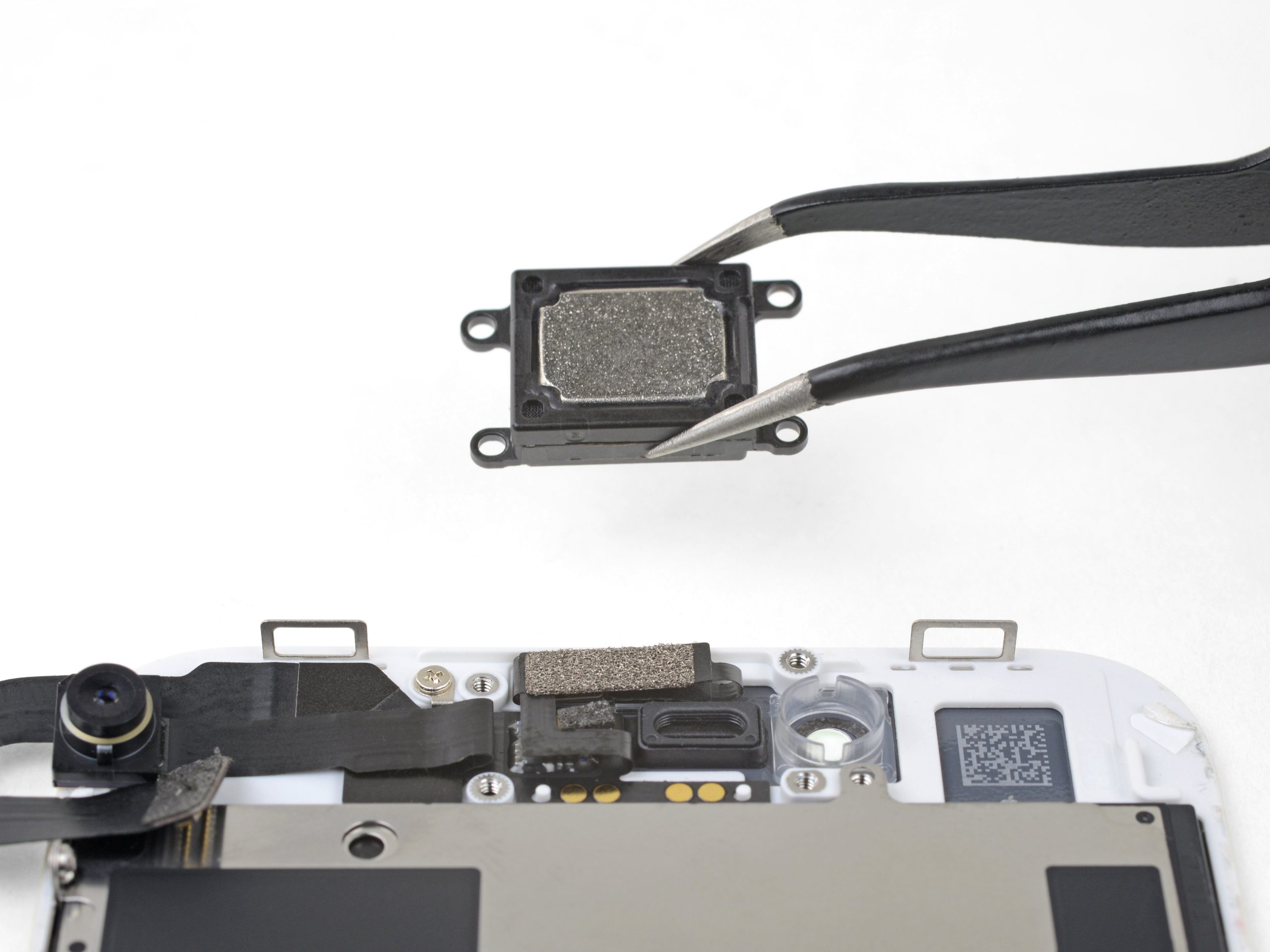
– Then loosen the screws of the speaker.
– You can now lift out the speaker and the flex cable.
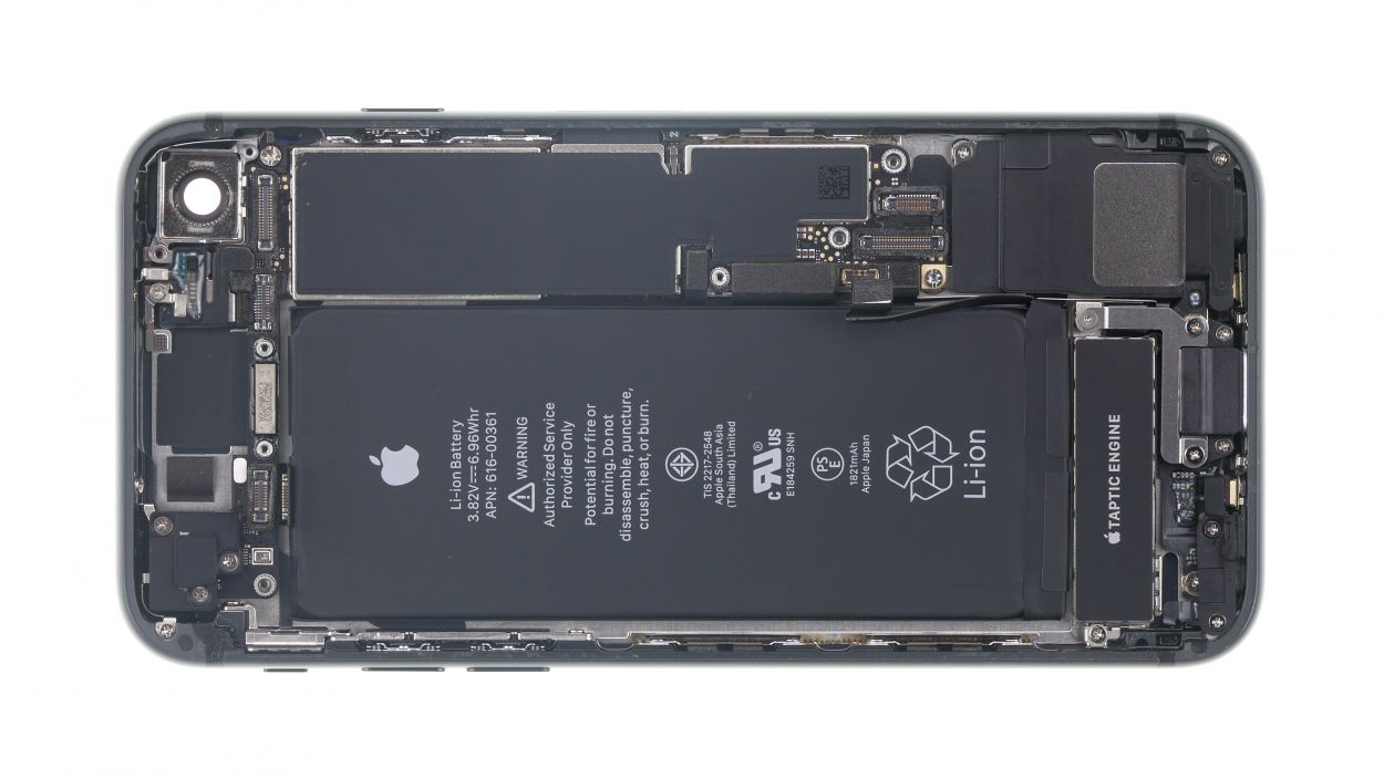
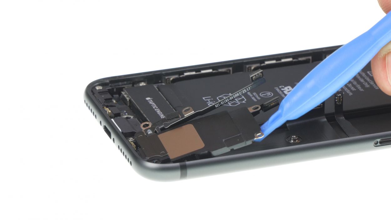
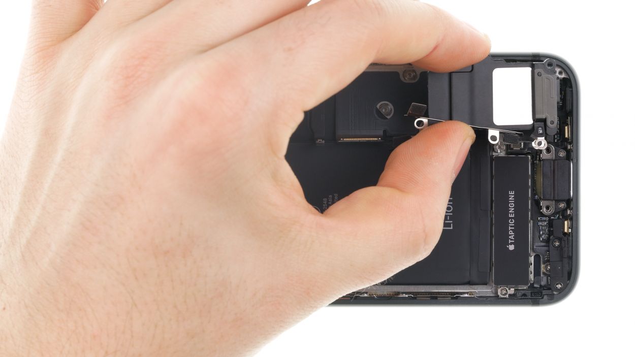
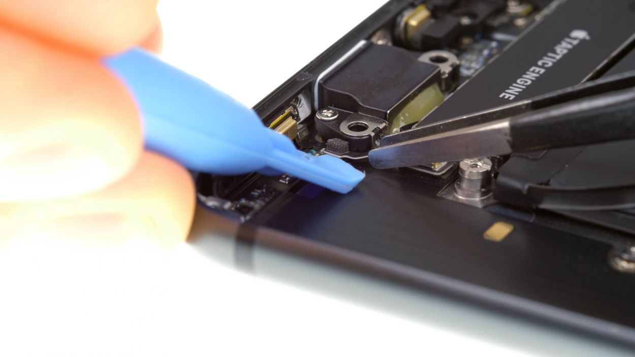
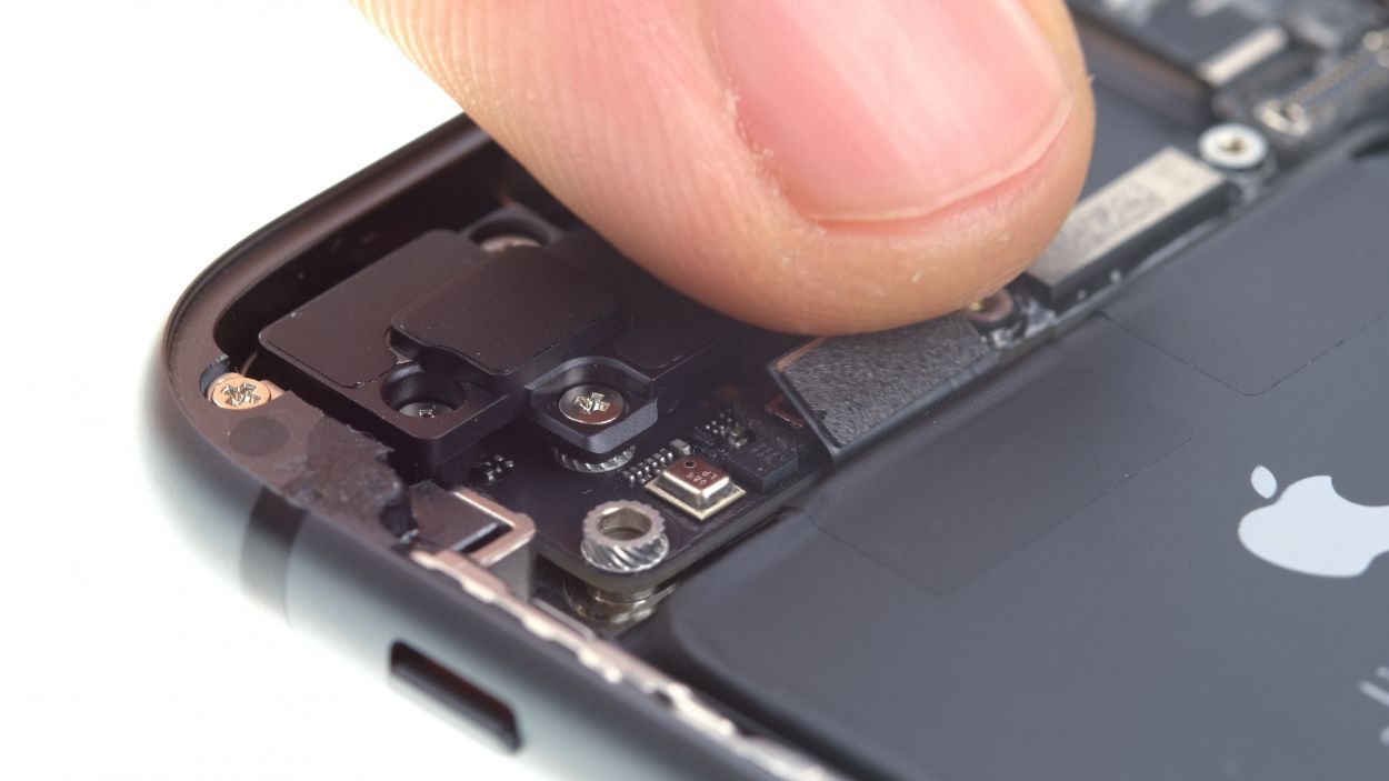
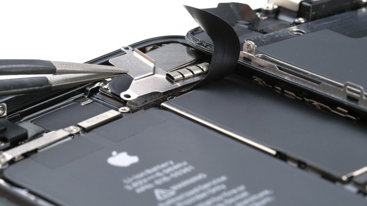
Step 17
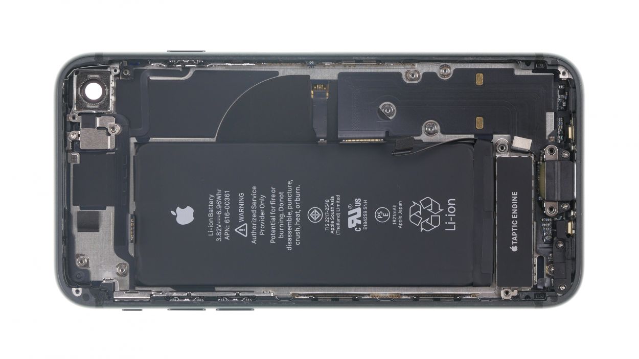
1 × 2.0 mm Standoff
1 × 2.0 mm Phillips
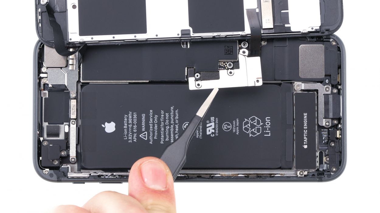
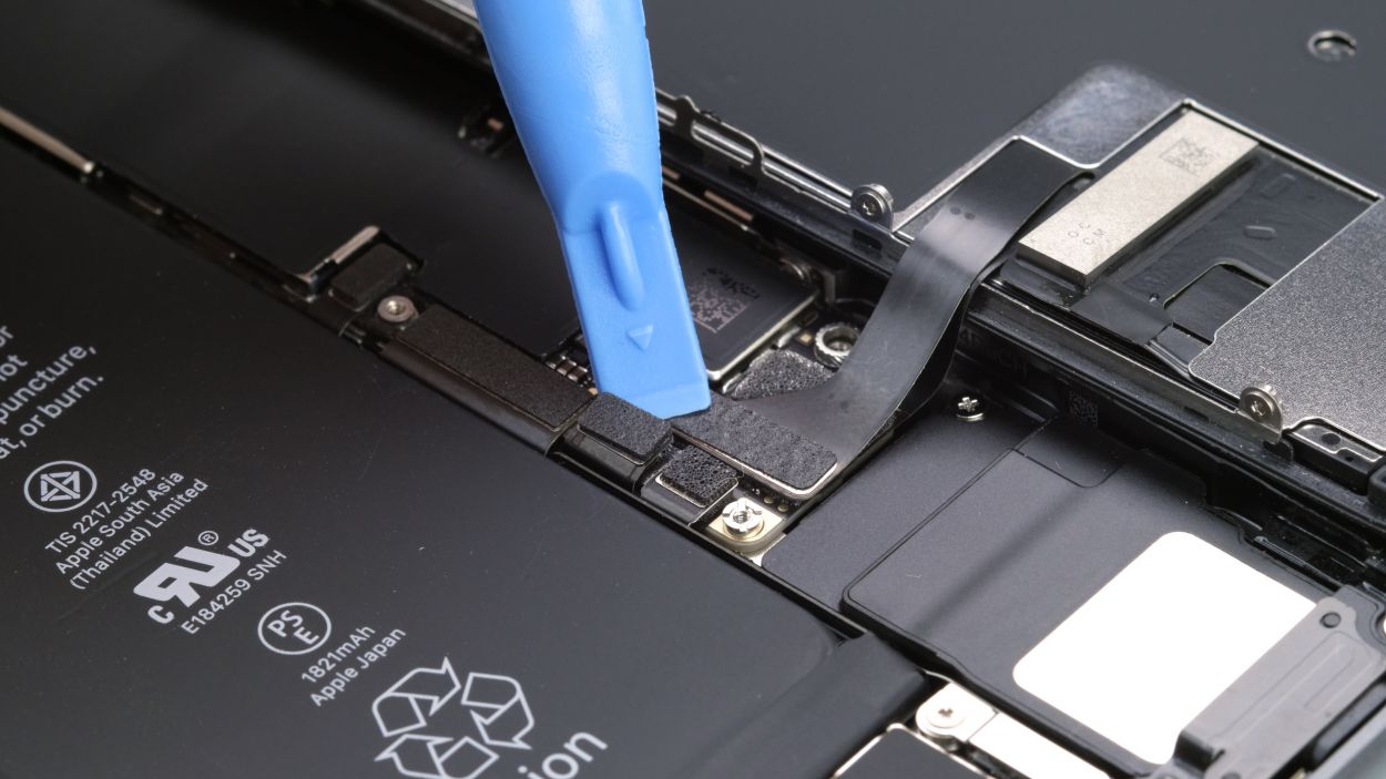
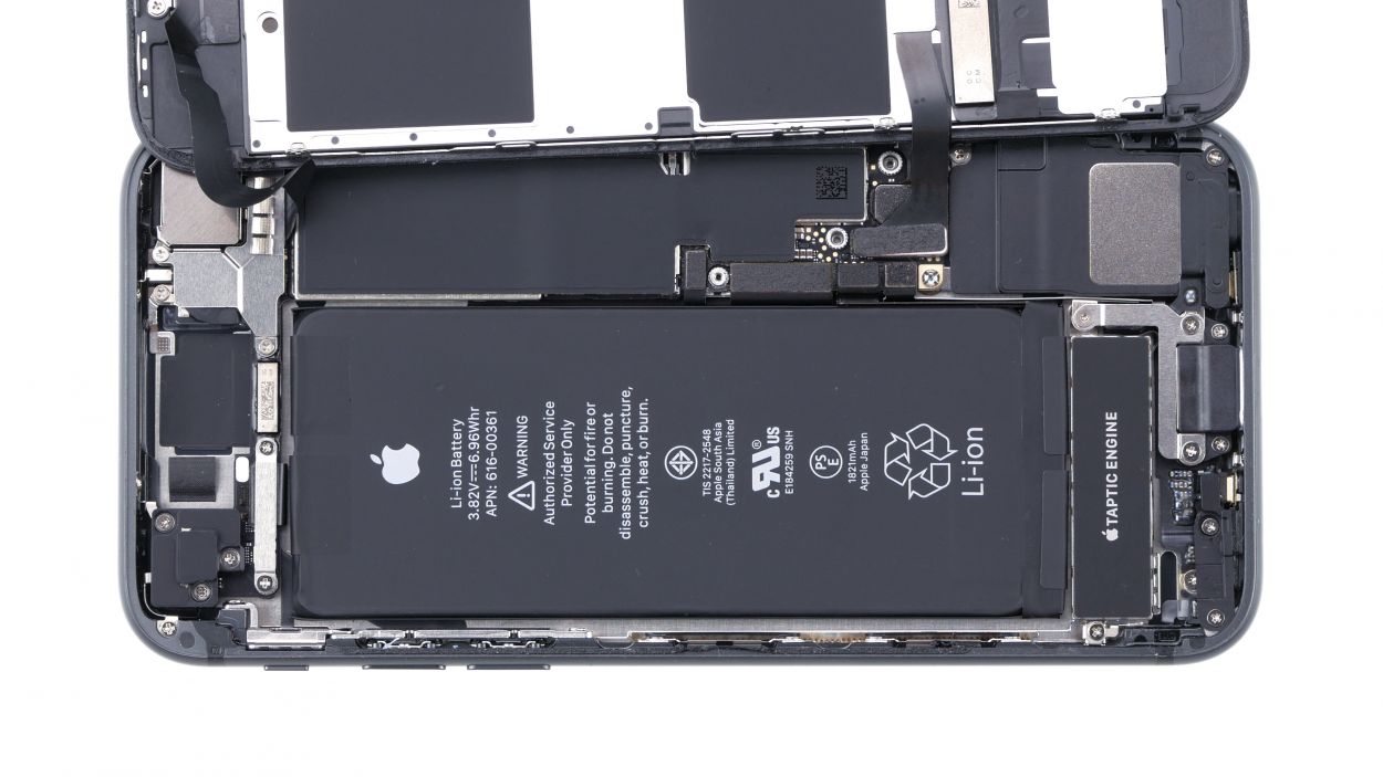
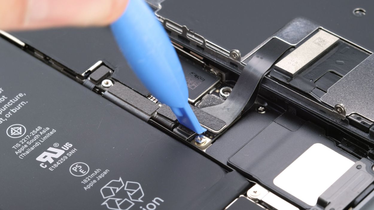
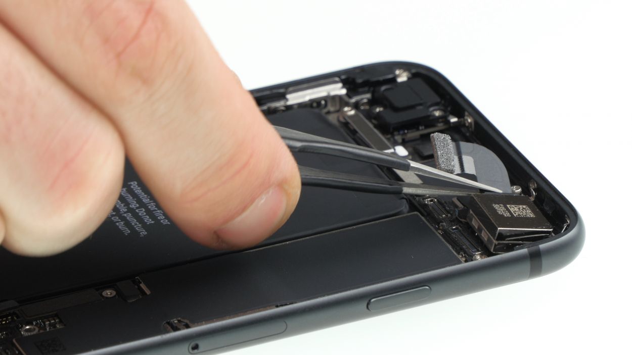
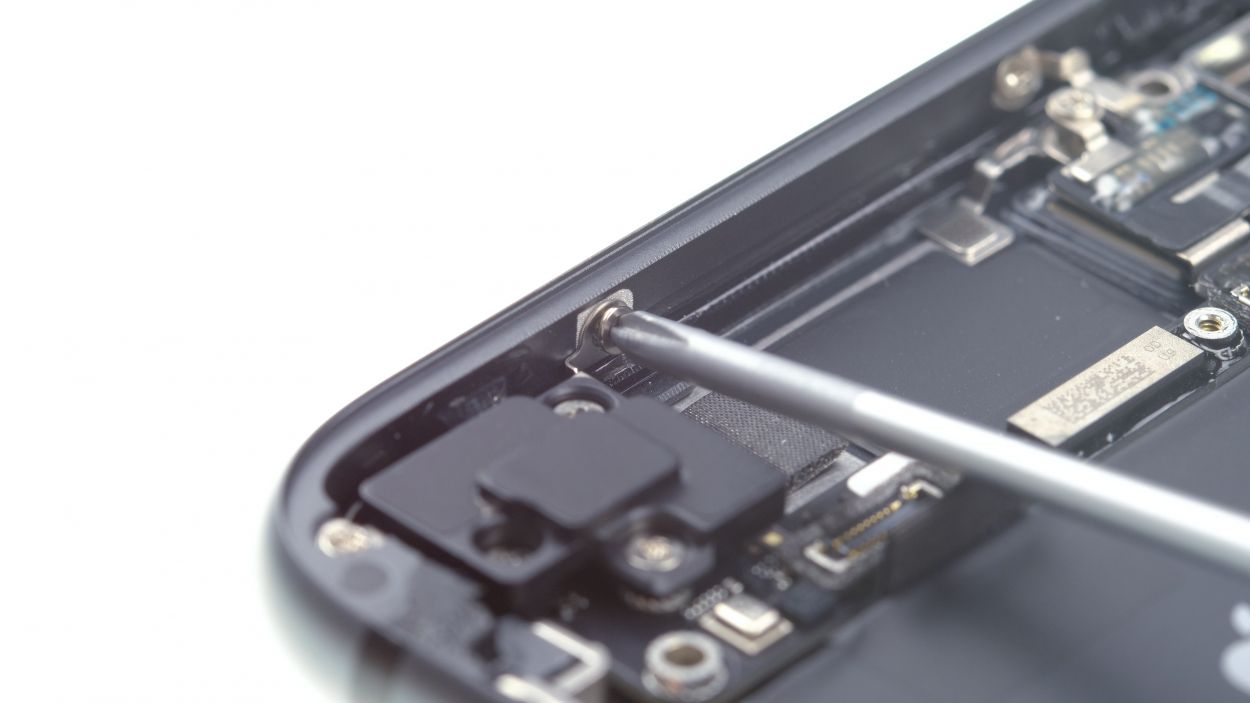
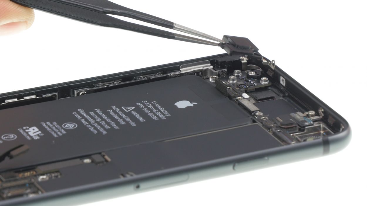
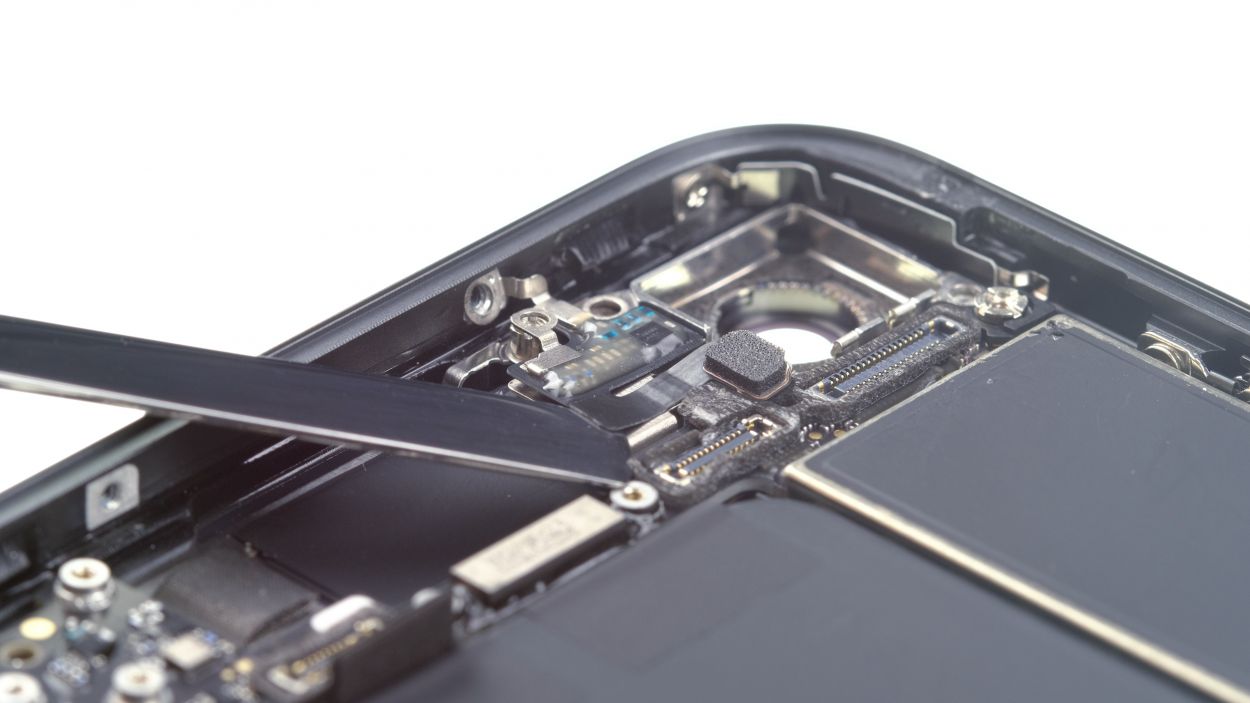
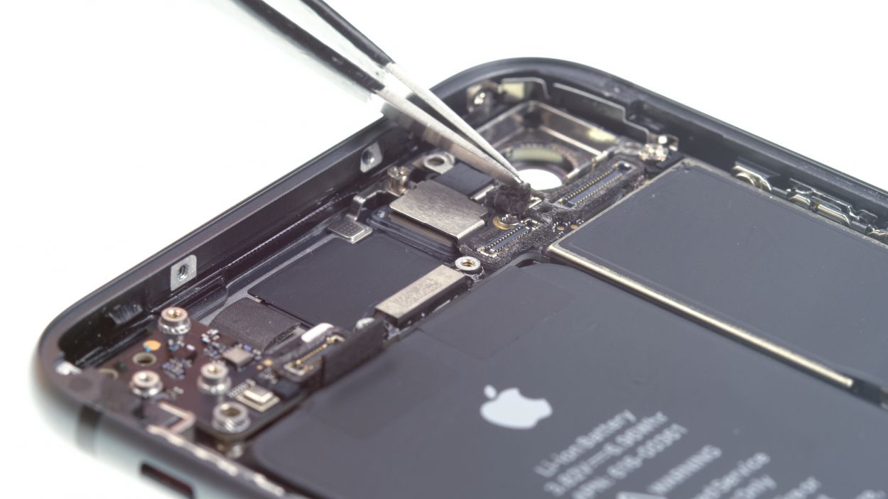
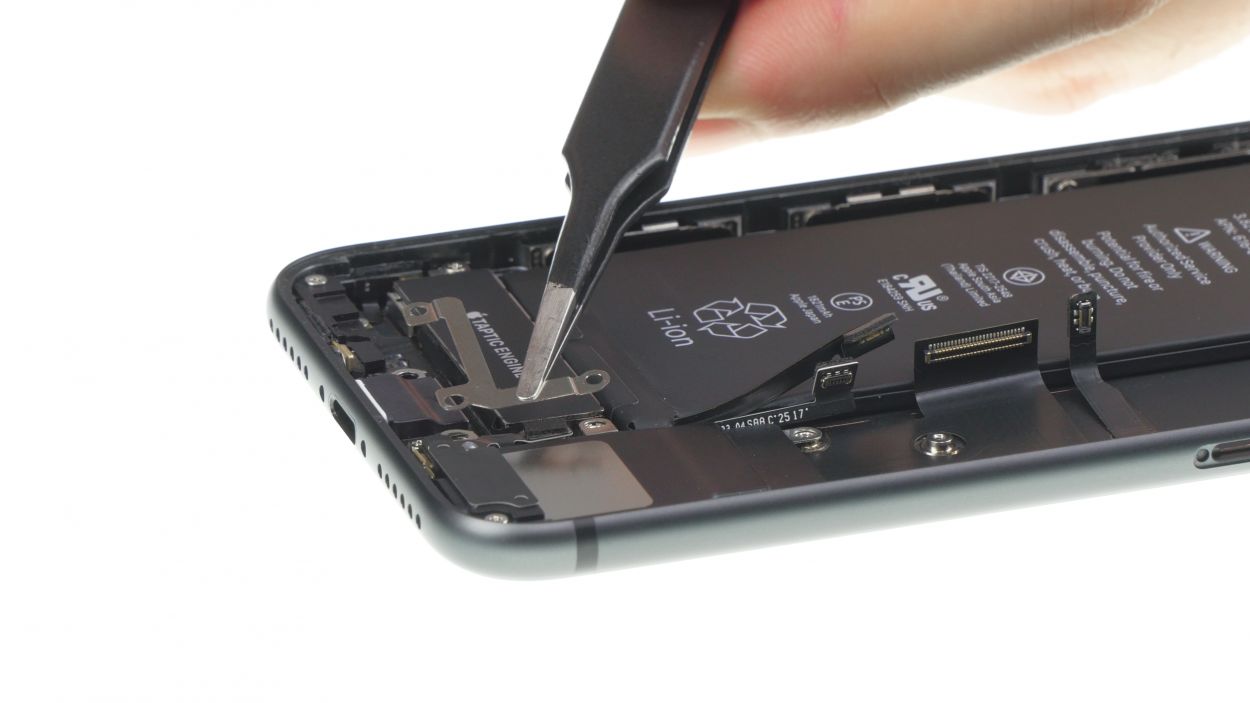
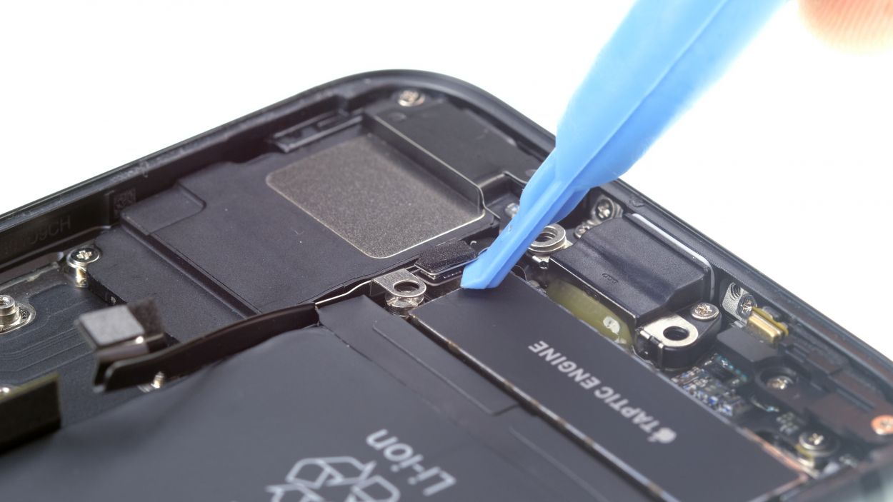
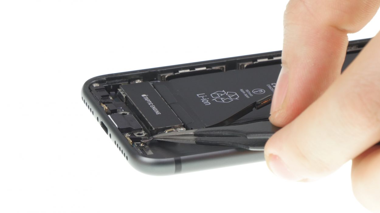
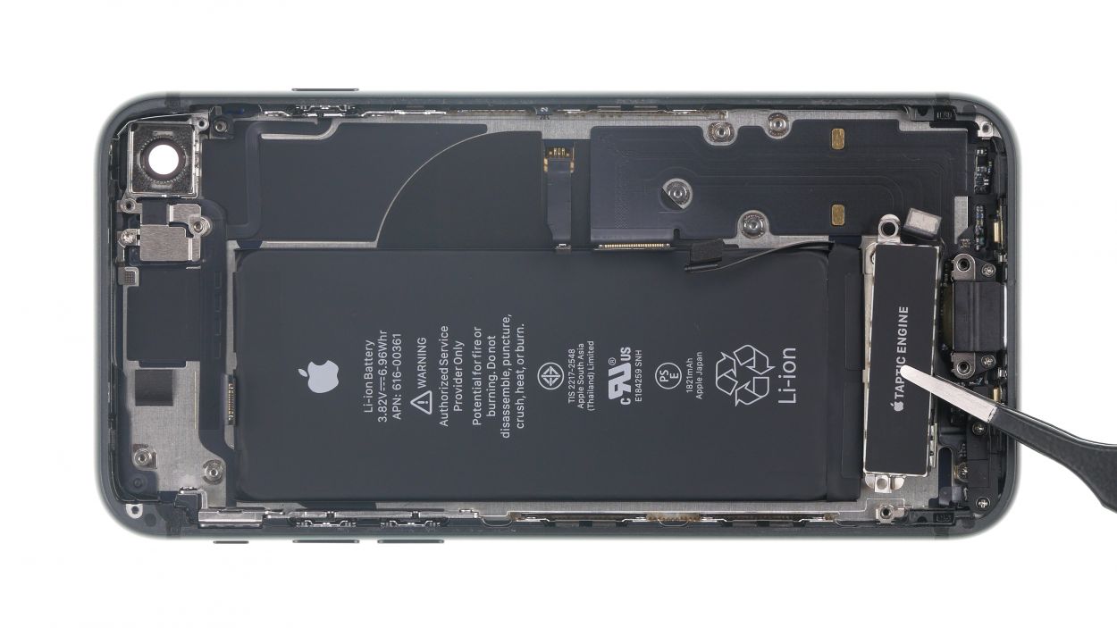
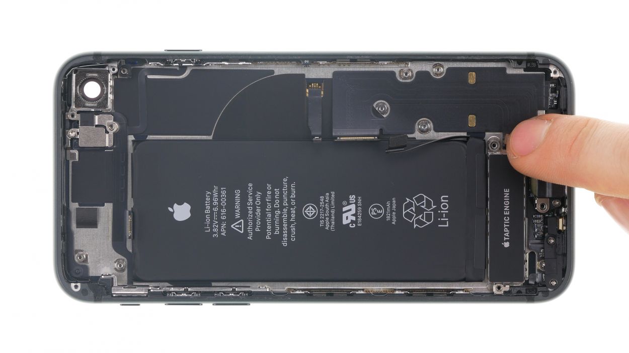
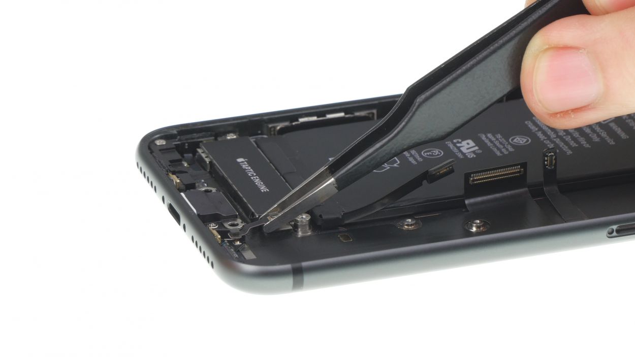
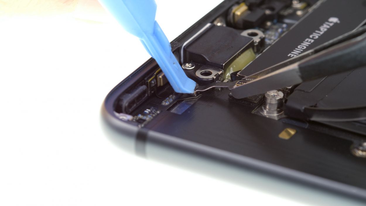
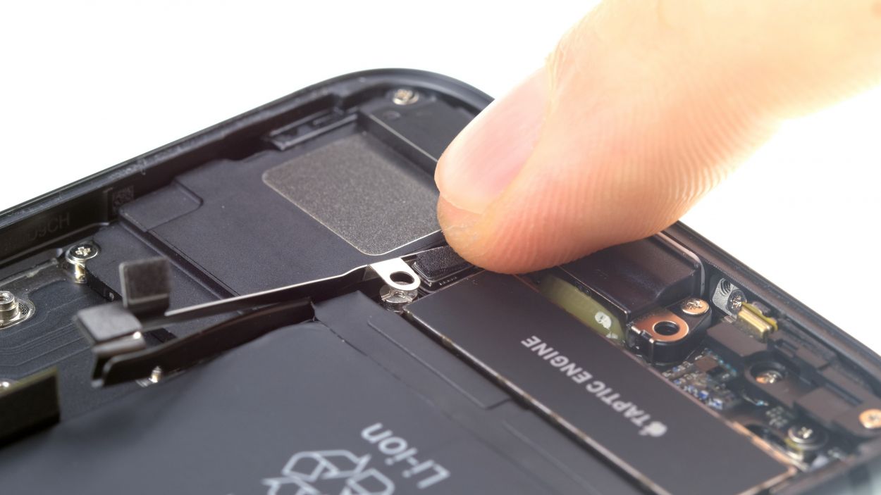
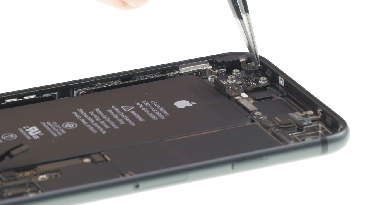
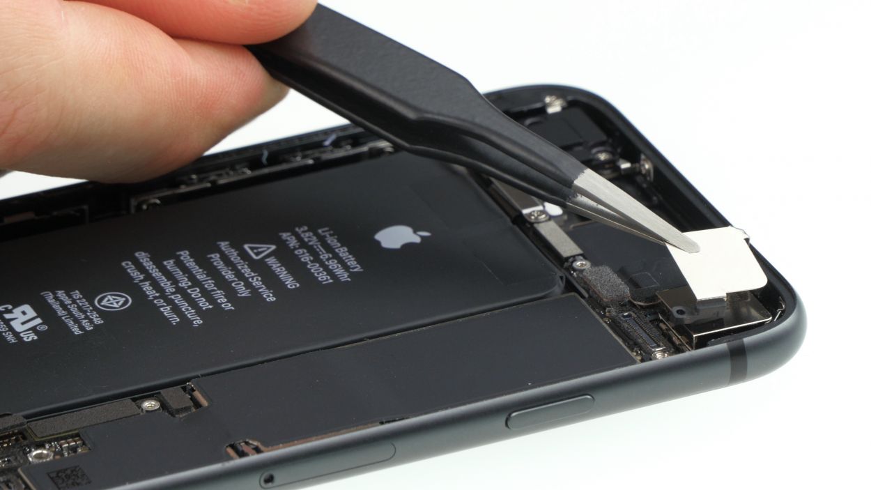
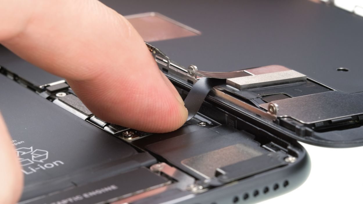
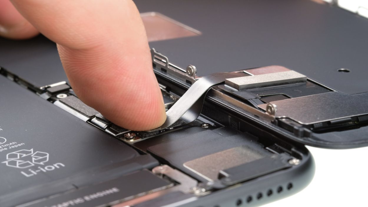
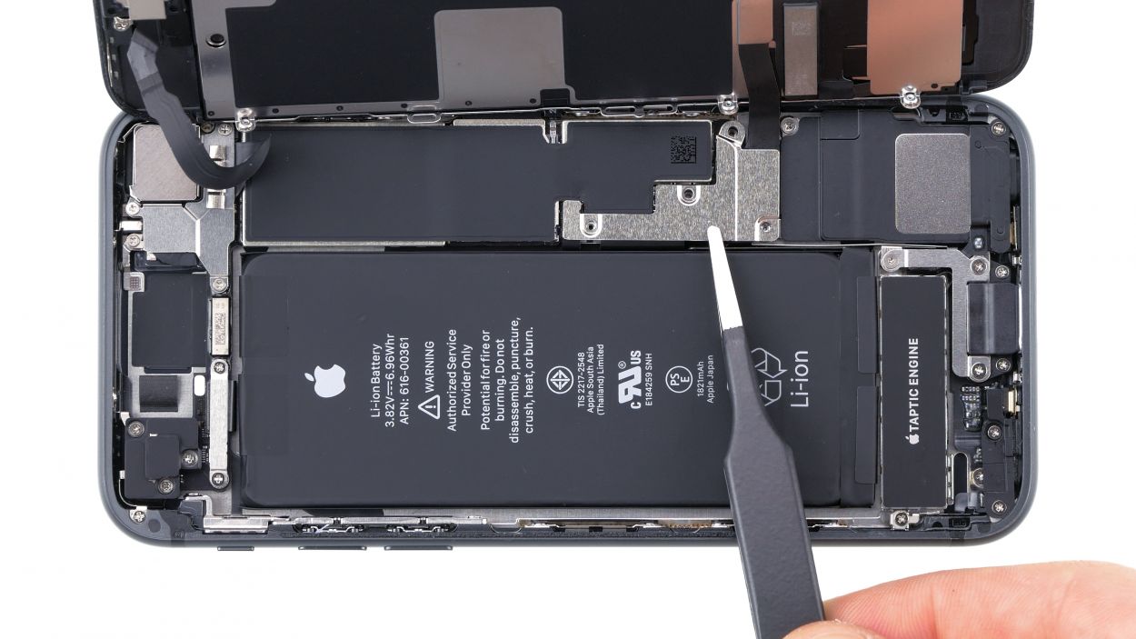
– First detach the small flex cable above the connector of the Taptic Engine with a spudger or tweezers.
– Then loosen the screws that secure the Taptic Engine.
– Carefully lever the Taptic Engine connector with a spudger and remove the Taptic Engine from your device.
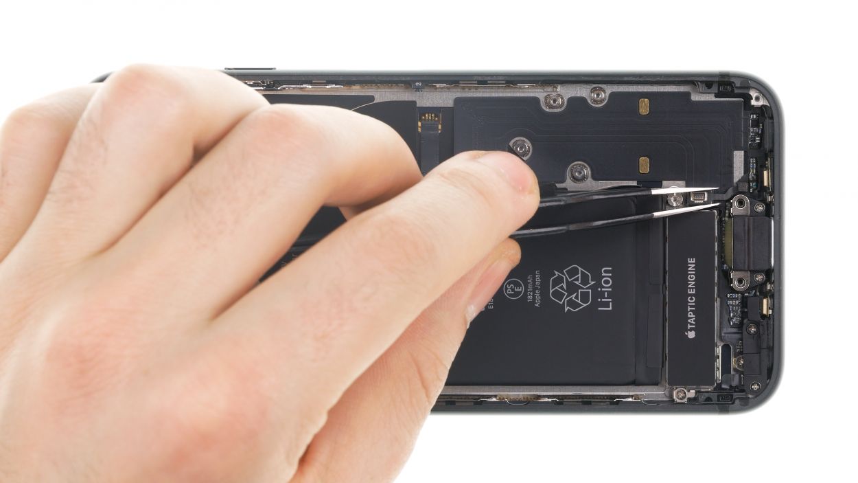
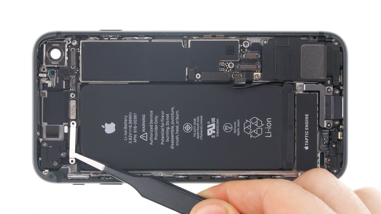
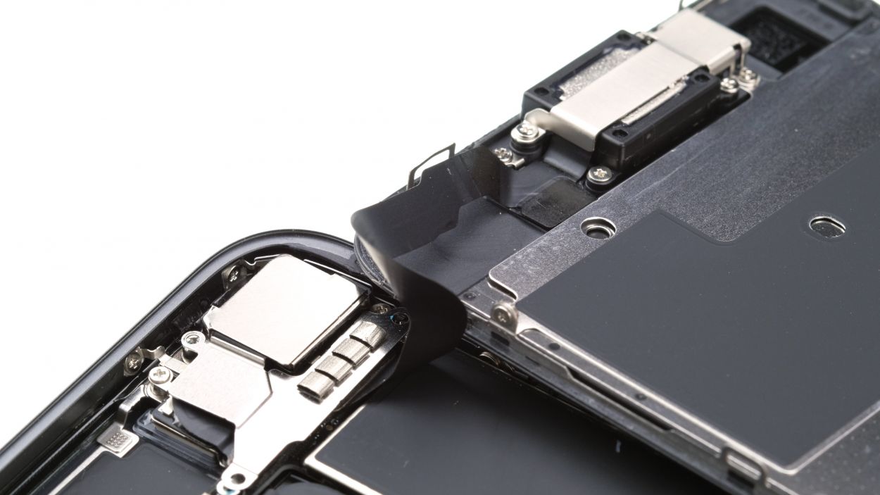
Step 18
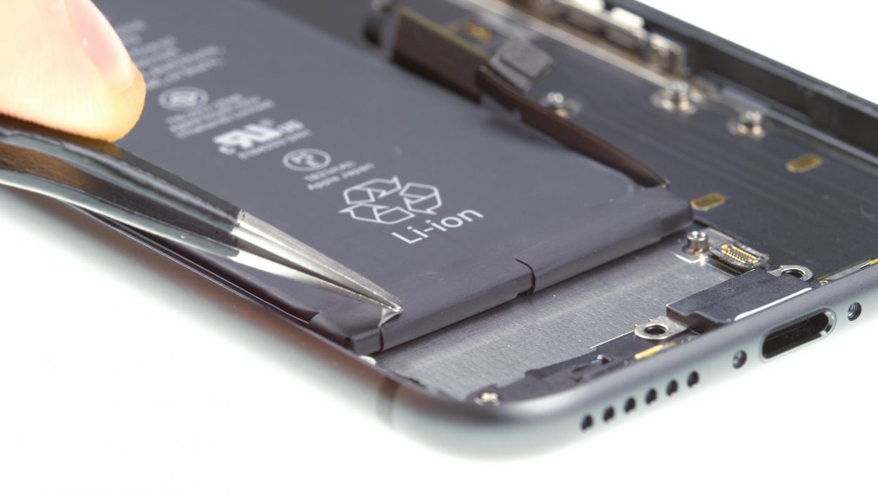
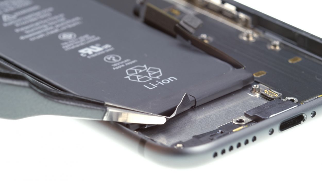

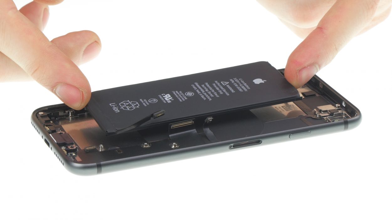
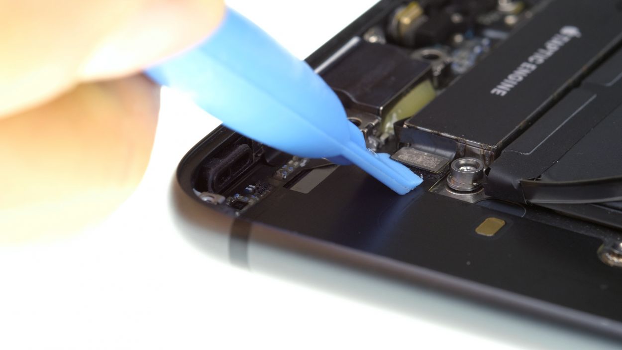
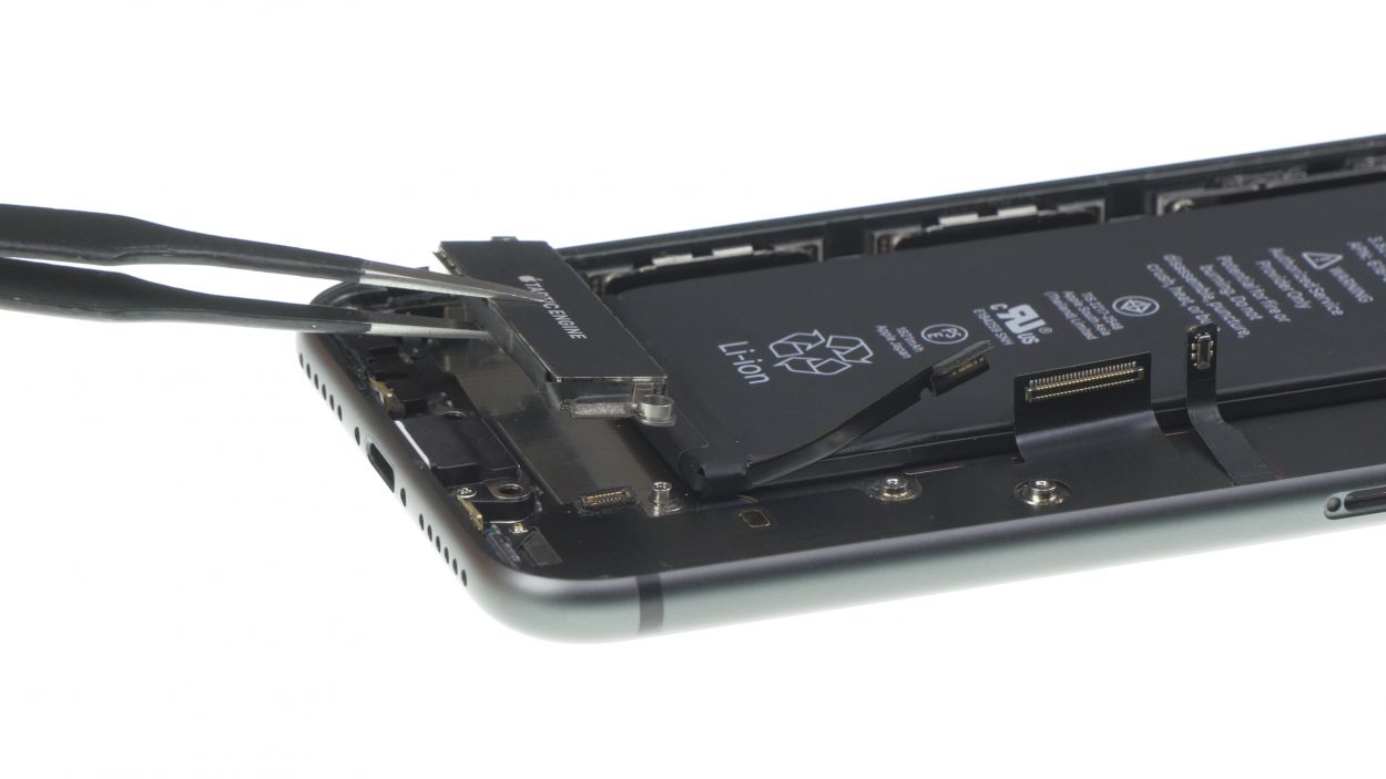
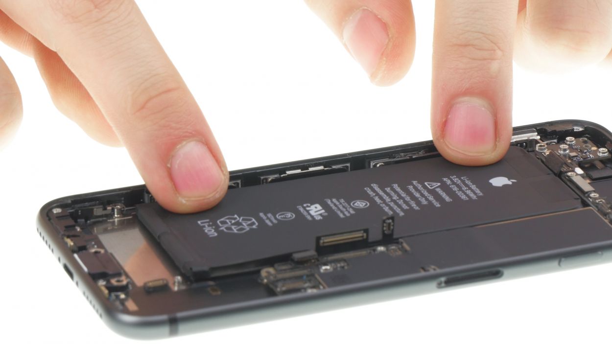
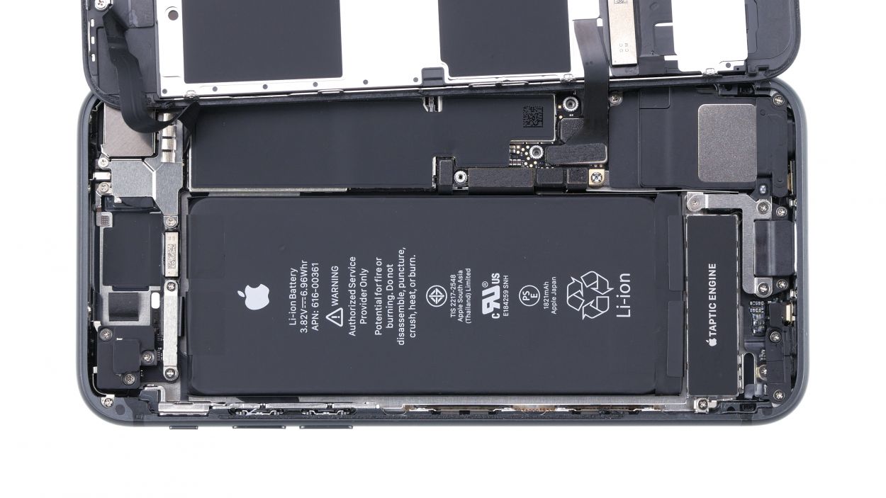
When pulling out the adhesive strips, take care not to damage the contact of the standby and volume cable.
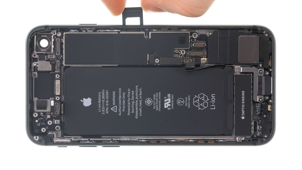
– Use tweezers or a spatula to remove the black tabs from the battery. Underneath are the white adhesive strips.
Tools Used
Step 19
1 × 1.7 mm Phillips
1 × 1.9 mm Phillips
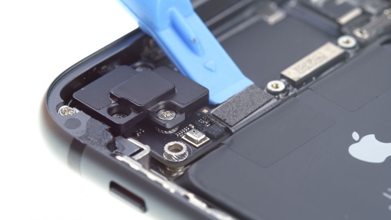
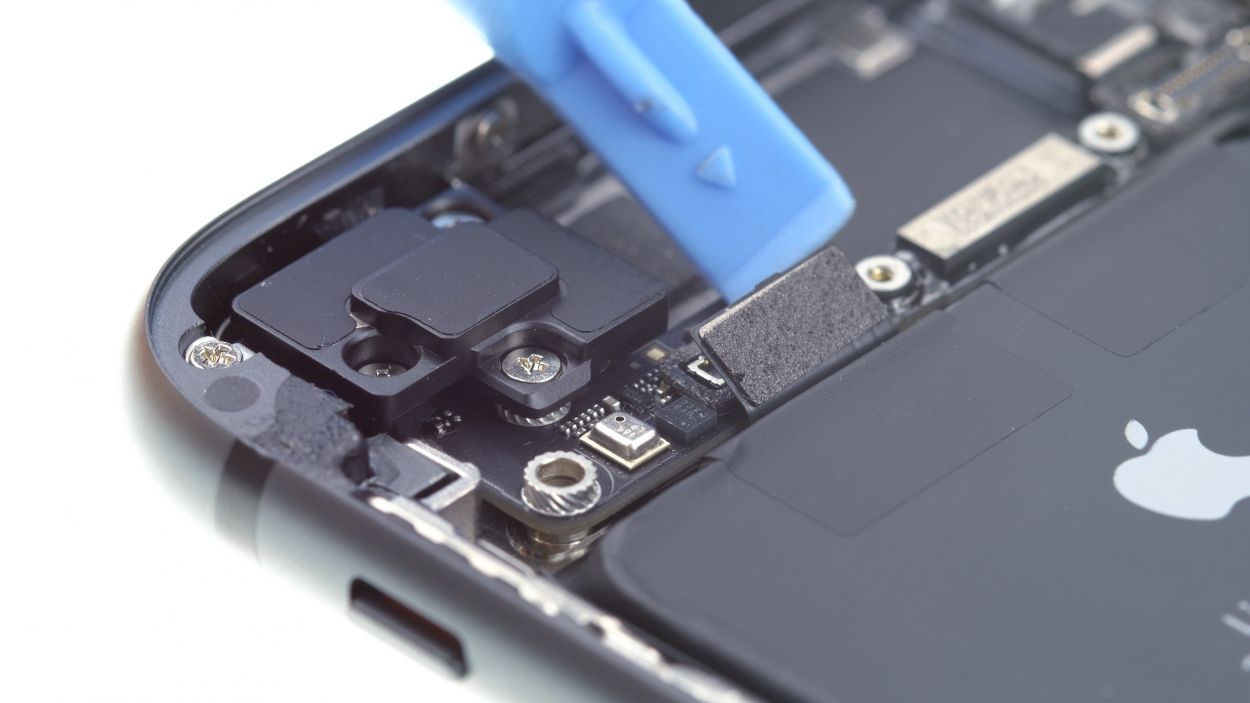
– Loosen the two screws on the barometric vent like a pro!
– Now, with a gentle touch, use your tweezers to lift off the barometric vent. It’s got a little glue holding it on, but you’ve got this!
Tools Used
Step 20
2 × 2.1 mm Phillips
3 × 1.2 mm Phillips
The two screws, which are screwed into the edge of the housing, are hidden under black stickers.
– Now remove the Phillips screws.
Step 21


1 × 2.4 mm Standoff
2 × 1.6 mm Phillips
1 × 2.6 mm Phillips
2 × 2.3 mm Phillips
Heating the cable briefly will make it easier to remove it from the back cover.
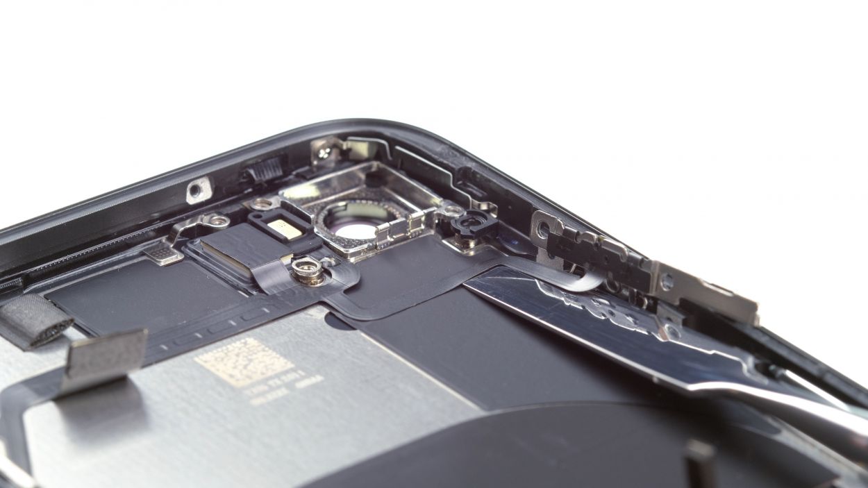
– First remove the stand-off screw on the flash cover.
– Then remove the five Phillips screws that attach the volume control cable.
Tools Used
- heat gun to heat parts that are glued on so they’re easier to remove.
In most cases, you can also use a hairdryer.” rel=”noopener”>Heat gun - Wiha PicoFinish Phillips Screwdriver PH00
Step 22
6 × 1.6 mm Phillips
– Each of the three mounting clamps is secured with two Phillips screws. Remove them.
– Two of the clamps have a protective film. Remove and reuse it.
Step 23

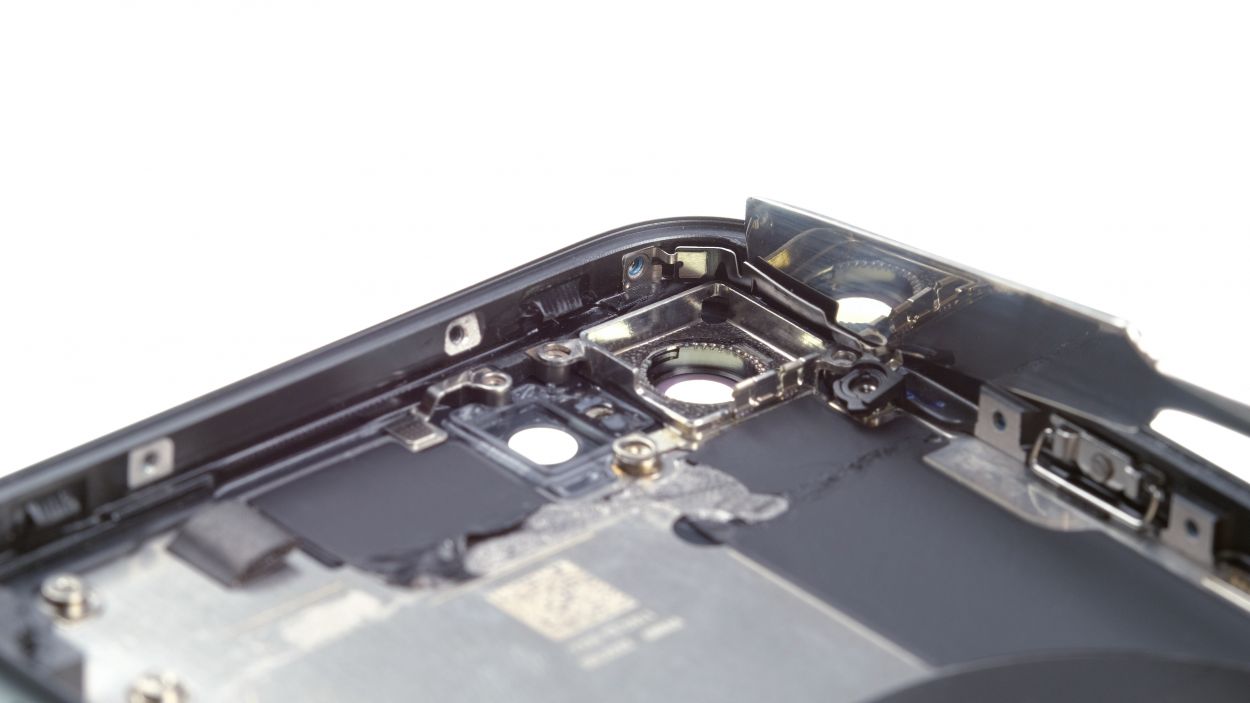
1 × 1.3 mm Phillips
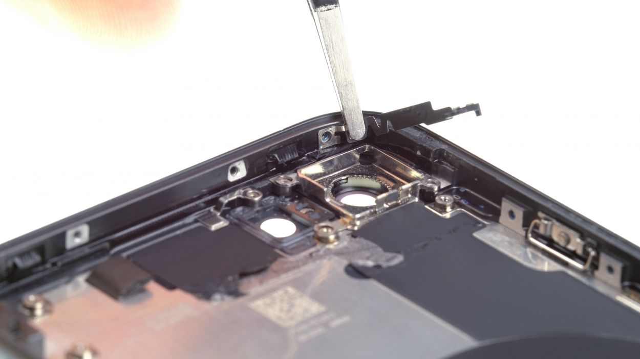
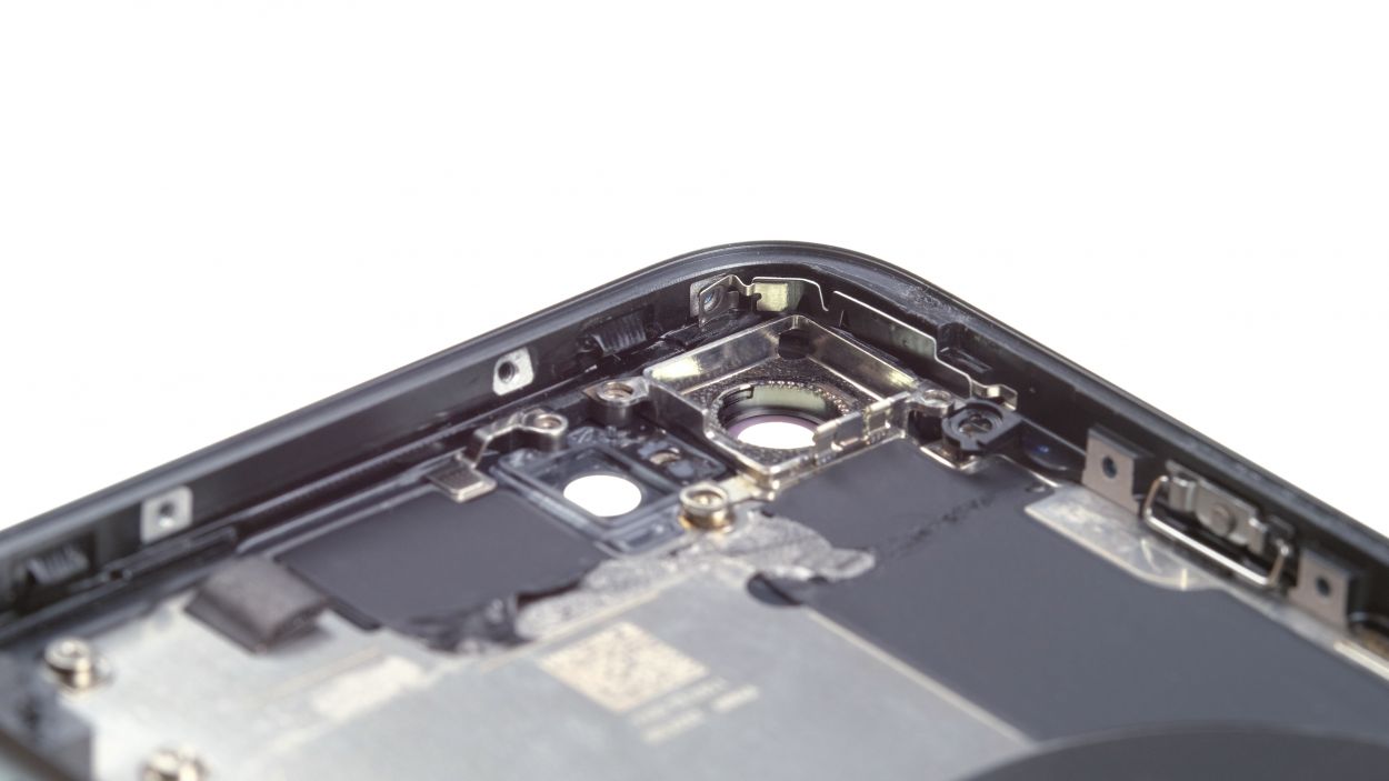
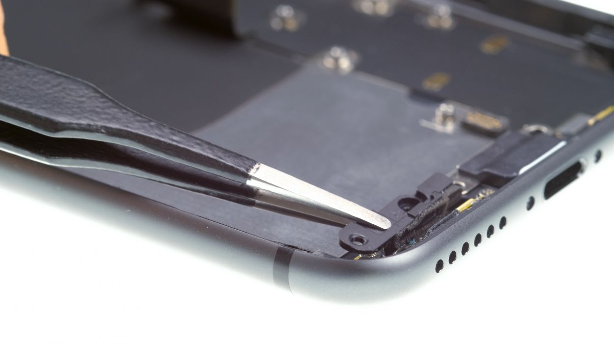
– Remove the Phillips screws screwed into the side of the back cover.
– Use a steel spatula to loosen the guide rail of the iSight camera and then remove it.
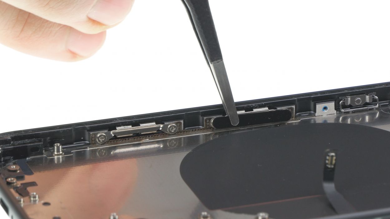
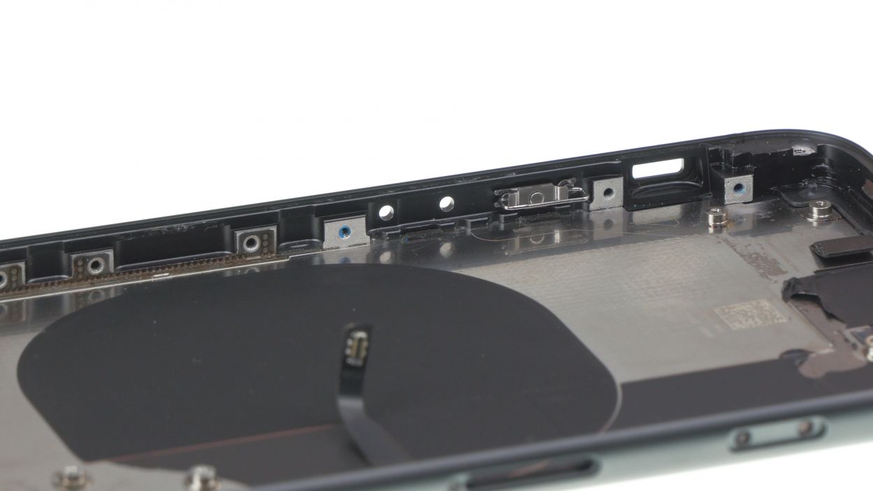
Step 24
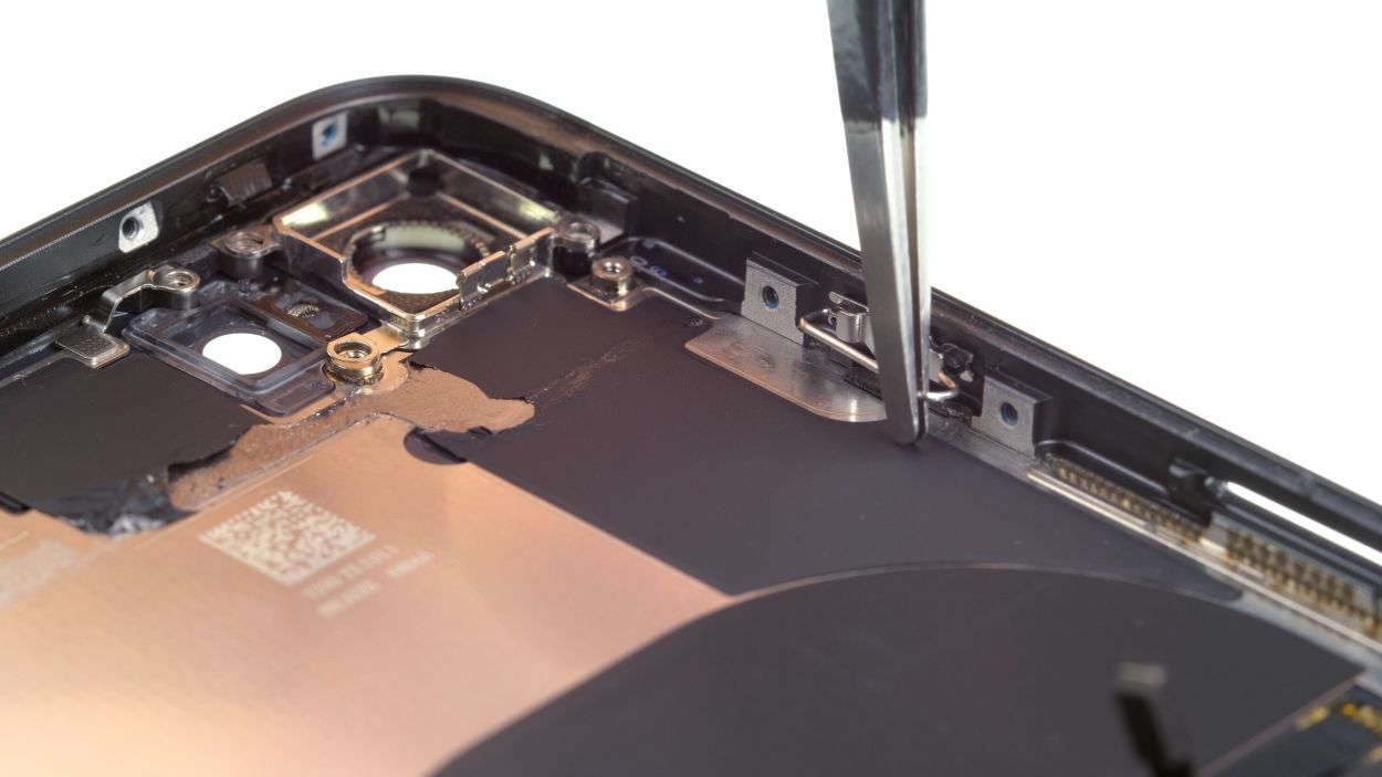
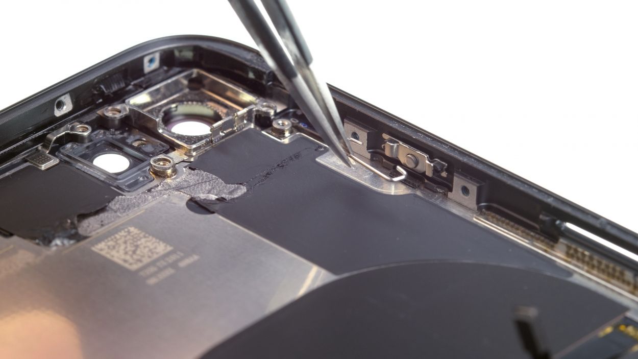
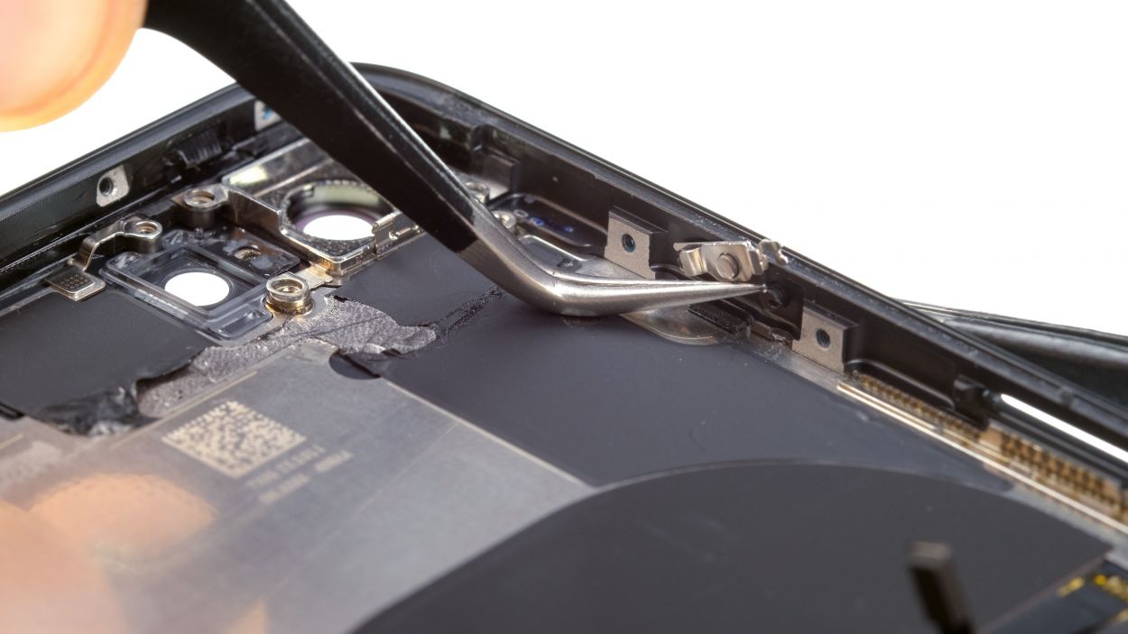
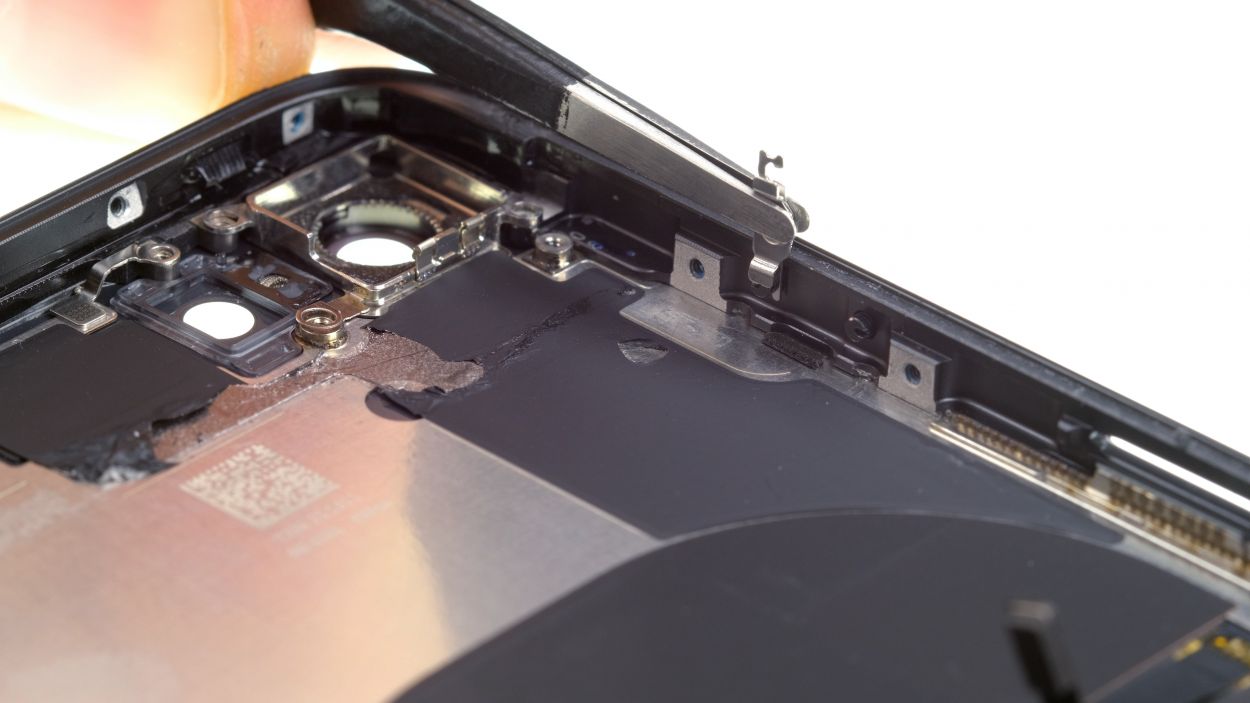
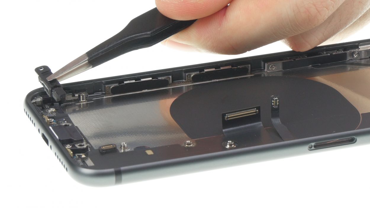
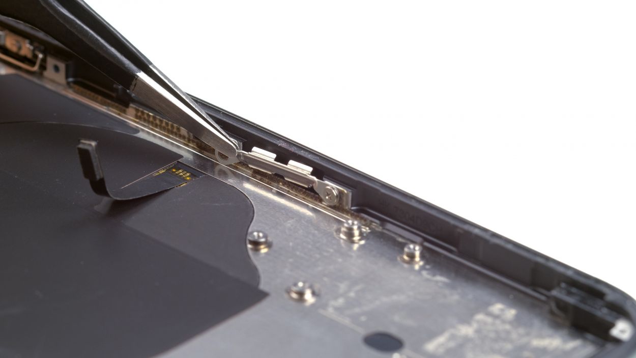
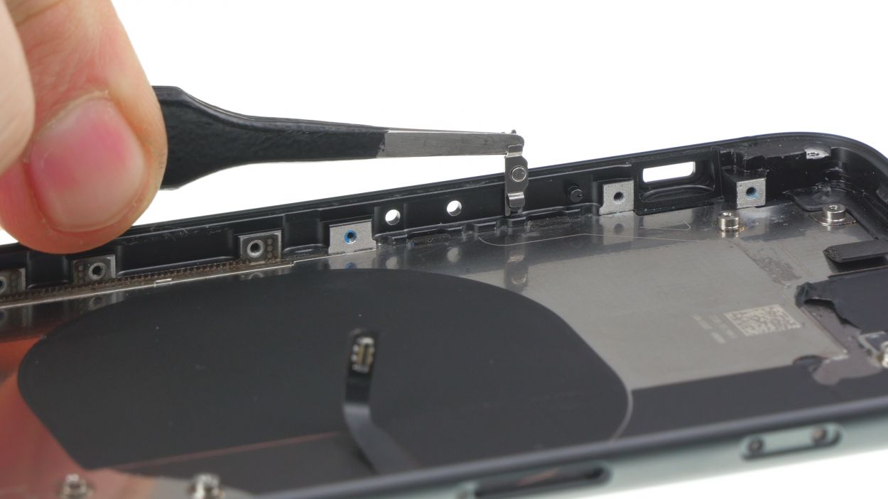
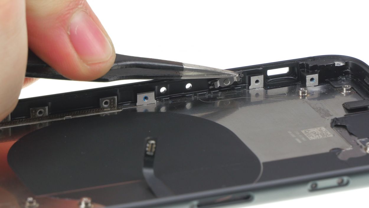
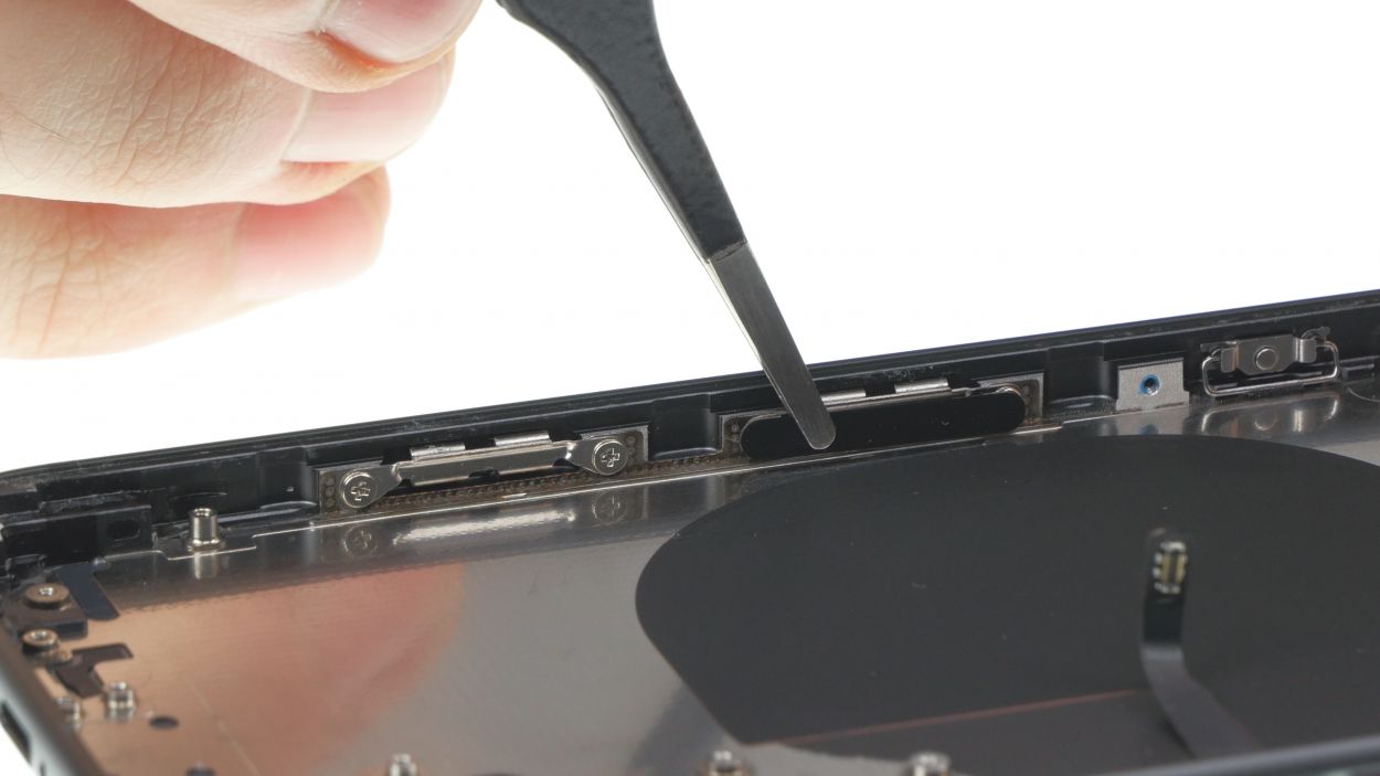
– Using tweezers, carefully pull the brackets of the standby button out of the frame of the back cover.
– Press the button bracket vertically upwards from one side before pulling it upwards from the back cover frame.
– Now you can press the standby button out of the frame from the inside.
– You can do the same with the volume buttons.
Tools Used
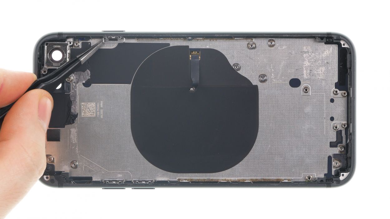
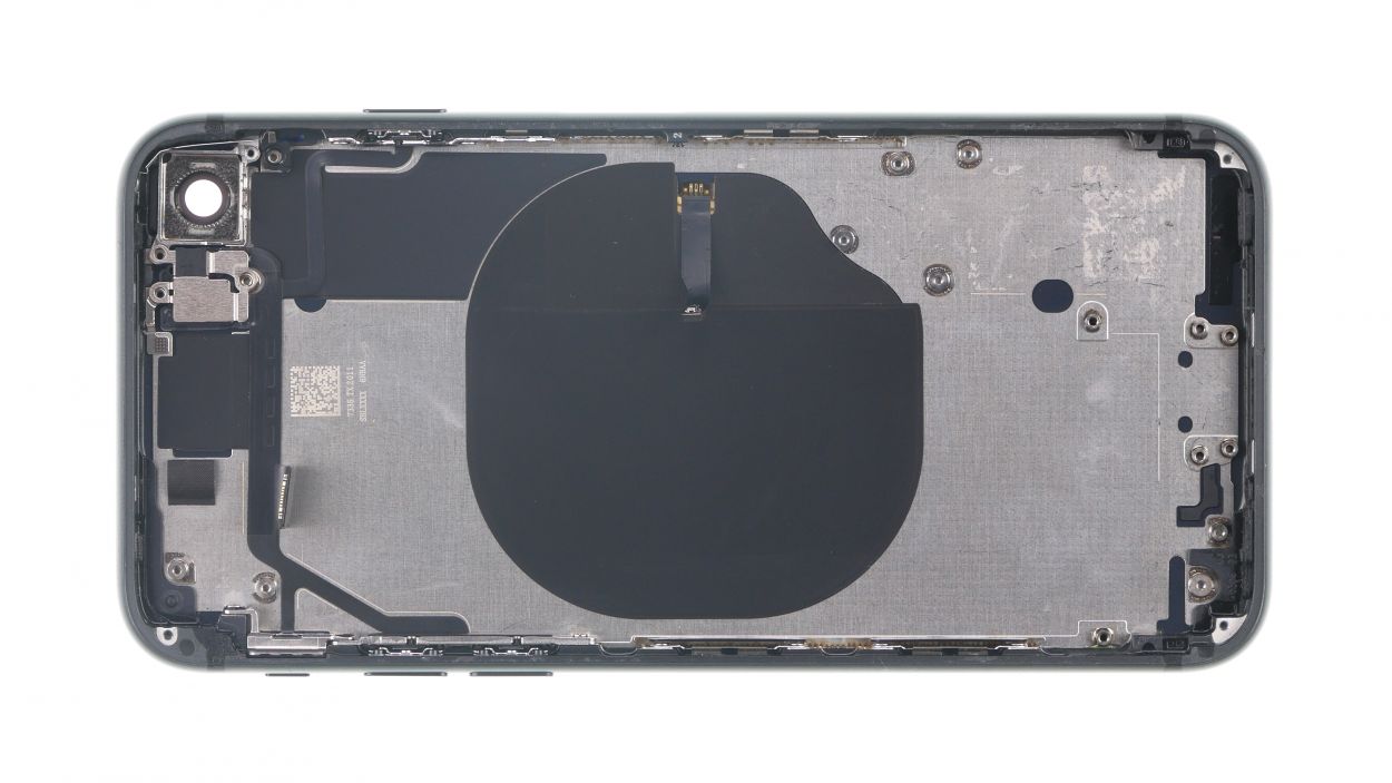
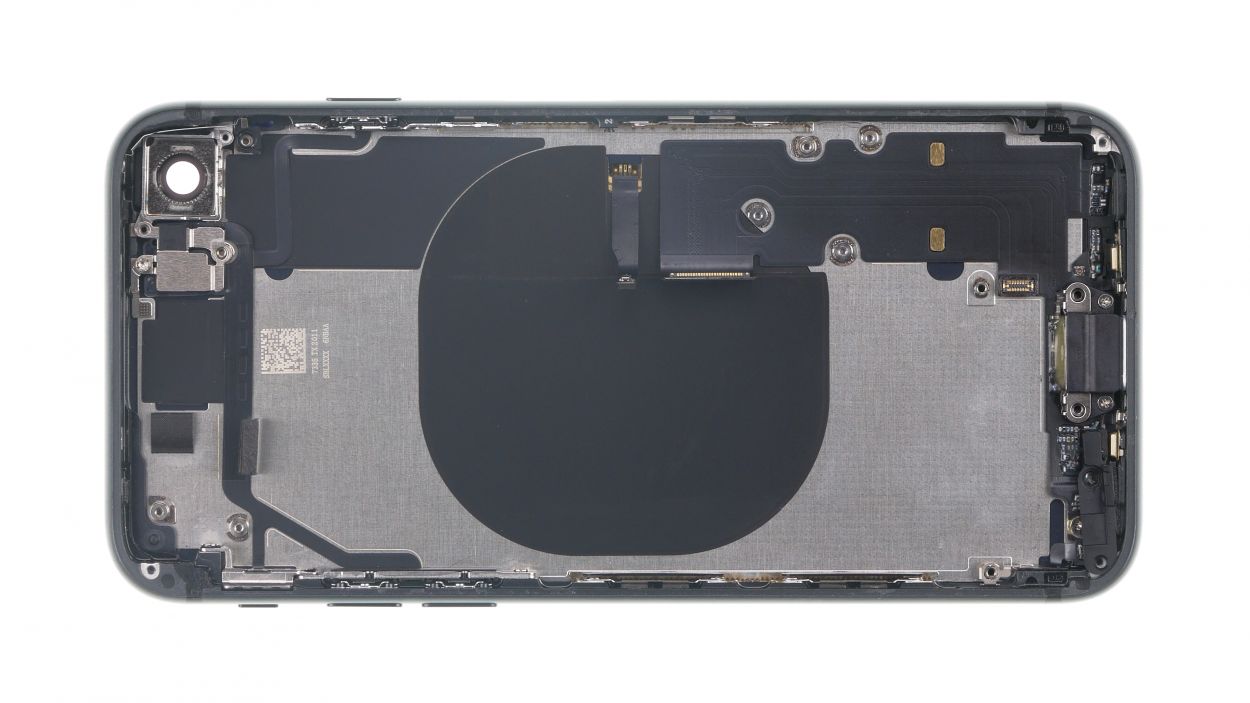
Step 25
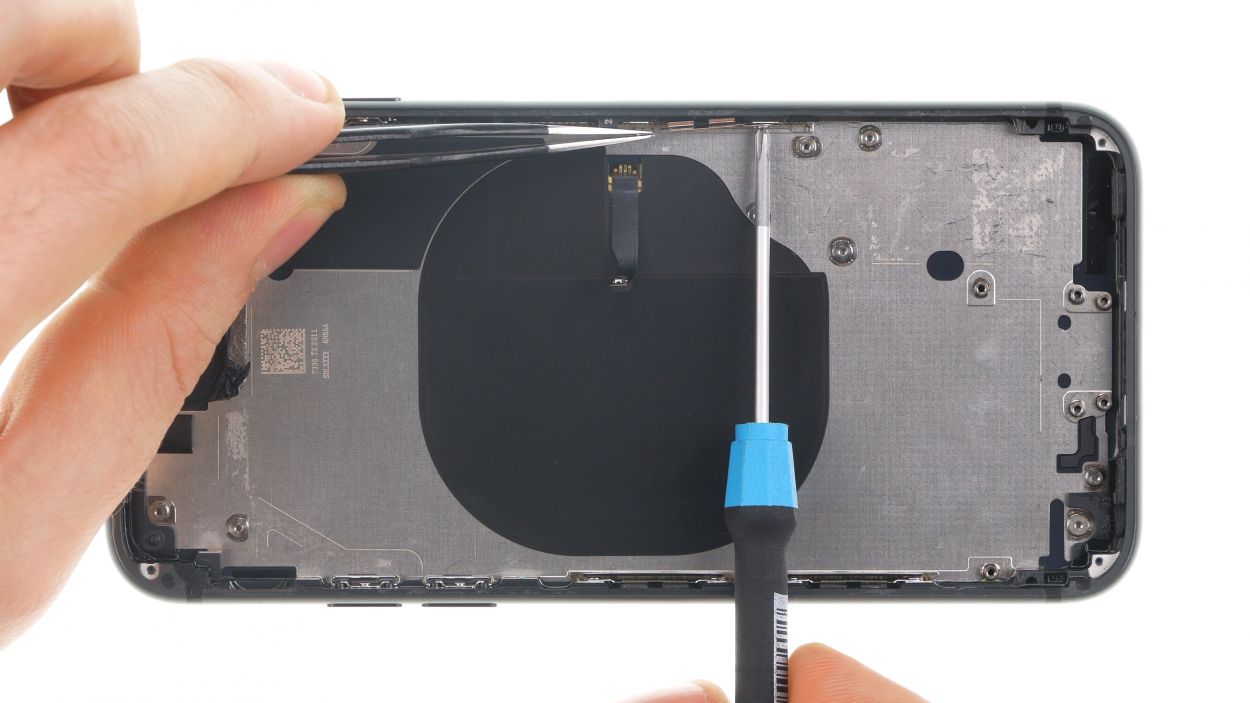
Alright, let’s get this party started! Before we dive in, make sure to have a blast with our fun and quirky repair guide. Remember, if you ever feel lost or need a helping hand, just drop a comment and our team will be there to lend a hand! Now, let’s get that iPhone 8 back cover swapped out like a pro! Have a great time!
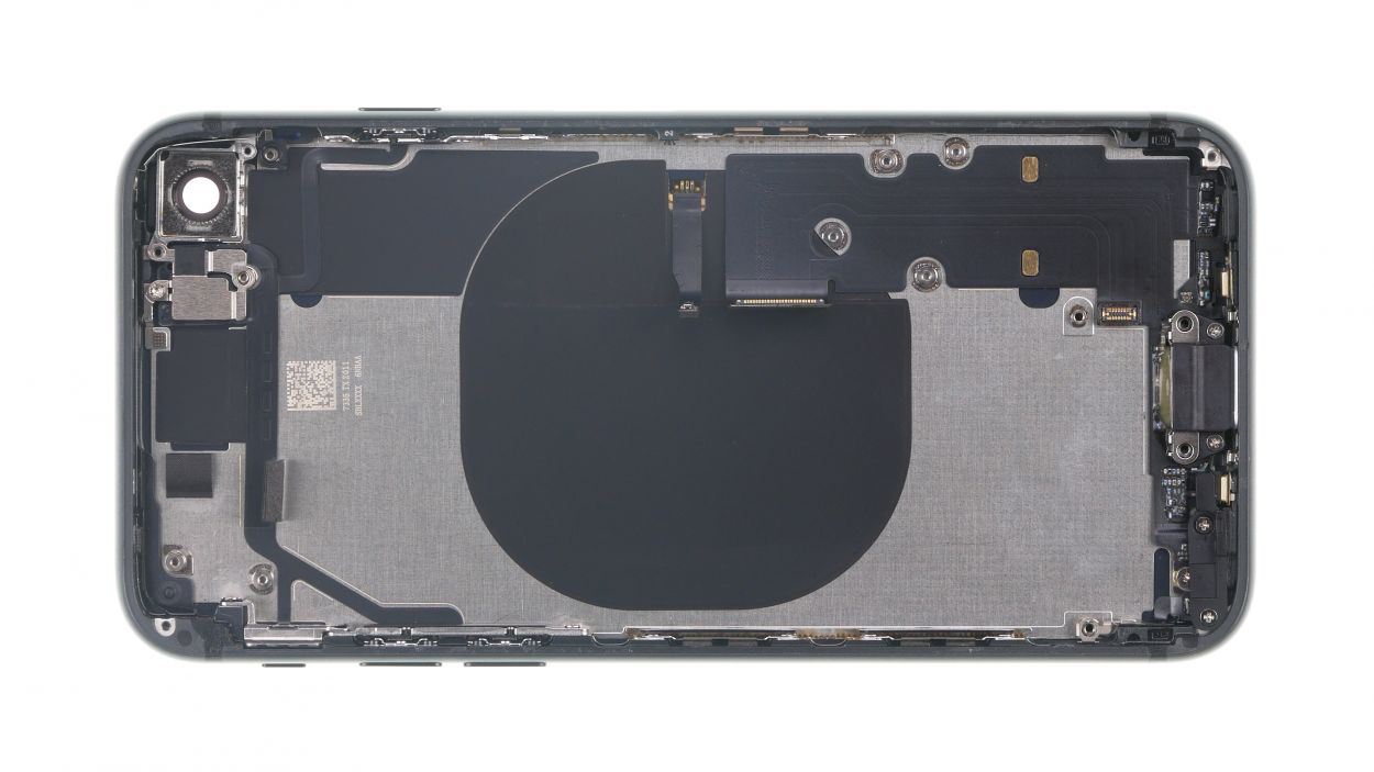
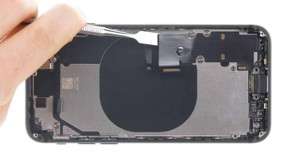
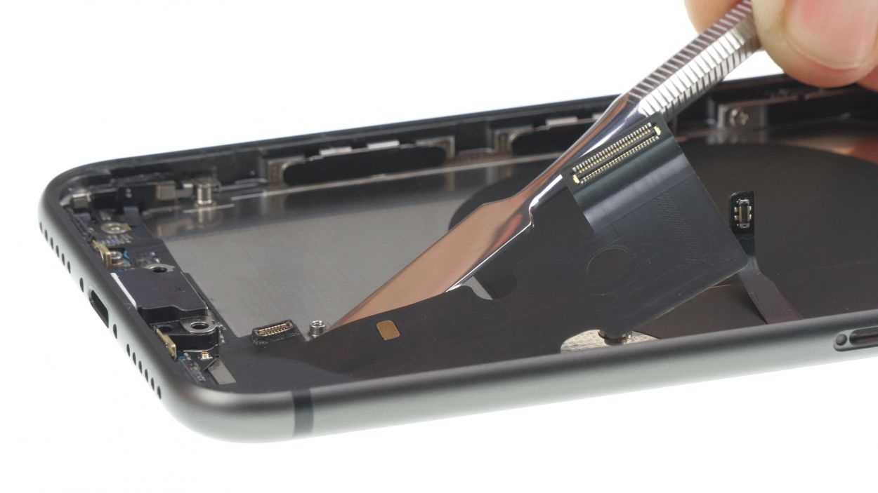
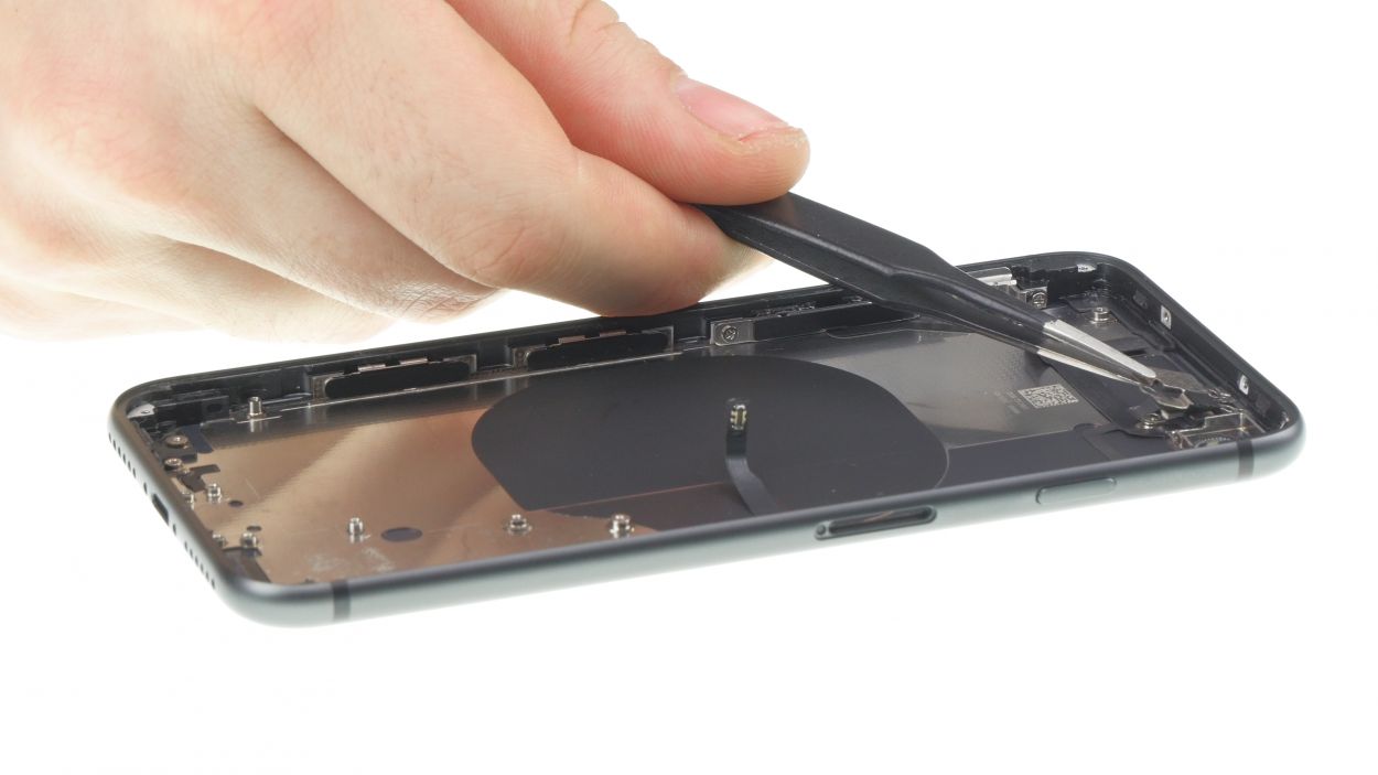
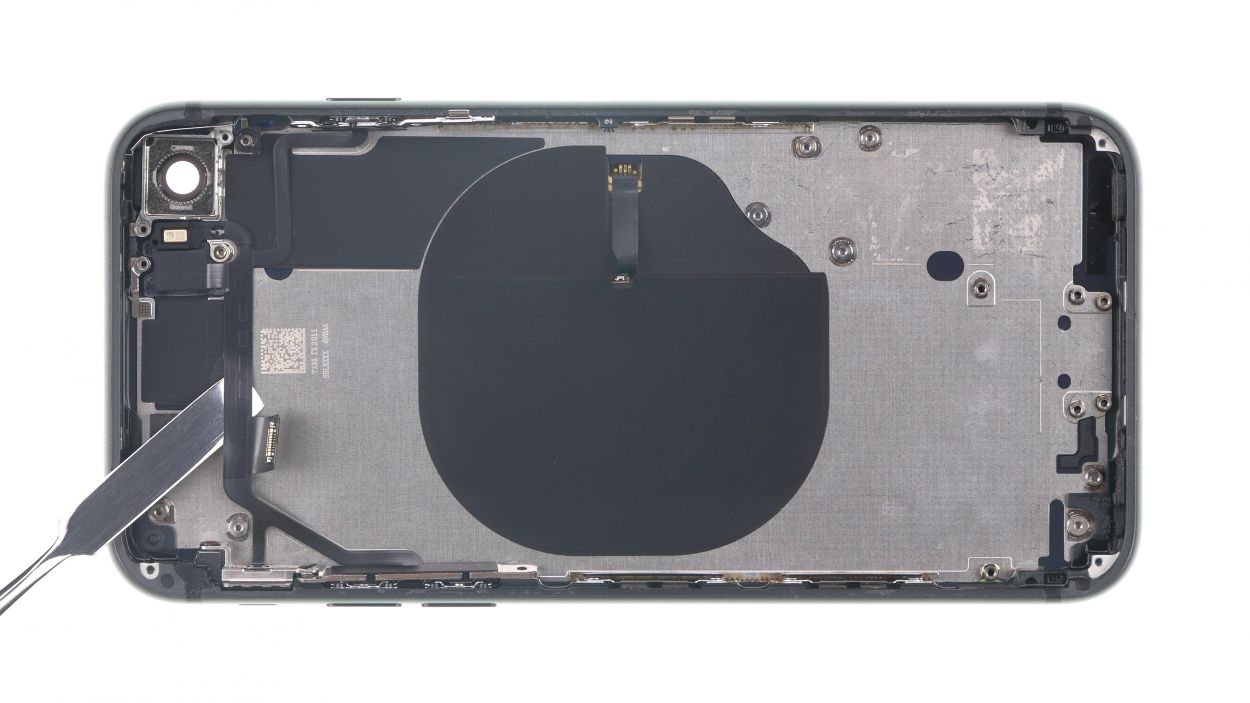
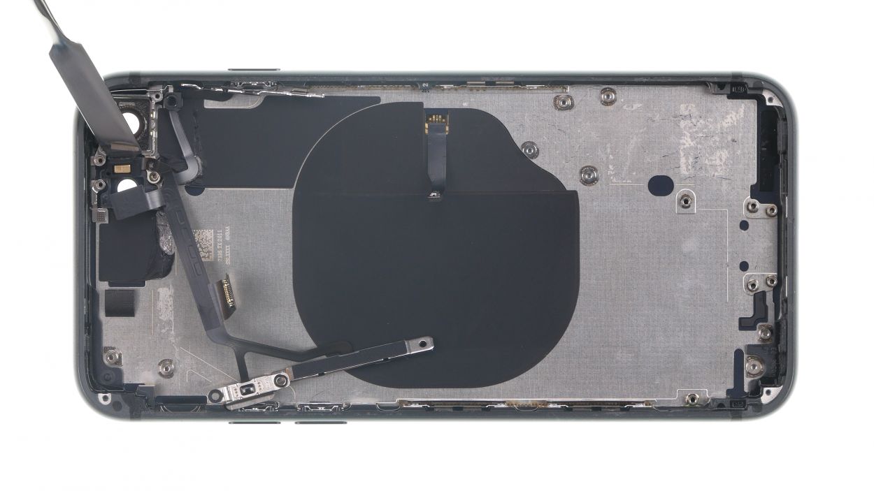
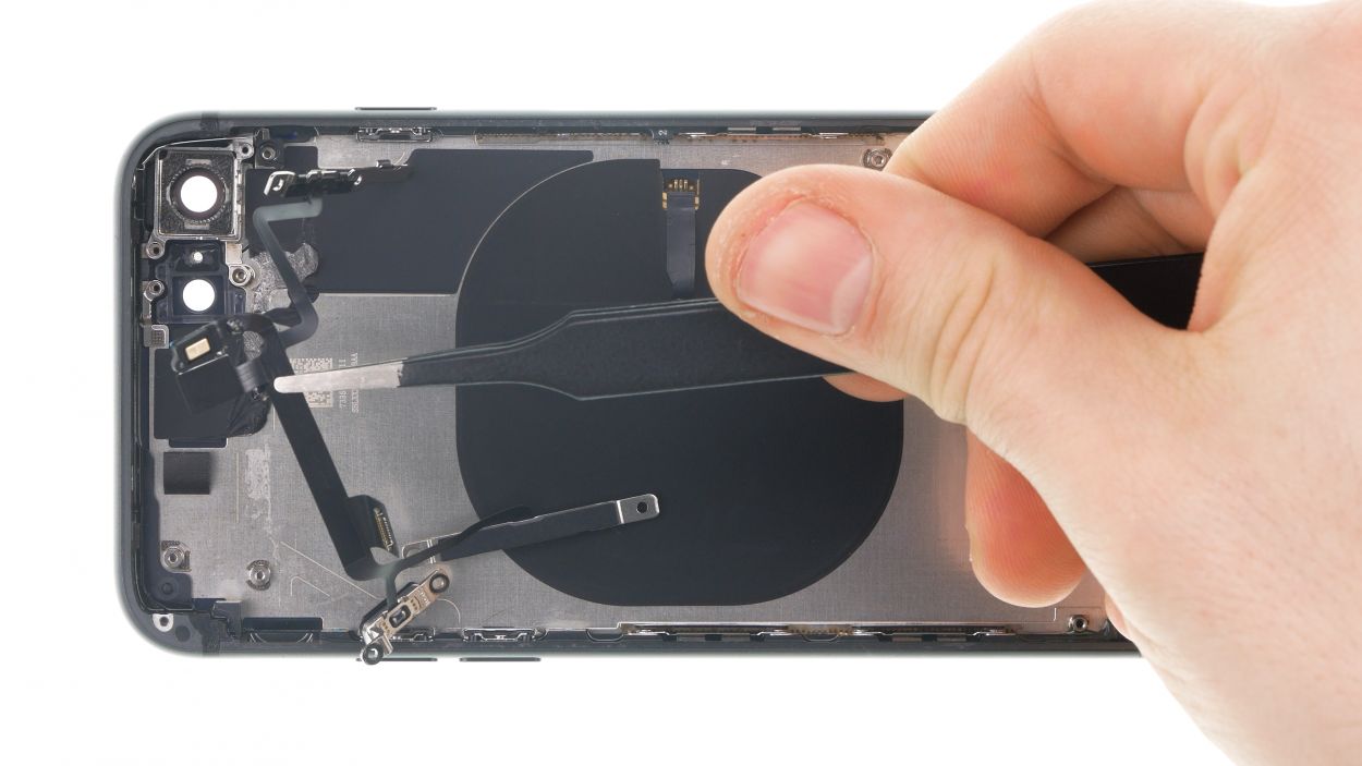
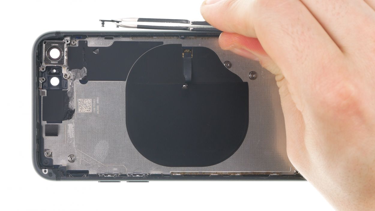
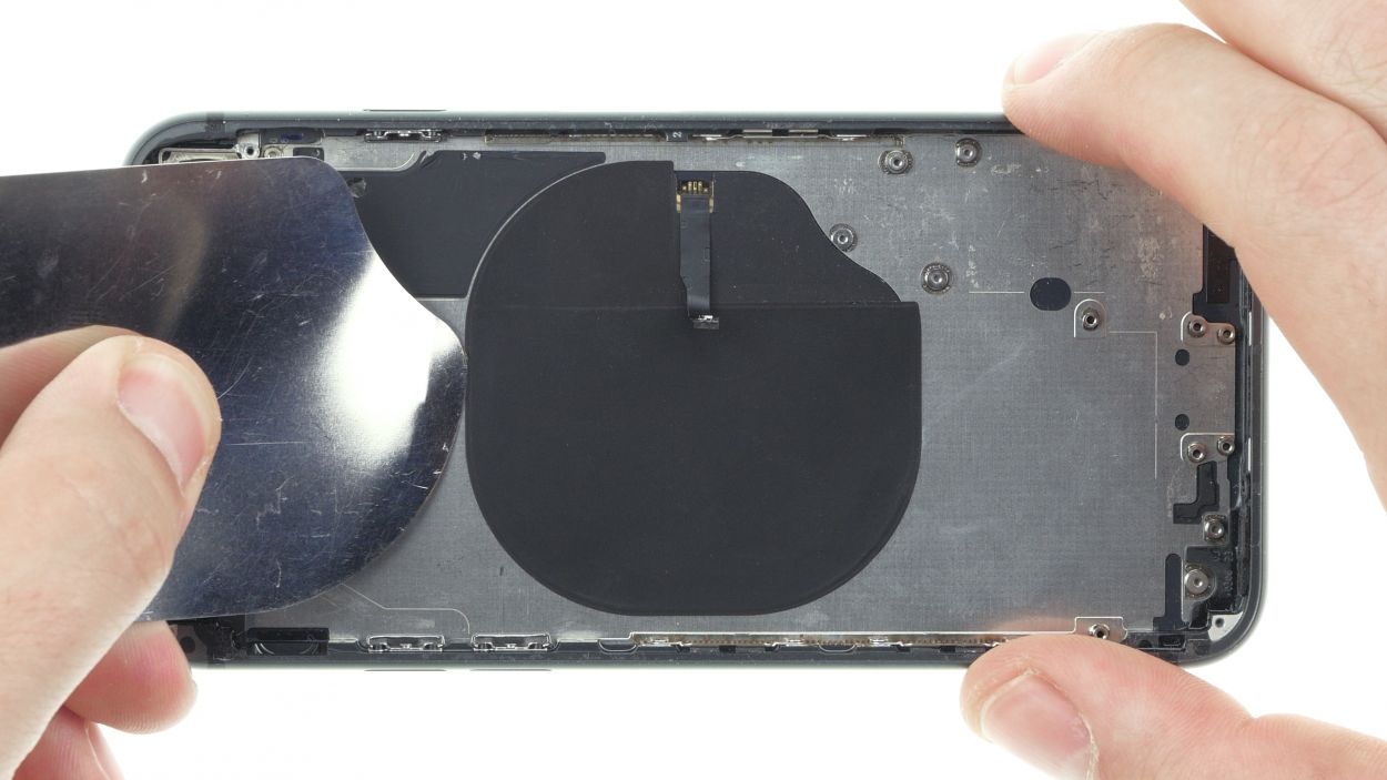
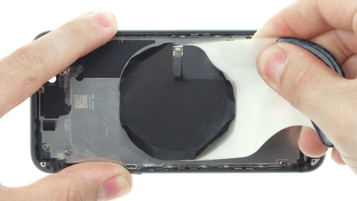
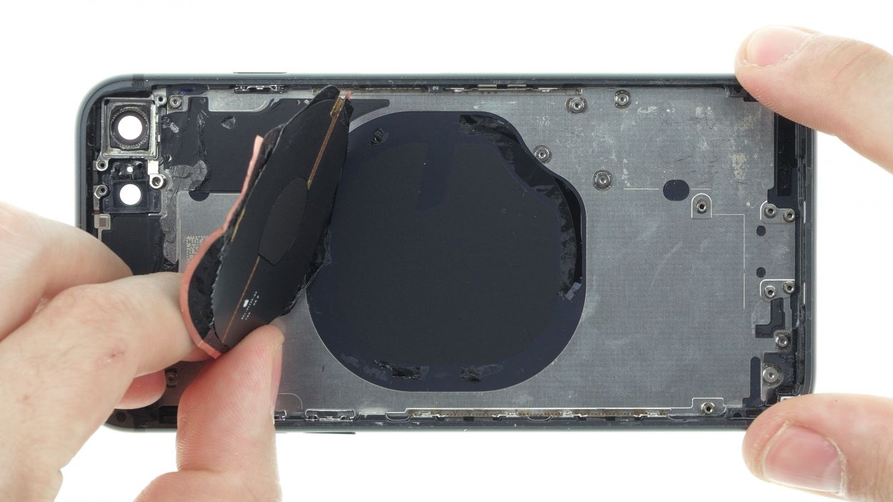
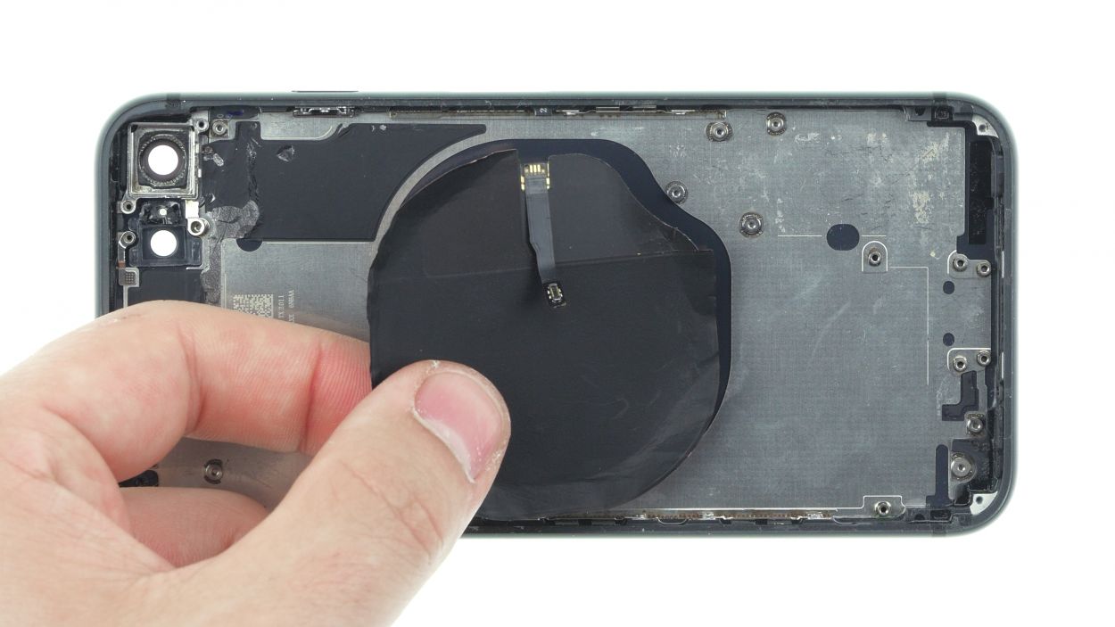
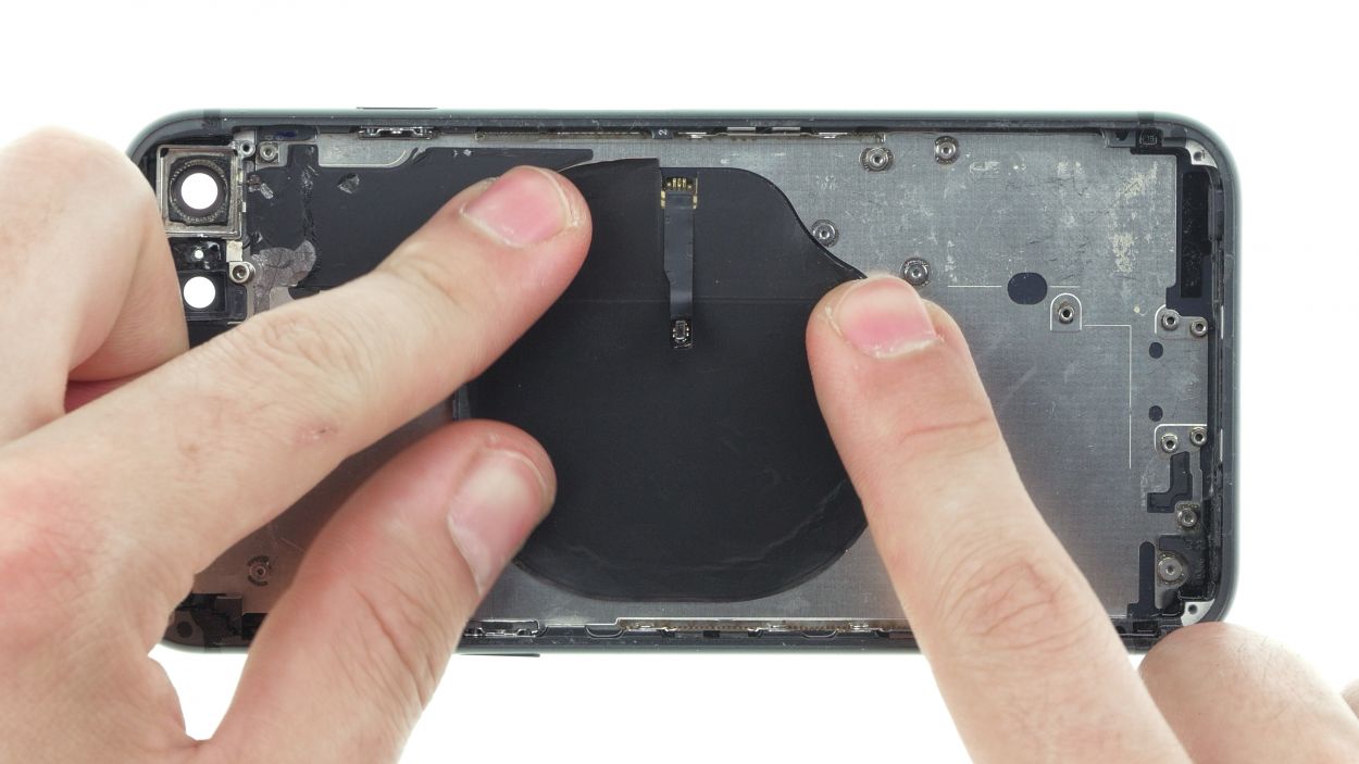
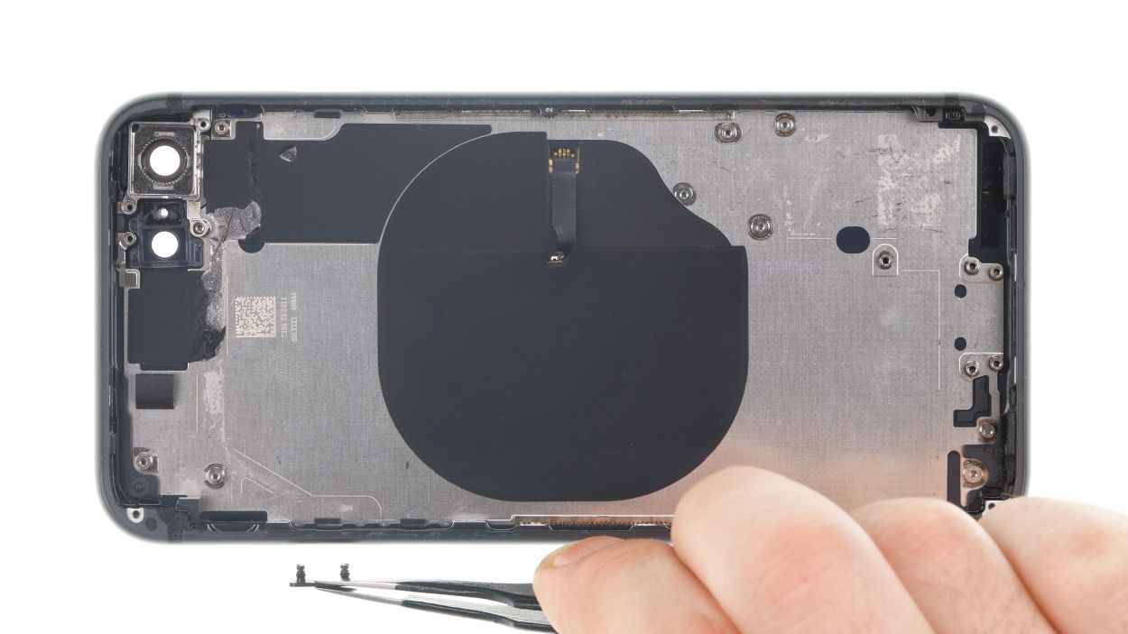
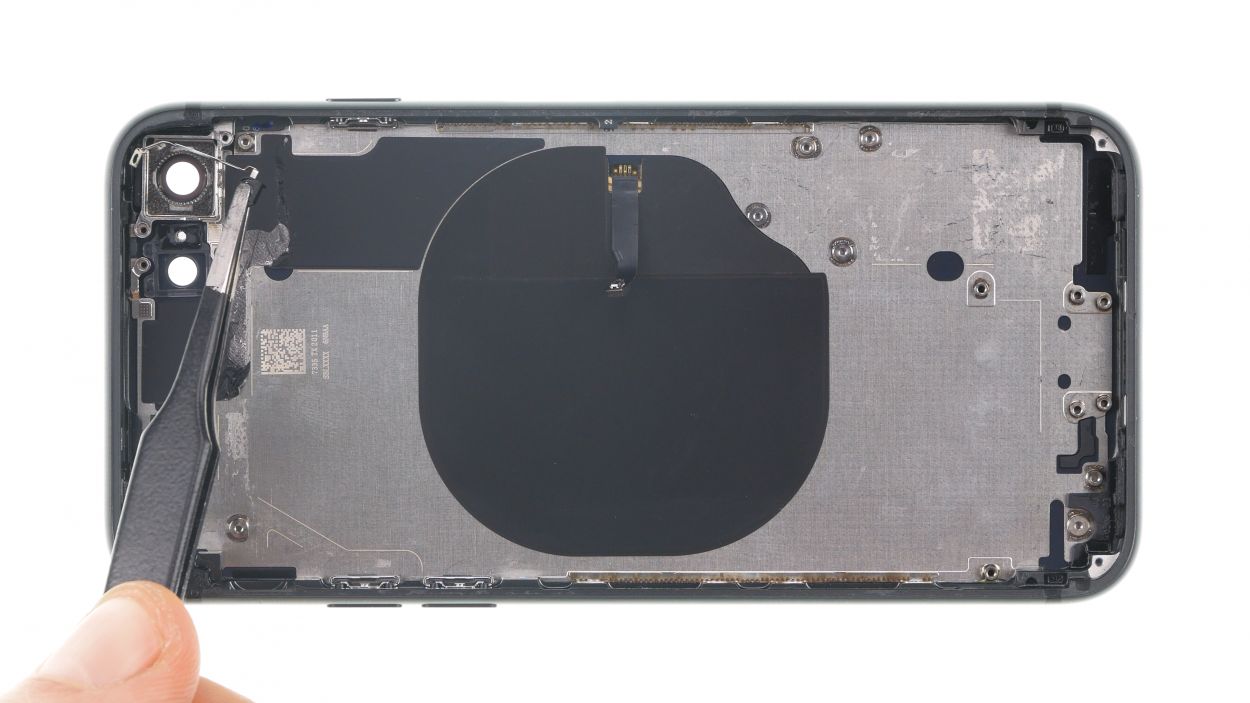
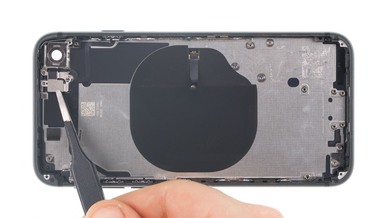
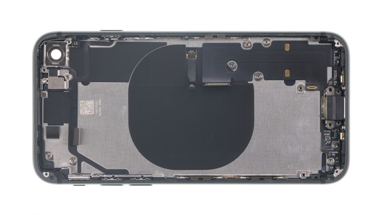
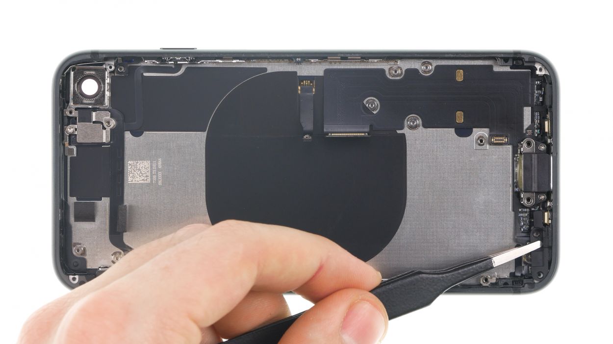
– First, heat the edge of the charging coil with hot air to make it easier to remove the adhesive that holds the coil to the back cover.
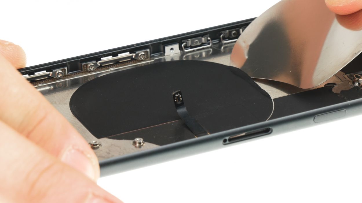
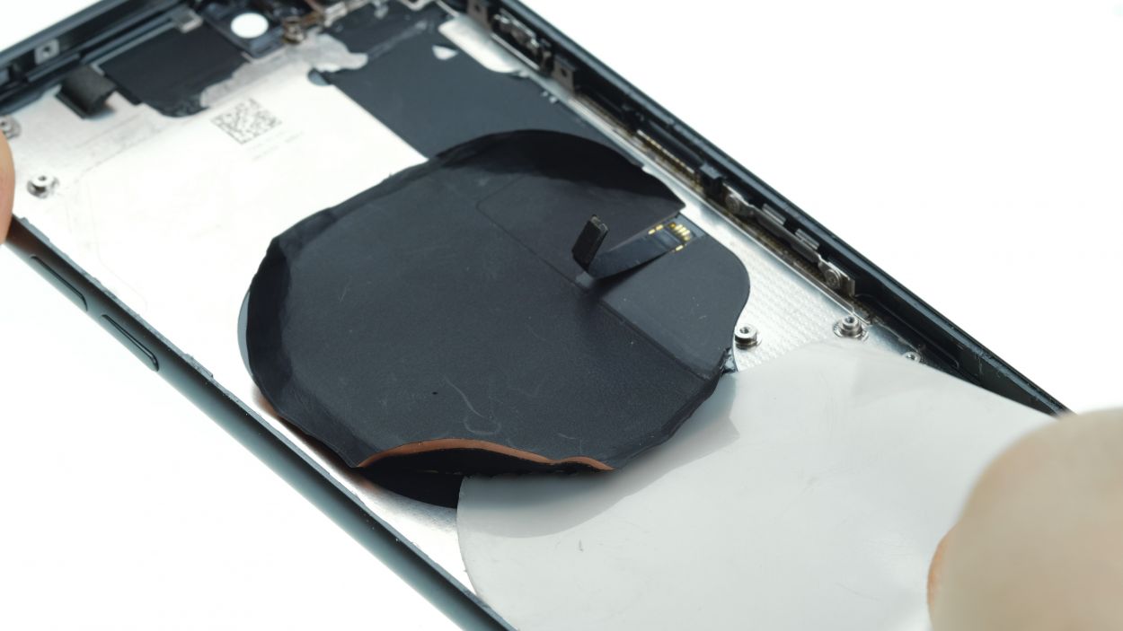
– Then remove the edge of the coil from the backcover by running a flat, stable tool under it.
Tools Used
- heat gun to heat parts that are glued on so they’re easier to remove.
In most cases, you can also use a hairdryer.” rel=”noopener”>Heat gun - iFlex Opening Tool
- iPlastix Opening Tool
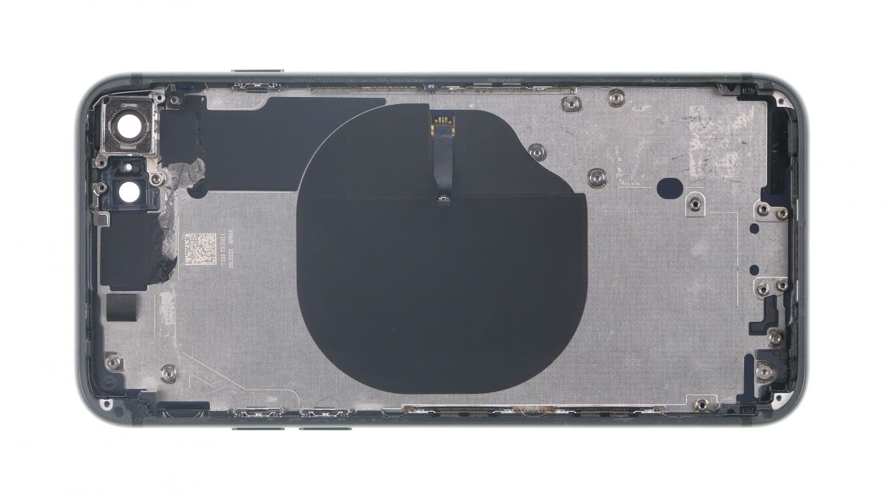
Step 26
Dichtungen
Plastikführung
You also have to transfer the small plastic pin for the SIM holder into the new back cover.
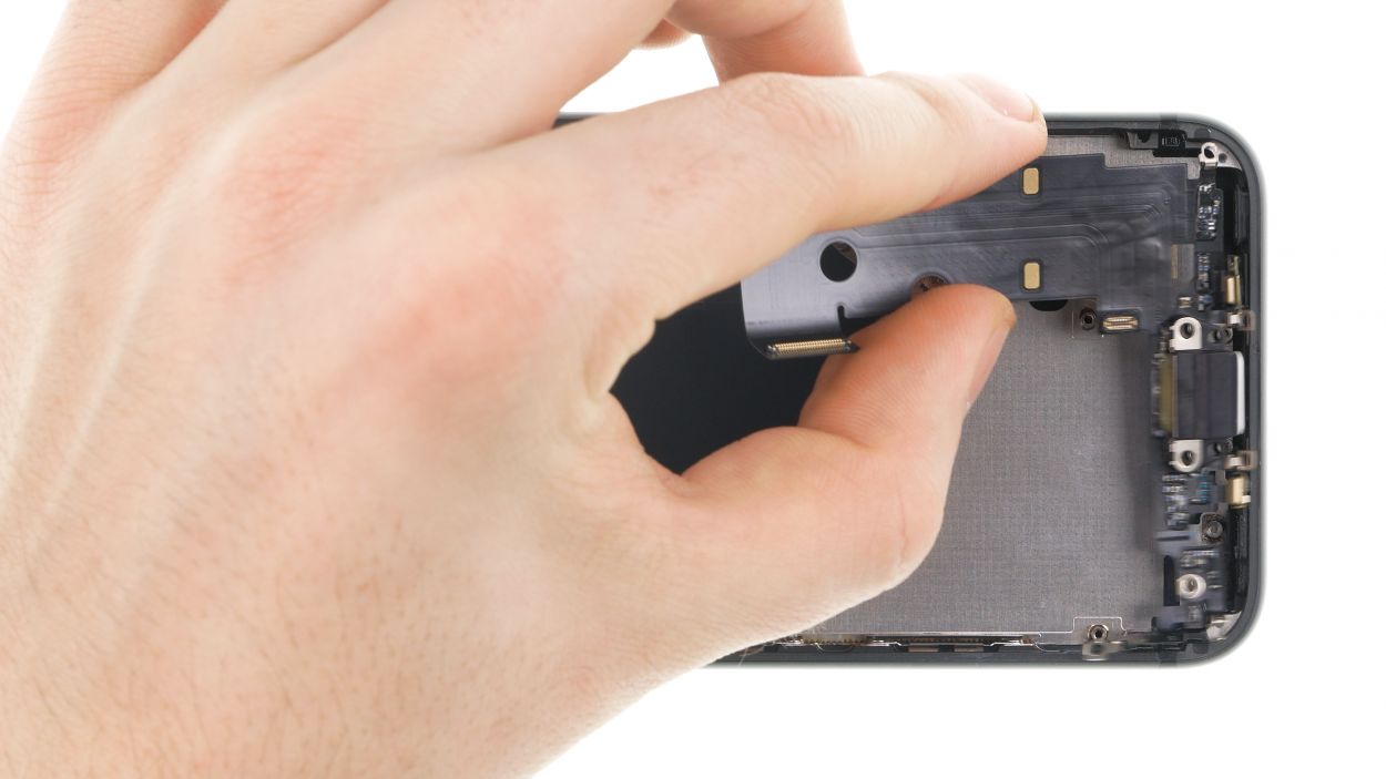
– Remove all parts that you need to transfer from the old back cover.
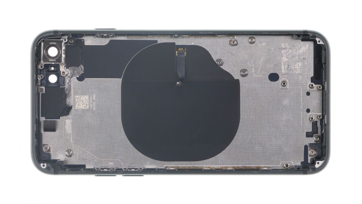
Step 27
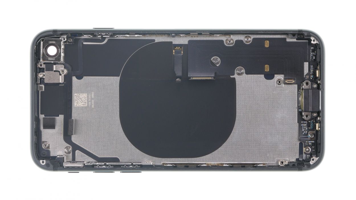
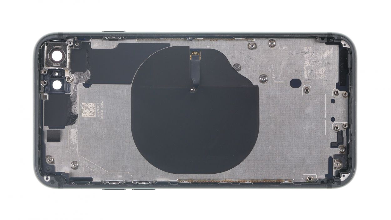
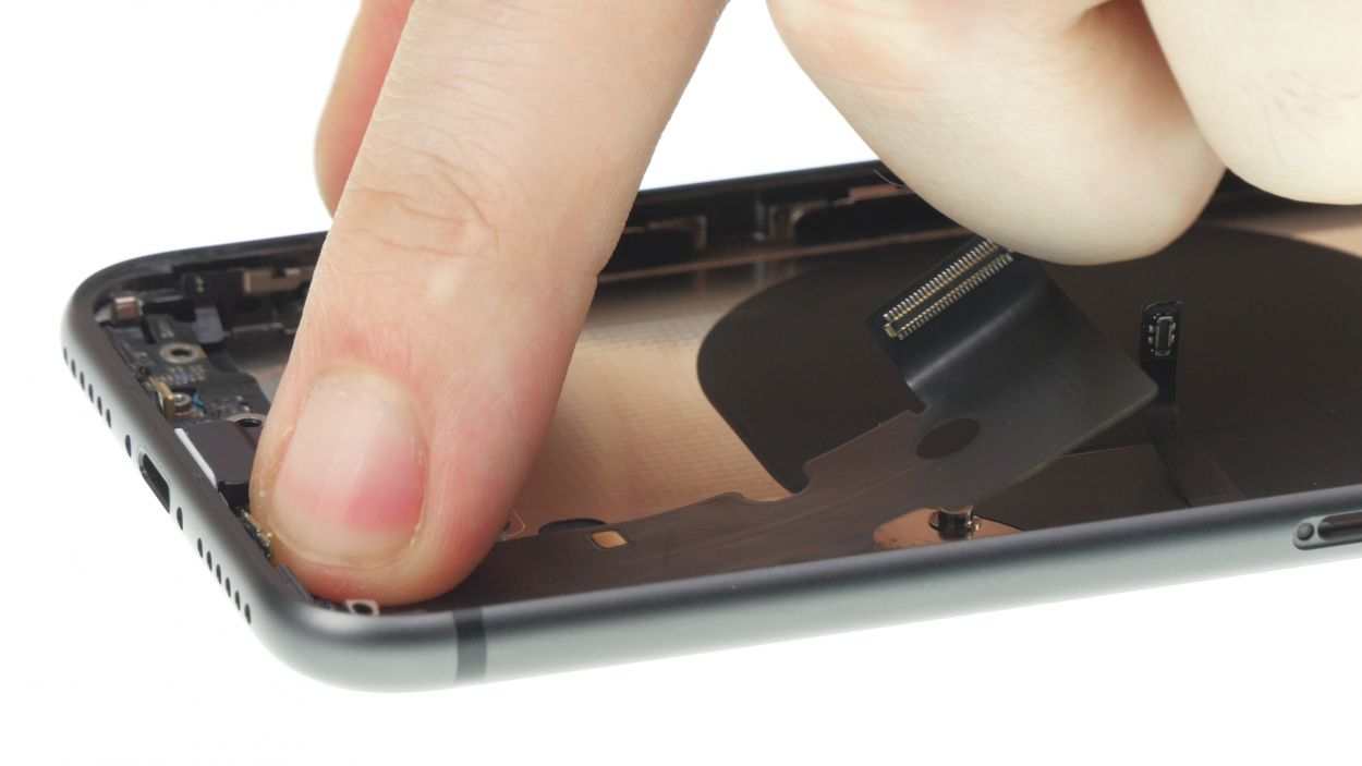
– Paste the charging coil to the back cover as flatly as possible.
– Position it correctly so you can connect it to the logicboard later.
– If the glue doesn’t hold properly, heat it a little and press it on.
Step 28
– First press the buttons from the outside inwards into the frame of the back cover.
– Insert the button bracket from vertical first, then turn it down sideways.
– Use the tweezers to hook the other button brackets into their openings.
– Proceed the same way for the volume buttons.
Step 29
1 × 1.3 mm Phillips
– Place the guide rail in its opening and screw it tight with the Phillips screw.
Step 30
6 × 1.6 mm Phillips
– Install the mounting clamps with two Phillips screws each. Make sure the clamps face the right direction.
Step 31

2 × 1.6 mm Phillips
1 × 2.6 mm Phillips
2 × 2.3 mm Phillips
1 × 2.4 mm Standoff
When inserting the flex cable, make sure that the cable lies flat, and that the microphone and flash are correctly aligned before you screw the flex cable on.
– Put the flex cable of the standby button and the volume buttons back into the back cover and fix it with the five Phillips screws.
– Check the pressure sensitivity of the buttons after tightening the screws and readjust if necessary.
– Press the entire cable set, including microphone and flash light, firmly into the case.
– Fix the bracket plate of the flash light with the stand-off screw.
Step 32
2 × 2.1 mm Phillips
3 × 1.2 mm Phillips
– Drücke das Flexkabel des Lightning Connectors an seiner ursprünglichen Stelle flach auf dem Boden des Backcover fest.
– Presse die zwei Mikrofone, die am Flexkabel integriert sind, in ihre Führungen am Rand des Backcovers.
– Fixiere nun den Lightning Connector mit allen zuvor gelösten Schrauben.
Step 33
1 × 1.7 mm Phillips
1 × 1.9 mm Phillips
– Put the barometric vent back in its place.
– Fasten it using the two screws.
Step 34

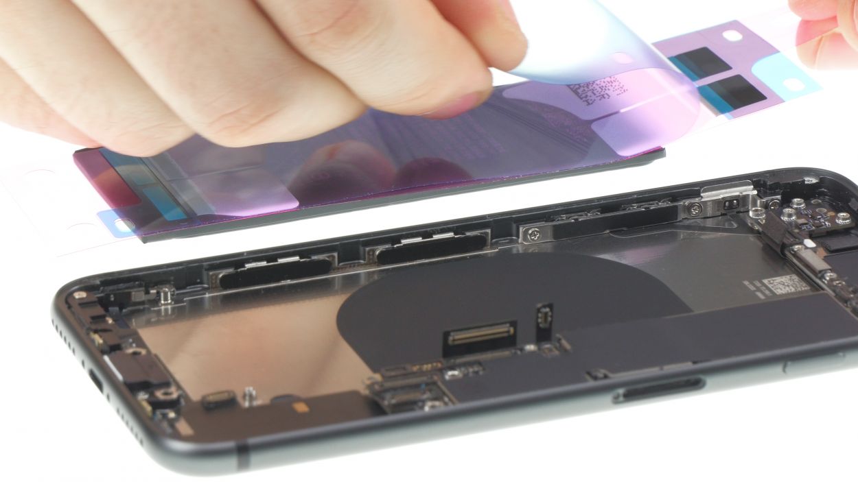

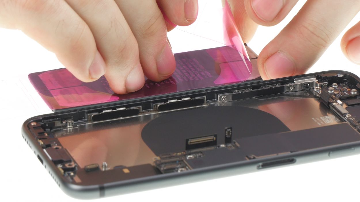
The adhesive strips must be aligned correctly. Check the alignment by placing the adhesive strips in your device first.
When attaching the tape, leave enough space on both sides to fold the tabs over.
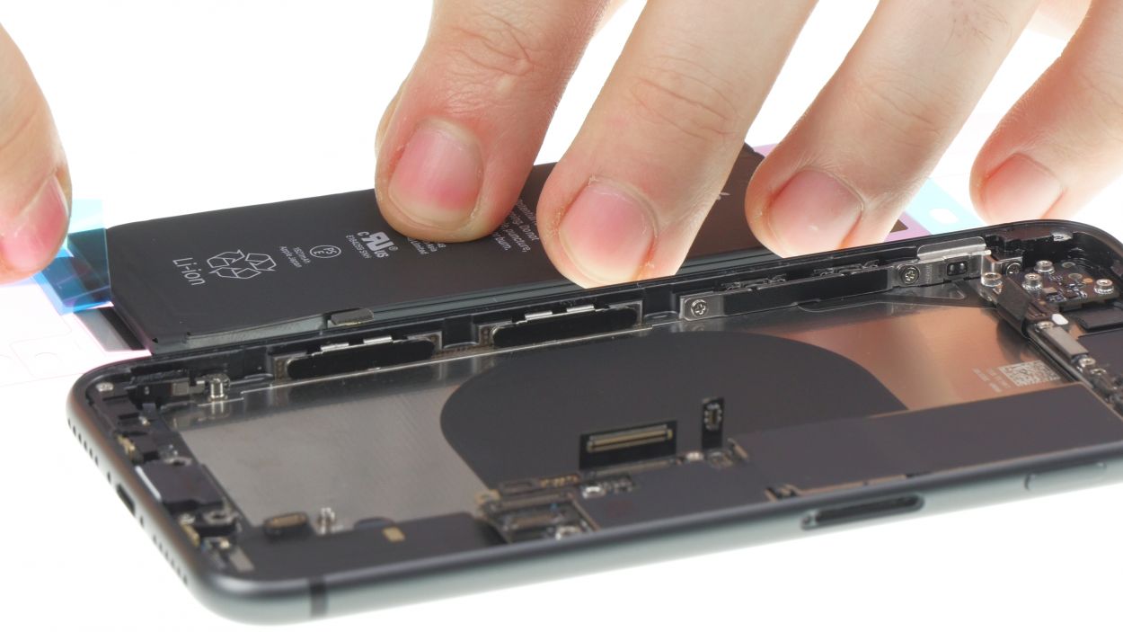
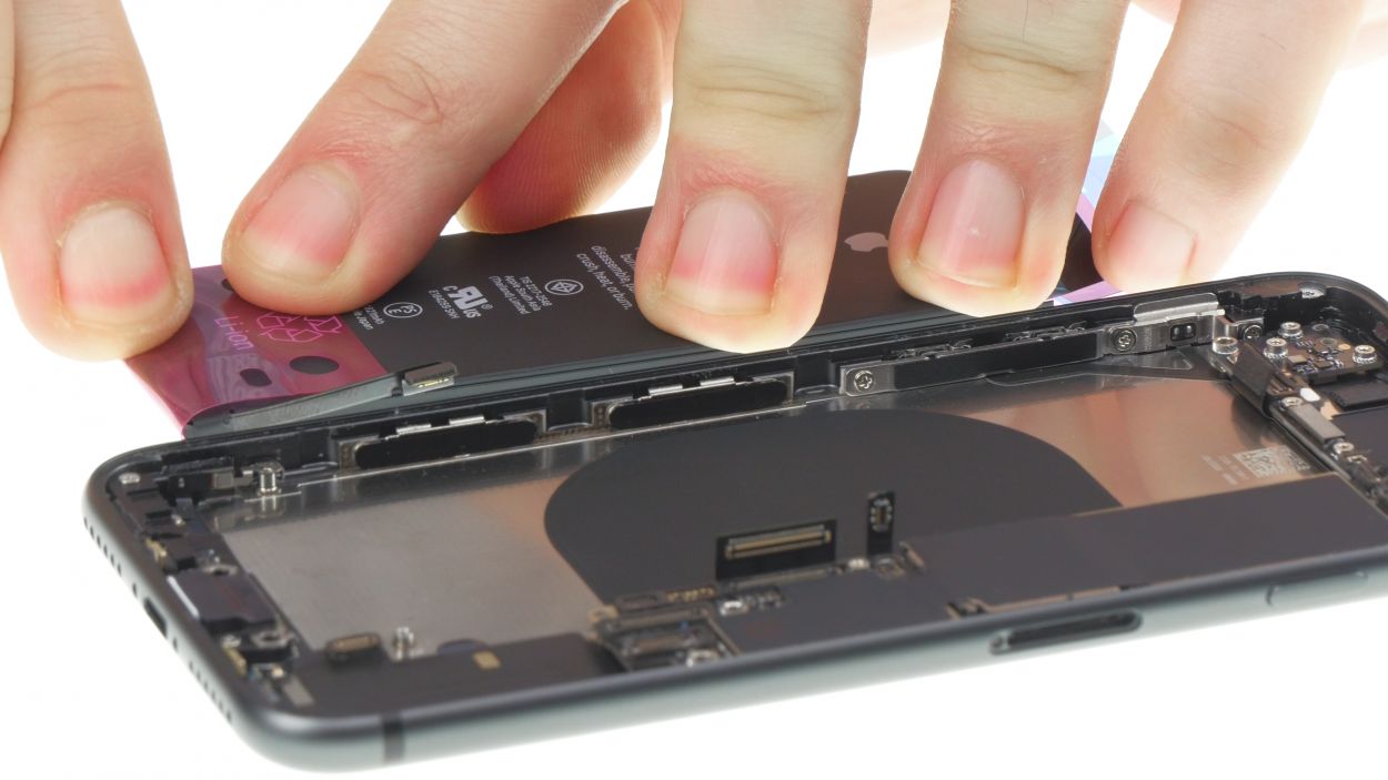
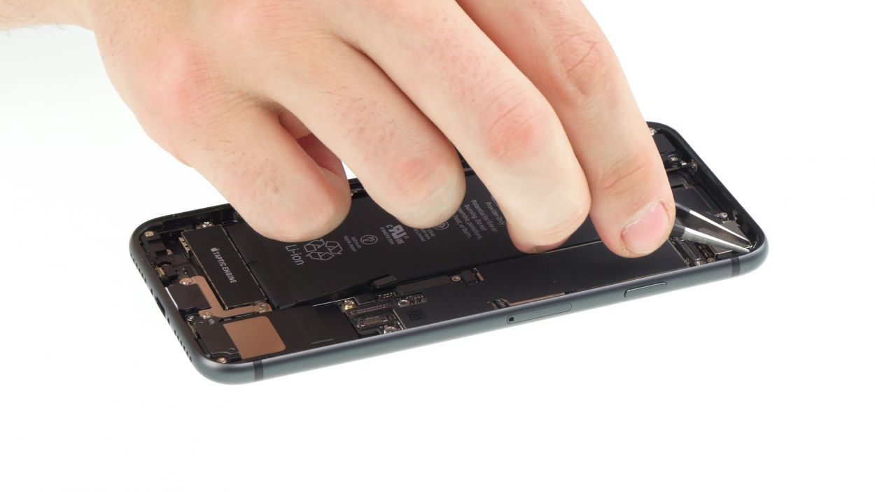
– First remove the blue protective film from the adhesive strips before placing them in the middle of the battery’s bottom side.
– Turn the battery over and remove the small blue and pink protective films from the tabs of the adhesive strips.
– Fold the tabs over to attach them to the top side of the battery.
Tools Used
Step 36
1 × 2.0 mm Standoff
1 × 2.0 mm Phillips
Make sure the screw holes of the Taptic Engine sit correctly, in order to avoid damaging the screws.
– Put the Taptic Engine back between the battery and the Lightning connector.
Step 37

1 × 2.1 mm Phillips
1 × 1.4 mm Phillips
1 × 1.2 mm Y-type
1 × 2.9 mm Phillips
1 × 2.5 mm Phillips
Make sure to correctly position the flex cable between the battery and the speaker
– Place the speaker back in its original position in the rear case and press it down.
– Now you can fasten the speaker using the two Phillips-screws.
– Press in the connector of the speaker.
– Reinsert the bracket plate over the flex cable and fasten it using the three screws.
Step 38
1 × 2.4 mm Standoff
1 × 2.1 mm Standoff
1 × 1.6 mm Phillips
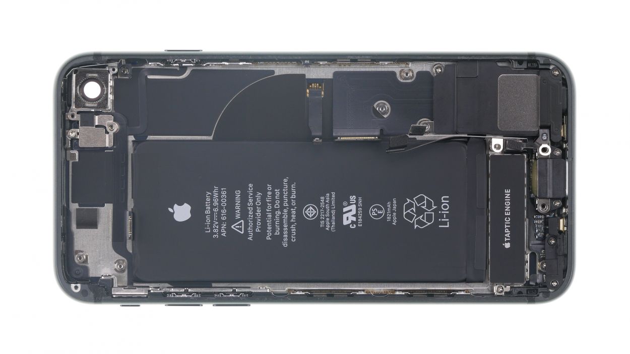
The camera holder should be on top of the logicboard (over the screw hole on the top right in the image).
– Reinsert the logicboard in its original position.
Step 39
– First position the connectors over their sockets and then carefully press them in with your finger.
Step 40
If you’re having trouble sliding it in, check the position of the logicboard.
– Now insert the SIM card tray into its slot.
Step 41

1 × 1.3 mm Phillips
1 × 1.2 mm Phillips
– Put the Wi-Fi antenna back in its original position and gently press it on to restore the adhesion.
– Connect the antenna’s connector.
– Then, attach the bracket plate with the two Phillips-screws.
Step 42
1 × 2.5 mm Phillips
1 × 1.4 mm Phillips
2 × 1.2 mm Phillips
2 × 1.0 mm Phillips
– Put the connecting piece back into its position and fasten it with the Phillips-screws.
– Now reinstall the plastic bracket and fasten it with Phillips-screws as well.
Step 43
1 × 1.1 mm Phillips
1 × 2.7 mm Phillips
– Attach the connector of the volume control cable again.
– Put the bracket plate back on the connector and fasten it with the screws.
Step 44
1 × 2.9 mm Phillips
1 × 3.0 mm Standoff
– Press the camera back into its opening.
– Attach the camera connector.
– Put the bracket plate of the camera back on and screw it tight.
Step 45
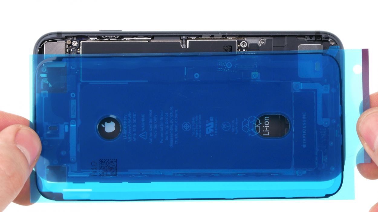
After attaching a new adhesive frame, iPhone 8 is again protected against dust and splash water, but is no longer 100% waterproof.
The corners are different and help with orientation.
– First remove all adhesive residue on the metal frame and display to ensure that the new adhesive frame fits properly.
– Try to align the adhesive frame with the back cover of your iPhone in order to position it correctly.
Tools Used
Step 48
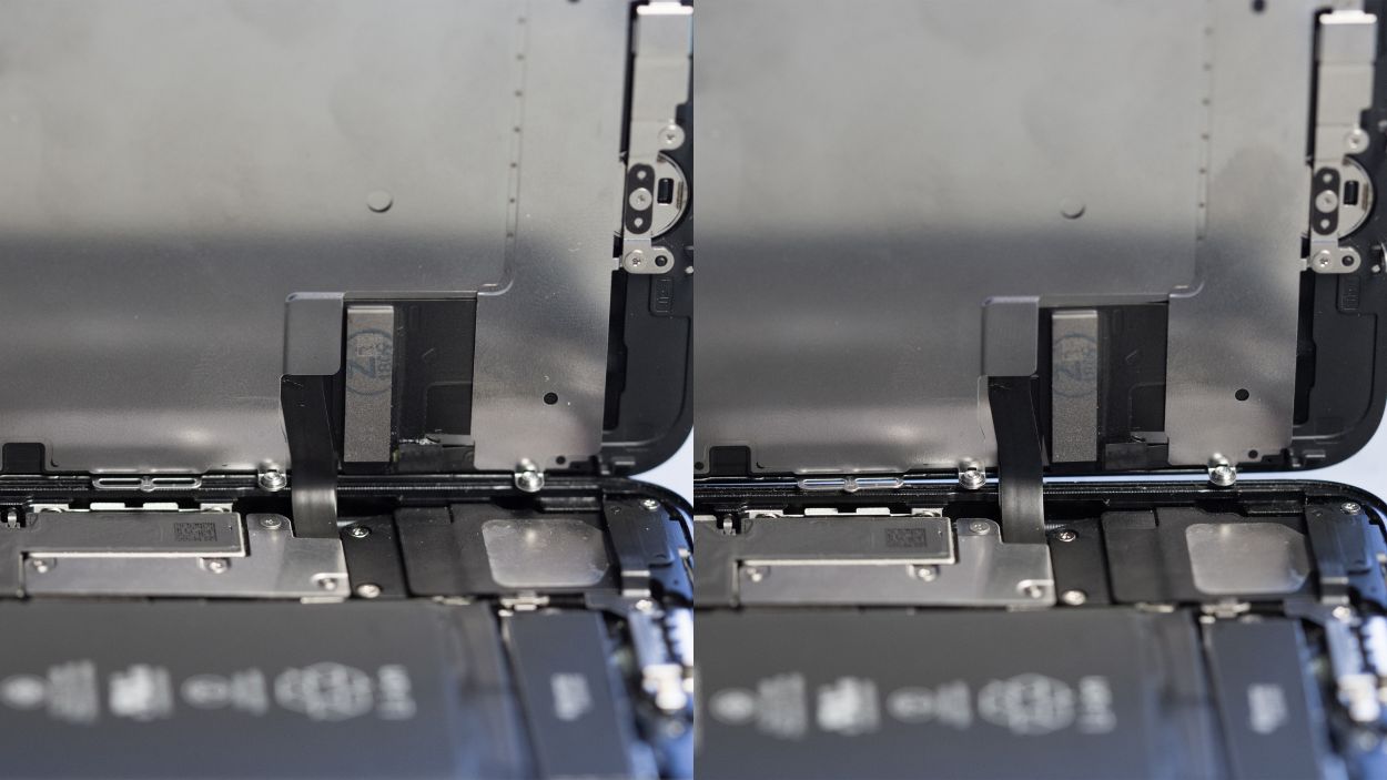
Wrong position
Right position
Make sure that the silver chip on the cable is positioned exactly as before (see photo). Otherwise, you will see discolorations and spots on the screen at this exact spot after installation. If you notice this error, check the position of the cable again and align the chip exactly like in our photo.
– Place the display on the side of the back cover and carefully fold it over.
– Then press the display firmly over the entire surface.

Step 50
2 × 3.4 mm Pentalobe
– Screw the two pentalobe screws left and right of the Lightning connector back into the rear case.
Tools Used