
Step-by-Step MacBook Pro 15 Antenna Replacement Guide
Duration: 45 minutes
Steps: 36 Steps
Hey there! Just a friendly reminder to take your time and follow each step carefully. If you hit a snag or need a hand, don’t hesitate to reach out and schedule a repair. You’ve got this!
Follow this guide to swap out those faulty antenna cables without the hassle of replacing your whole display.
Step 2

– Unscrew the trio of twin Phillips screws holding the memory door in place. Let’s get those screws out and move one step closer to victory!
Step 3

– Give that memory door a gentle lift to grab it, then slide it toward yourself and away from the casing like you’re pulling a rabbit out of a hat!
Step 4

– Whip out your screwdriver and zestfully remove the two 2.8 mm Phillips screws chilling near the latch in the battery compartment.
Step 5

– Pop out the following 6 screws:
Step 6

– Unscrew the four 3.2 mm Phillips screws located on the port side of your computer and get ready for the next step!
Step 7

– Give your computer a little twirl, spinning it 90 degrees. Next, zap away those two 3.2 mm Phillips screws hanging out on the back of your computer.
Step 8

– Spin the computer around once more and unscrew the four 3.2 mm Phillips screws from the side of the computer.
Step 9

Take it easy when removing the upper case! It’s connected to the logic board with a ribbon cable, so give it a gentle touch.
– Start by gently lifting the back of the case and let your fingers dance along the sides, releasing the case as you go. Once the sides are free, give the case a little wiggle up and down to loosen the front of the upper case—there are some sneaky plastic clips that need a little nudge to pop off. If you need help, you can always schedule a repair!
Step 10

– Unplug the trackpad and keyboard ribbon cable from the logic board, peeling off any tape as needed.
– Take off the upper case.
Step 11

– Unhook the trio of antenna cables attached to the Airport Extreme card.
– Apple thoughtfully labeled where each colored antenna cable goes – just make sure to check it out when reconnecting the antenna cables. If you need help, you can always schedule a repair.
Step 12

– Gently guide the Airport antenna cables out of their cozy little channel in the left speaker.
Step 13

– Gently slide the iSight cable to the left and pop it out of the logic board connector. You’re doing great!
Step 14

– Gently detach the inverter cable from the logic board by sliding a spudger underneath and giving it a little lift. You’ve got this!
Tools Used


Step 16

– Unscrew the shiny silver T6 Torx that’s holding the ground loop between the display data cable and the casing.
Step 17

– While keeping a firm grip on the display, give a little love tap to release these 3 screws:
Step 18

– Hold onto the display assembly with both hands and gently lift it up and away from the computer. You’ve got this!
Step 19


– Take out the two 5 mm Phillips screws from the bottom left and right corners of the display (total of two screws).
Step 20


– Slide the flat end of your trusty spudger right between the plastic strip on the rear bezel and the front bezel, keeping it perpendicular to the display. You’ve got this!
– With that spudger snugly in place, give it a gentle twist away from the display to start the separation of the front and rear bezels. Easy peasy!
– Keep working your way along the left edge of the display until the rear bezel pops free from the front bezel. Just like that, you’re on your way!
Tools Used


Step 22


– Gently slide the flat end of a spudger between the front bezel and the plastic strip attached to the rear bezel near the screw holes at the bottom corners of the display.
– With a smooth motion, pivot your spudger towards the rear bezel to gently separate it from the front bezel.
– If needed, make the gap between the lower edge of the rear bezel and the clutch cover a bit wider until the two parts come apart effortlessly.
Tools Used

Step 24

The display inverter is a super slim and sensitive circuit board, so treat it like the delicate gem it is! Handle with care to keep it safe.
– Gently wiggle out the inverter board from the clutch cover.
Step 25

– Time to give that LCD backlight a little space! Disconnect it from the inverter by gently pulling its connector away from the inverter board.
Step 26

Hey there! Just a friendly reminder to treat that inverter cable ground loop with care—it’s a super thin and delicate wire, so let’s avoid any unnecessary strain on it. You’ve got this!
– Gently unplug the inverter cable by pulling its connector away from the inverter socket. You’ve got this!
Step 27


– Let’s kick things off by gently removing those pesky pieces of yellow kapton tape from the bottom left corner of your display. You got this!
– Next up, peel away the three green antenna ground straps from the copper tape along the bottom edge of the LCD. It’s like unwrapping a little gift!
– Finally, take off the piece of tape that’s holding the camera cable snug against the LCD. You’re almost there!
Step 28


– Gently take off the pieces of tape that are keeping the display data cable and camera cable connectors under wraps.
– Carefully peel away the camera cable from the foam tape at the top edge of the LCD. You’re doing great!
Step 29


– Gently ease the camera cable out of its socket on the camera board.
– Carefully disconnect the display data cable connector from its socket on the LCD.
– Pull both cables in a smooth, steady motion alongside the logic board.
Step 30


– Got a Core Duo machine? Check out picture 1 and gently unscrew those three Phillips screws that are holding the clutch assembly snugly to the lower edge of the front display bezel, right by the display data cable.
– If you’re rocking a Core 2 Duo Model A1211, take a peek at picture 2 and carefully remove those two Phillips screws that connect the clutch assembly to the lower edge of the front display bezel near the display data cable.
Step 31

– Let’s get started by unscrewing the tiny Phillips screw lurking behind the display data cable. It’s like finding a hidden treasure!
– Next up, slide that small rectangular steel bracket away from the right clutch hinge. It’s a little like a dance move, just smooth and easy!

Step 33


If you find it necessary, go ahead and give the right side of the clutch assembly some love by repeating this process.
Step 34

– Take out the five tiny Phillips screws that are keeping the plastic antenna cover snug inside the clutch cover. If you need help, you can always schedule a repair
Step 35

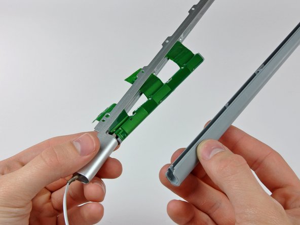
– Gently lift the antenna cover off the clutch cover, taking care not to harm those delicate antenna cables.
Step 36

– Gently detach the antenna cables from the clutch cover, being careful not to snag the connectors on the cover. If you need help, you can always schedule a repair.

