Step-by-Step Nintendo Switch Screen Replacement Guide
Duration: 45 minutes
Steps: 39 Steps
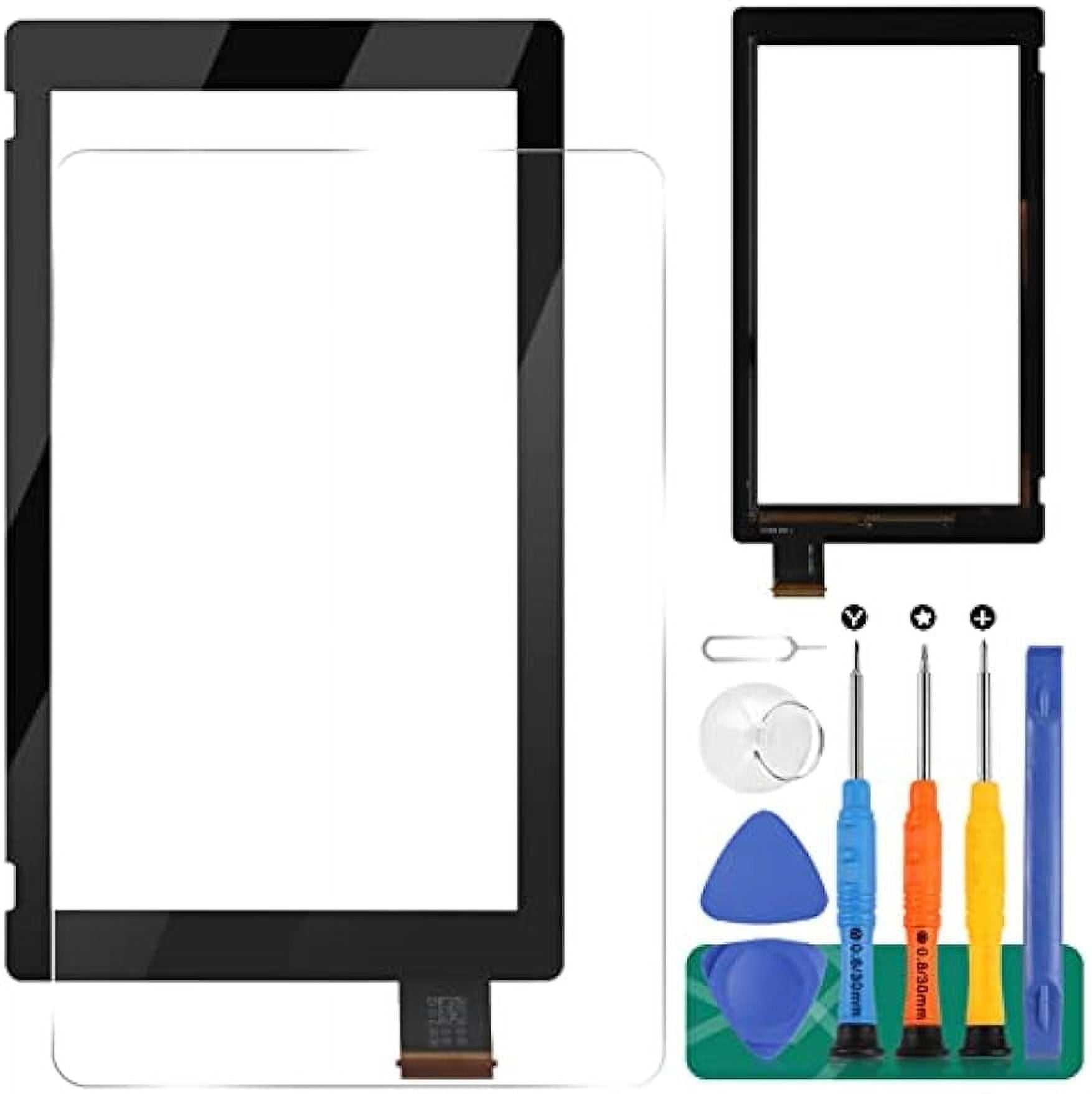
We’re swapping out the entire LCD panel and digitizer together like a dynamic duo!
Ready to tackle a screen replacement for your Nintendo Switch? Let’s do this! You’ll be swapping out both the LCD panel and digitizer as one complete unit. Want to replace just the digitizer? There’s a guide for that. Need only the LCD panel replaced? Yup, there’s a guide for that too. The Switch uses JIS screws, but a Phillips screwdriver can step in if needed—just be careful not to strip those screws! Pro tip: Phillips bits designed to work with JIS-style screws can be a lifesaver here. Heads up: When removing the shield plate, don’t forget to replace the thermal compound between it and the heatsink. Standard thermal paste won’t cut it for larger gaps, so go for a viscous thermal paste like K5 Pro. You’ll also need regular thermal paste for the CPU. While it’s possible to complete this repair without removing the heat sink and game card reader, it’ll make handling the LCD panel ribbon cable a bit trickier. Something to keep in mind as you work. Oh, and this guide (and the parts we recommend) are perfect for both the original 2017 Nintendo Switch model and the 2019 refreshed version (model numbers HAC-001 and HAC-001(-01)). Let’s get started!
Step 1


Before diving into this repair adventure, double-check that your device is totally powered down. Safety first, tech hero!
– Give that little round button on the back of your Joy Con controller a good press and hold, just like you’re about to make a wish!
– While you’re holding down that button, smoothly slide the controller upwards like you’re raising the roof!
Step 2


Now, give the other Joy-Con the same love and attention by repeating this process.
– Keep sliding that Joy Con up until it pops right off the console, just like magic!
Step 3

As you work through this guide, make sure to keep track of each screw and return it to its original spot.
– Grab your Y00 screwdriver and pop out the four 6.3mm screws holding down the rear panel.
Step 4


Don’t let those tight screws grind your gears! Apply firm downward force, take it slow, and if the screws don’t budge, switch to another JIS 000 or PH 000 driver. If you need help, you can always schedule a repair.
– Grab your trusty JIS 000 driver or the official iFixit PH 000 driver and let’s get those screws out! We’re looking to remove the screws holding the rear panel in place:
– One little 2.5 mm-long screw hanging out on the top edge of the device
– Two more 2.5 mm-long screws chilling on the bottom edge of the device
Step 5


– Let’s get started! Use a JIS 000 screwdriver or an official PH0000 driver to remove the two 3.8 mm center screws, one on each side of the device. This is the first step in giving your device a brand new life!
Step 6


Got a microSD card chilling in the slot? Go ahead and pop it out now before moving on to the next step.
– Gently pop out the kickstand on the back of the device using your finger—it’s like giving your device a little stretch break.
Step 7

– Grab your trusty JIS 000 screwdriver or the official iFixit PH 000 driver to tackle that 1.6 mm screw hiding in the kickstand well.
– Now, go ahead and close that kickstand like a pro!
Step 8


The game card flap is like a little guardian—it hooks onto the other half of the plastic shell, making it tricky to fully lift the rear panel if it’s shut tight.
– Pop open the game card cartridge flap.
– Gently lift the rear panel from the bottom of the device and remove it.
Step 9

– Grab your JIS 000 screwdriver or an official PH 000 driver, and get that 3.1 mm screw out to free the microSD card reader.
Step 10


– Gently grab the microSD card reader using your fingers or a pair of tweezers, and lift it straight up to disconnect and remove it from the device.
– When putting things back together, make sure the press connector hiding under the foam pad is securely plugged into the motherboard. If it’s being stubborn, peeling off the foam pad before reinstalling the card reader might do the trick.
Tools Used

Step 11

– Grab your trusty JIS 000 screwdriver or the official iFixit PH 000 driver, and let’s get to work! Carefully unscrew those six 3 mm screws holding the shield plate in place. You’ve got this!
Step 12


If the foam isn’t budging easily, just take a breath and don’t force it! We don’t want any tearing drama here. Gently try peeling from different angles to ease that foam back.
– Grab a pair of tweezers or just use your fingers to gently peel back the foam piece on the top edge of the device, right near the fan exhaust port. Easy does it—you’re doing great!
Tools Used
Step 13


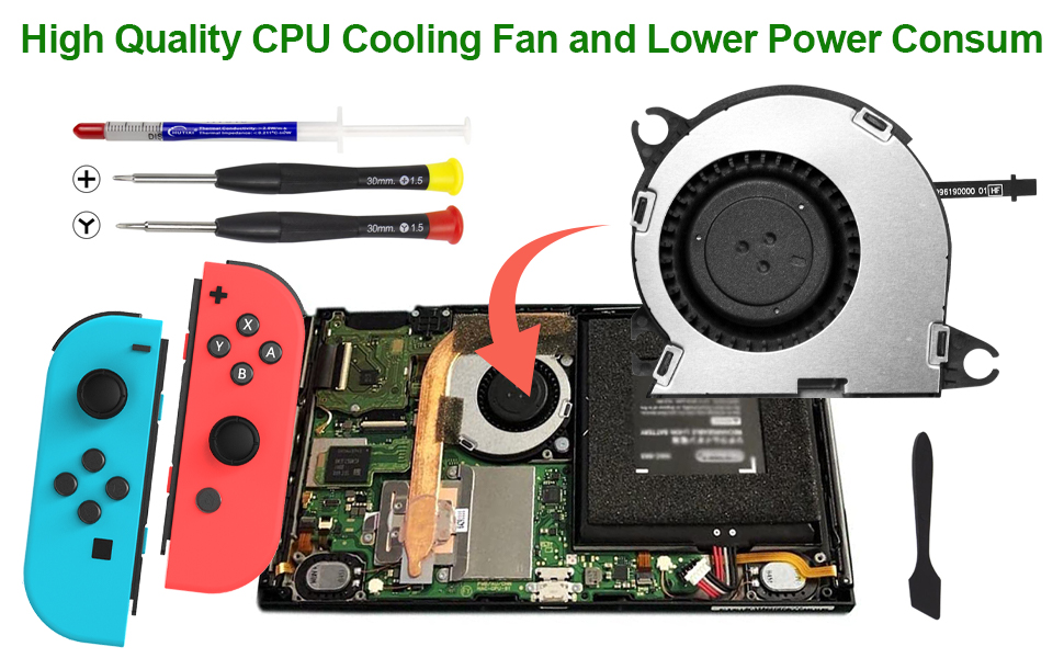
There’s a cozy layer of thick pink thermal compound snugly filling the space between the shield plate and the copper heat sink below. This little buddy works hard to keep your Switch nice and cool, preventing any overheating drama.
You might notice a bit of a tug when you try to separate the shield plate. No worries, that’s totally normal! The thermal paste has formed a slight bond with the heat sink, so just give it a gentle nudge.
– Gently slide a spudger under the shield plate along the edge—think of it as sneaking into the coolest party in town.
– Carefully pry upward to pop the shield plate off and set it aside like the VIP it is.
– If you’re feeling confident, you can reuse the pink thermal compound—just treat it like a precious gem. Keep it squeaky clean and make sure it snuggles up nicely between the heat sink and the shield when you’re putting everything back together.
– Need to replace it? No worries! Check out our thermal paste guide to clean off the old stuff and apply some fresh compound, like K5 Pro, during reassembly. Your device will thank you for the TLC!
Tools Used


Step 14


– Gently use the tip of a spudger to lift the battery connector straight up and out of its cozy spot on the motherboard. You’ve got this!
Tools Used
Step 15

– Grab your trusty JIS 000 screwdriver or a PH 000 driver, and unscrew the three 3 mm screws holding the heat sink snugly to the motherboard. Steady hands, you’ve got this!
Step 16
Be gentle! The foam is super delicate and can tear easily, so let’s get it off safely. Here’s the pro tip:
You just need to pull back the foam a bit until the fan is clear. No need to go overboard!
– Gently lift off the two foam pads hanging out on the heatsink and fan, but make sure you’re pulling them away from the fan itself—easy does it!
– Take your trusty spudger and slide its point under the foam where it’s loose and not sticking to anything.
– Use your finger to press down on the foam, keeping it steady while you work your magic.
– Now roll the spudger tip smoothly under the foam, gliding all the way to the other end to unstick it completely. Done and dusted!
Tools Used
Step 17


You might notice a little pushback here, and that’s totally cool! It’s just the heat sink giving a friendly hug to the CPU thanks to some thermal paste. No worries, you’re doing great!
– Gently pry up the heatsink from the motherboard using a spudger or your fingers. Once it’s free, remove it carefully.
– Grab some high-concentration (90% or higher) isopropyl alcohol and a microfiber cloth to clean off the old thermal paste from the heatsink and CPU. Don’t forget to apply fresh thermal paste to the CPU before putting things back together.
– Spread thermal paste on all the surfaces that had it before. That includes the space between the heatpipe and aluminum shield – this is the Switch’s secret extra cooling hack!
Tools Used

Step 18


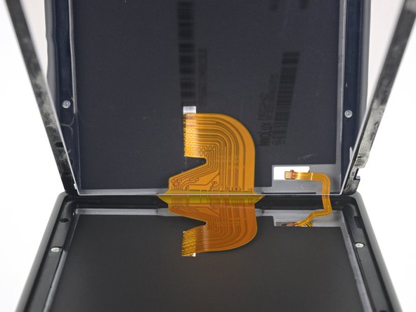
– Grab an opening tool or your trusty fingernail and gently flip up the tiny hinged locking flap on the digitizer cable’s ZIF connector. It’s like unlocking a mini treasure chest—easy does it!
Step 19


Hey there! Don’t try to jam that cable into the connector. If it’s not sliding in smoothly, just make sure the locking flap is flipped up, adjust the cable a bit, and give it another go. You’ve got this!
If your touchscreen is playing hard to get after the repair while your Game Card reader is still on point, double-check that this cable is snugly in place. But if the Game Card reader decides to join the touchscreen in its rebellious ways, take a peek at the Game Card connector in the next step.
– Grab a trusty pair of tweezers and gently slide that digitizer cable out of its cozy connector on the game card reader board—easy does it!
– Before you pop that cable back in during reassembly, make sure the ZIF connector locking flap is flipped up and ready to go.
– With the cable lined up parallel to the board, carefully slide it into its connector like a pro.
Tools Used
Step 20


If the touchscreen’s being stubborn or the game cards are ghosting you after reassembly, chances are that press connector didn’t get a proper handshake. Gently pop it off and reconnect it—easy does it!
– Grab your trusty spudger and gently work the tip underneath the headphone jack and game card reader connector. Give it a little lift straight up to disconnect it from the motherboard – you’ve got this!
– When it’s time to reconnect, align those connectors like a pro! Press down on one side until you hear that satisfying click, then do the same on the other side. Steer clear of pressing down in the middle, though! Misalignment can bend those pins and lead to a world of trouble. Remember, if you ever feel stuck, you can always schedule a repair.
Tools Used
Step 21

– Use a JIS 000 screwdriver or an official PH0000 driver to remove the three 3.1 mm screws that hold the headphone jack and game card reader board in place. Take your time and make sure you’ve got the right tool for the job – it’s gonna make this step a whole lot easier!
Step 22


– Grab a pair of tweezers or your fingers and carefully pop off the headphone jack bracket. It should come off with a little love and patience.
Tools Used
Step 23


– Grab a trusty pair of tweezers or just use your fingers to gently lift out the headphone jack and the game card reader board. Easy peasy!
Tools Used
Step 24


– Grab an opening tool, spudger, or just use your fingernail to gently flip up that tiny hinged locking flap on the LCD ribbon cable ZIF connector. Easy peasy!
Tools Used
Step 25


– Grab a trusty pair of tweezers and gently pull the ribbon cable straight out of its cozy connector on the motherboard. You’ve got this!
Tools Used
Step 26


– Grab your trusty opening tool, spudger, or even your fingernail, and gently lift that little hinged locking flap on the smaller LCD ribbon cable ZIF connector. You’ve got this!
Tools Used
Step 27


– Grab a trusty pair of tweezers and gently pull the ribbon cable straight out of its cozy connector on the motherboard. You’ve got this!
Tools Used
Step 28

Heads up! You can use a hair dryer, heat gun, or hot plate to get the job done, just be careful not to overheat things – your device’s display and internal battery are super sensitive to heat, so keep it cool!
– Warm up an iOpener and place it on the bottom edge of the screen for about two minutes to loosen up the adhesive.
Tools Used

Step 29


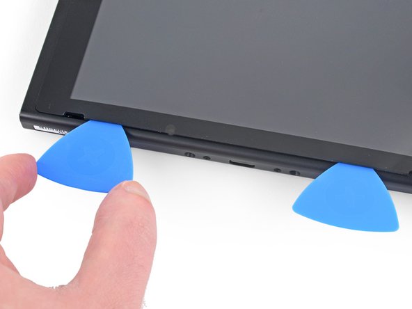
Depending on how long you’ve had your device, this might be a bit tricky. If you’re running into issues, just crank up the heat a little more and give it another go!
– Stick a suction cup onto the lower-left corner of the screen—give it a good press so it stays put.
– Pull up on that suction cup with steady, confident force until you see a tiny gap forming. You’ve got this!
– Gently slide the tip of an opening pick into the gap—go easy and keep it to about 5 mm to avoid any accidental oops moments.
Step 30


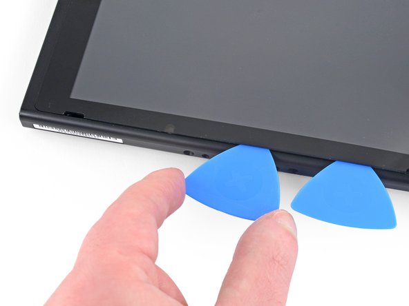
– Glide that opening pick smoothly along the bottom edge of the screen to cut through the adhesive—take your time, you’ve got this!
– Keep the pick in place to stop the adhesive from trying to stick itself back together—stay one step ahead!
Step 31

– Let’s get this device fixed! Insert a second opening pick into the gap, just to the left of the one you already have in place.
– Now it’s time to gently slide that new pick towards the left side of your device, taking care not to push too hard.
– Great job so far! Leave that pick inserted – you’ll need it for the next steps in your repair journey at Salvation Repair.
Step 32

– Warm up the left edge of the screen for about two minutes to loosen that adhesive and make your life a whole lot easier!
Step 33


– Keep gliding the opening pick around the bottom-left corner to gently slice through that sticky adhesive.
Step 34


– Glide that opening pick along the left edge of the screen and let it do its thing, slicing through the adhesive like butter.
Step 35

– Gently warm up the top edge of the screen for about two minutes to soften the adhesive. This will make things much easier when you start removing it.
Step 36


– Keep gliding that opening pick around the top-left corner of the screen to cut through the adhesive like a pro!
Step 37


– Keep gliding the opening pick along the top edge of the screen, slicing through the adhesive as you go. Stay steady, you’ve got this!
Step 38


– Warm up the right edge of the screen for about two minutes to loosen up that stubborn adhesive.
– Wedge the flat end of a spudger into the gap along the left edge of the screen.
– Gently and slowly lift the left edge of the screen—like you’re opening a book with fragile pages.
Tools Used
Step 39


Watch out for those ribbon cables! They’re sneaky and might get caught on the frame while you’re lifting the screen.
– Hold up your new part next to the old one—if they aren’t twins, you might need to move over some bits and peel off any sticky layers before popping it in.
– When you’re ready to reassemble, just rewind these steps like a movie in reverse—easy peasy!
– Got a funky screen after powering up? No biggie. Power down, unplug that battery connector, and hook it back up for a fresh start.
– Recycle your old parts responsibly—find an R2 or e-Stewards certified recycler to give them a second life.
– If things didn’t go as planned, don’t sweat it. Try some quick troubleshooting or swing by our Nintendo Switch Answers community for extra tips.
– Still stuck? No worries—Salvation Repair has your back. Schedule a repair anytime!
Success!