Xbox One X Disc Replacement Guide
Duration: 45 minutes
Steps: 35 Steps
Time to get handy! You’ll need to de-solder and solder two wires, but don’t worry, it’s doable with some patience and care. If you need help, you can always schedule a repair
Let’s get that Xbox One X disc drive spinning again! This guide will walk you through replacing the disc drive (aka the optical drive) on your Xbox One X model 1787. You might be here because other troubleshooting steps haven’t solved your disc-reading issues. Before we get started, be sure to power down the console and unplug any cables. Remember to follow general ESD (electrostatic discharge) safety guidelines while working on your console. Since the disc drive’s circuit board is connected to the console’s motherboard, we need to transfer the original board to the replacement disc drive. This means we’ll be doing a little de-soldering and soldering with two wires. No worries, it’s not as scary as it sounds. Just remember to wear eye protection, work in a well-ventilated area, and give your hands a good wash with soap and water after soldering. If you’re feeling a bit unsure, you can always schedule a repair.
Step 1


Before diving into this guide, make sure to power down your device and unplug any cables from the console. Let’s keep things safe and smooth sailing!
– Grab some blunt tweezers and gently peel back that sticker hiding the screw on the right side of the console. You’re doing great!
Step 2

– Grab your trusty T10 Torx screwdriver and get ready to work some magic! It’s time to unscrew those two screws, each measuring a neat 12.6 mm, that are hanging out on the back of the console. You’ve got this!
Step 3


– Twist the console 90 degrees to give yourself a better angle.
– Gently tug the front of the upper plastic case towards the console’s front. Keep going until it feels snug — this should help those pesky clips slide out of their cozy slots in the case.
Step 4


– Give that console a little spin! Rotate it 90 degrees so the back faces you.
– Now, grab the upper plastic case on the left side (lookin’ at the back) and lift it up. Stop when it feels like it’s gotta stop – that’s the limit, my friend.
Step 5


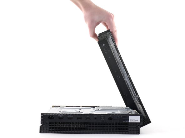
If pushing the case upwards isn’t doing the trick, give it a little shimmy in different directions until it swings open like it wants to be free!
– Keep your grip on the left side of the upper plastic case, and give a gentle push up on the right side to nudge that right-side screw boss out of the way.
– Now, swing the upper plastic case open to about 75 degrees. You’ve got this!
Step 6


– Gently nudge the top plastic cover down and away from the console, giving it a little wiggle to help release it completely.
Step 7


– Gently grab the pointed end of a spudger, an opening tool, or even your trusty fingernail. Give that small, hinged locking flap on the ribbon cable ZIF connector located on the front circuit board a little nudge to flip it down. You got this!
Tools Used

Step 8

– Grab some blunt tweezers and gently coax the ribbon cable downward, freeing it from the connector like a pro.
Step 9

– Let’s get started! Use a T8 Torx screwdriver to carefully remove the three 13.3 mm screws that hold the front circuit board in place inside the upper metal case. Take your time and make sure they’re all out before moving on to the next step.
Step 10


Hold onto the board with both hands near where it’s plugged in. We don’t want to bend it or hurt it, right?
– Gently slide the front circuit board straight out from the upper metal case and place it somewhere safe for now.
Step 11

– Grab your trusty T10 Torx screwdriver and tackle those six 47.7 mm screws holding the upper metal case snugly against the lower plastic case. You’ve got this!
– Next up, switch to a T8 Torx screwdriver to whisk away the two 7.5 mm screws that are keeping the press connector cozy with the upper metal case. Keep it going!
Step 12

Hey there! Just a friendly reminder: don’t push that spudger all the way to the socket. Lifting the socket too much might just cause some damage. Let’s keep everything safe and sound!
– Slide the flat end of your trusty spudger right under that press connector, making your way to the side that’s opposite the ribbon cable. You’ve got this!
– Now, give that spudger a little lift and gently nudge the press connector up and away from our friend, the upper metal case. Easy peasy!
– When it’s time to reattach those press connectors, just line them up carefully and give a gentle press down on one side until you hear that satisfying click! Then, repeat the process on the other side. Remember, no pressing in the middle—let’s keep those pins straight and avoid any mishaps that could lead to some permanent party crashing!
Tools Used
Step 13


Keep a grip on that lower plastic case, it’s about to become a free agent from the metal chassis!
– Let’s start by flipping the console over, shall we?
– Now, gently lift the lower plastic case away from the metal frame and set it aside like a pro.
Step 14

– Let’s get those two T10 Torx screws out so we can unveil the magic of the lower metal case:
– One screw measuring 7.7 mm
– One screw measuring 11.4 mm
Step 15

The disc drive might try to pop up along with the lower metal case. Make sure to give it a gentle press down while you tackle this step.
– Gently lift the lower metal case away from the upper metal case and the inner components—think of it as giving your device a little stretch!
– Once you’ve done that, set the lower metal case to the side like it’s taking a break while you continue your repair journey.
Step 16

Hey, the disc drive is just chilling on the motherboard with two little cables holding it down. When you flip things over, give it a little love and hold onto it so nothing gets hurt. We wouldn’t want to break the drive, now would we?
– Let’s get started by flipping the console over – it’s time to get hands-on!
– Now, grab your trusty T10 Torx screwdriver and carefully remove the two 11.4 mm screws that hold the power supply in place within the upper metal case.
Step 17


Hey there, Remember, the disc drive is wired to the motherboard. Just be sure to treat those wires with a bit of TLC so you don’t accidentally bend them too much!
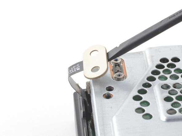
– Gently lift the disc drive to release its metal tab from the power supply—it’s like giving it a little nudge to let it know it’s time to move.
– Now, carefully place that disc drive on the upper metal case, positioning it right above the hard drive. Just make sure you’ve got enough room to unplug the power supply from the motherboard without a hitch!
Step 18

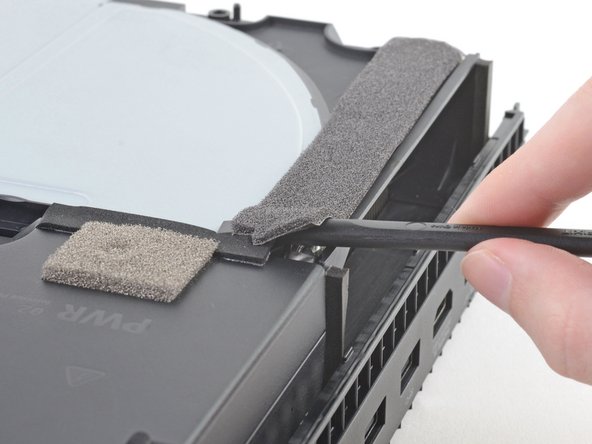
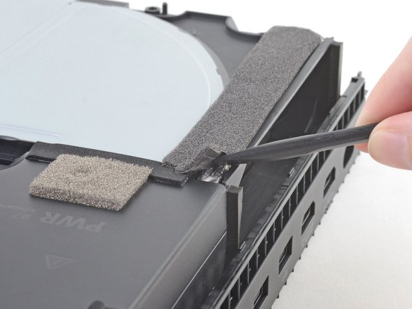
– Let’s start by gently sliding the flat end of your trusty spudger underneath that dark grey foam tape. Start at the corner closest to the power supply and the edge of the console.
– Now, lift up that corner like you’re giving it a little high five.
– Keep going! Slowly push the spudger along the tape until you see the flat end poking out on the other side. You’re doing great!
Tools Used
Step 19


If you need more room to work, you can always slide the disc drive a little further away from the power supply. No big deal, right? You got this!
– Gently lift the power supply straight up to disconnect it from the motherboard. You’ve got this!
Step 20


Those two grey cables are still hooked up to the console using that dark grey foam tape and the power supply socket under the fan case. Be careful not to bend them too much, you don’t want to hurt those little guys!
– Once you’ve safely unplugged the power supply from the motherboard, give it a little twist and gently lift it away from the console like a pro.
– Now, let’s set that power supply down on its side, just chillin’ right outside the upper metal case. You’ve got this!
Step 21
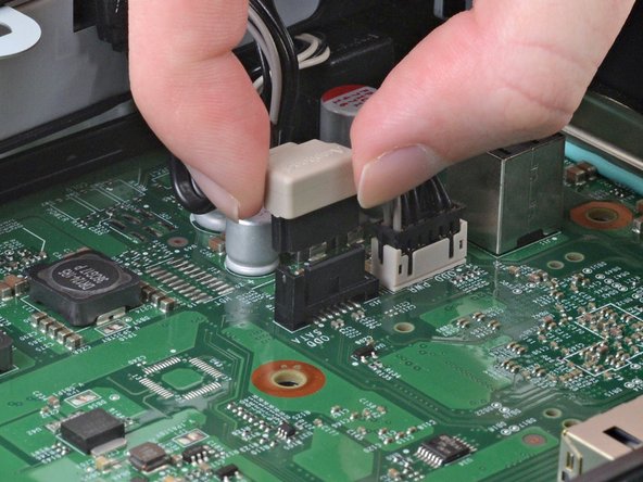

– Gently lift the SATA cable that connects the disc drive to the motherboard, pulling it straight up like you’re giving it a little friendly nudge!
Step 22
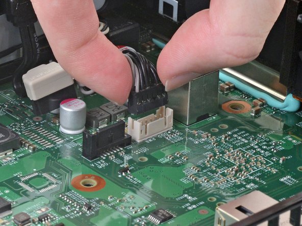

– Gently wiggle and pull the cable connector connecting the disc drive to the motherboard straight up to unplug it. You’ve got this!
Step 23

– Carefully pop that disc drive out of the console, like you’re unveiling a surprise gift! Easy does it!
Step 24


– Gently wiggle and slide that rubber vibration dampener right off the disc drive, just like taking off a cozy sock!
Step 25


– Give that bundled cable connector a little nudge and send it packing from the disc drive. It’s time to say goodbye!
Step 26
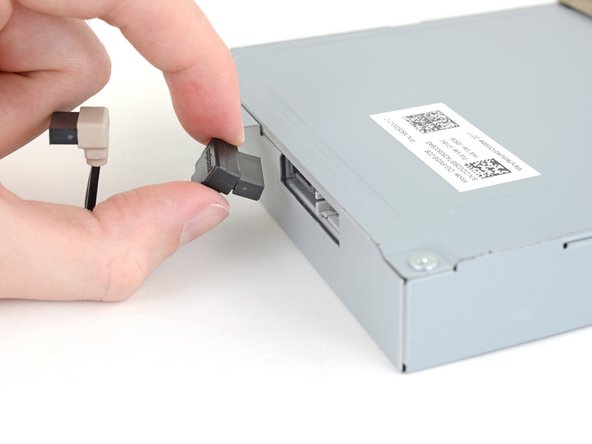

– Time to get started! Begin by carefully unplugging the SATA cable from the disc drive.
Step 27

No need to completely remove the foam covering the two right-side screws – just gently push it aside until the screws are exposed.
– Alright, time to get those screws out! Use your trusty Phillips screwdriver to loosen up those four 3.7 mm screws holding the disc drive cover in place. You got this!
Step 28

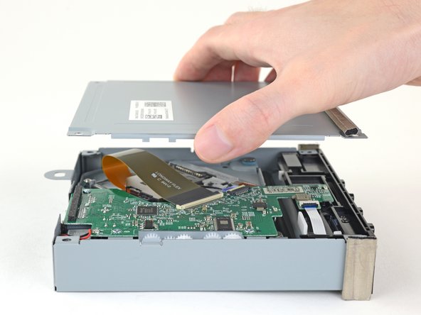
– Let’s get that disc drive cover off! Just gently pry it off and set it aside. It’s like taking off your favorite hat – no stress, just a smooth move.
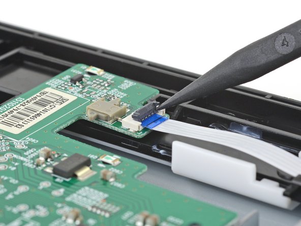
Step 29

– Now, it’s time to flip that little locking flap on the ribbon cable connector. You can use the tip of a spudger, an opening tool, or even your fingernail. It’s like giving the flap a little nudge to get it out of the way!
Tools Used
Step 30
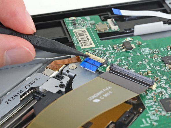

– Grab your trusty spudger, an opening tool, or even your nail, and gently lift that little hinged locking flap on the ribbon cable next to the larger one. You’re doing great!
Tools Used
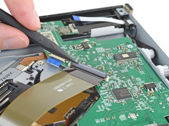
Step 31

– Use the tip of a spudger, an opening tool, or your fingernail to gently lift up the small, hinged locking flap on the long ribbon cable in the corner of the disc drive ZIF connector. It’s like giving that little flap a friendly nudge!
Tools Used
Step 32

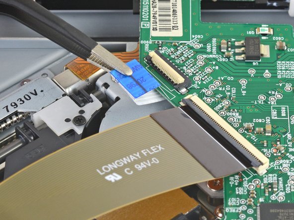

– Grab those blunt tweezers and gently tug on each of the three ribbon cables, pulling them out in the direction they’re heading. You’ve got this!
Step 33


Keep it safe and stylish with some soldering basics! Rock those safety glasses, find a breezy spot to work, and don’t forget to give your hands a good wash with soap and water after you’re done soldering.
Remember, too much heat can be a real party crasher for your electrical components! So, keep your soldering iron moving and don’t let it linger too long on the board.
– Grab that trusty soldering iron and gently desolder the red wire nestled in the corner of the disc drive circuit board. You’ve got this!
– Next up, give that adjacent black wire the same treatment. Use some blunt tweezers to carefully hold and pull those wires away from the circuit board like a pro.
– Now, when it’s time to pop the original circuit board back into the new disc drive, remember to solder the red wire to the pad marked ‘R’ and the black wire to the pad labeled ‘B.’ It’s a simple step that makes all the difference!
Step 34

– Grab your trusty Phillips screwdriver and tackle those three 3.4 mm screws holding the circuit board to the disc drive case. You’ve got this!
Step 35


– Now, to put your device back together, just retrace your steps like you’re going backward on a fun adventure!
– Got some e-waste? Take it to an R2 or e-Stewards certified recycler and give it a new lease on life!
– If things didn’t go quite right, no worries! Try some quick troubleshooting, or reach out to our Xbox One X Answers community for some friendly advice.
– If you need to, go ahead and cancel: I’m all good, thanks!
– You’re not alone—lots of others have tackled this guide too!
Success!
