iPhone 5 Rear Camera Replacement Guide: Step-by-Step Tutorial
Duration: 60 min.
Steps: 26 Steps
In this guide, we’re here to help you tackle the challenge of swapping out your iPhone 5’s rear camera, which might be throwing a fit! Whether your camera’s gone kaput, your photos are looking like they were taken through a foggy window, or it just refuses to focus, we’ve got your back. Follow along as we walk you through the steps to get that camera back in action. Let’s do this!
Step 1

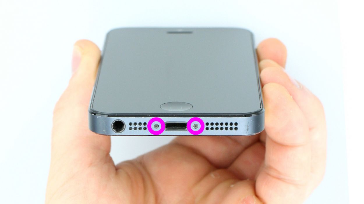
– Grab your trusty pentalobe screwdriver – it’s time to get that iPhone 5 open!
– Carefully take out the two pentalobe screws hanging out at the bottom of the enclosure. They’re chillin’ right next to the Lightning connector, one on each side. Make sure to toss those screws into the same compartment of your organizer tray so they don’t go wandering off! You’ve got 2 x 3.6 mm pentalobe screws to keep track of.
Step 2

– Set your iPhone 5 down on a soft, clean surface to keep that back from getting scratched. We want it looking sharp!
– To get that front panel lifted, grab a suction cup and a hard plastic pick. If your screen is looking a bit like a spider web, slap some packing tape over it for good measure.
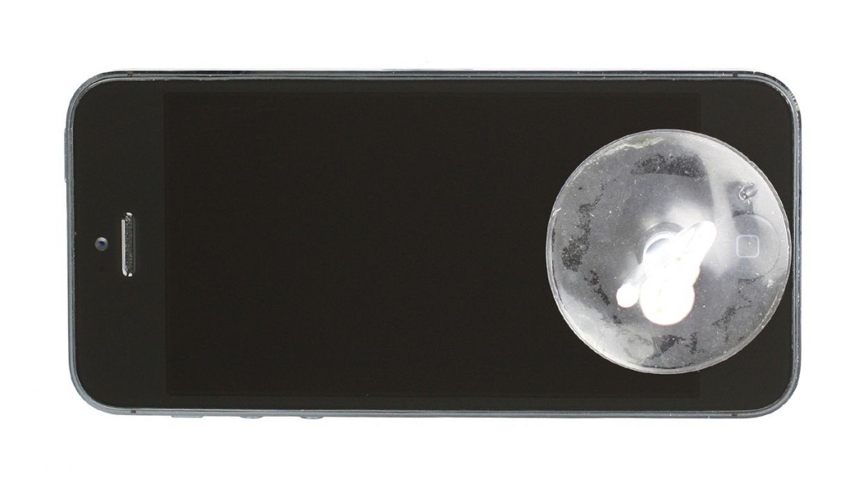
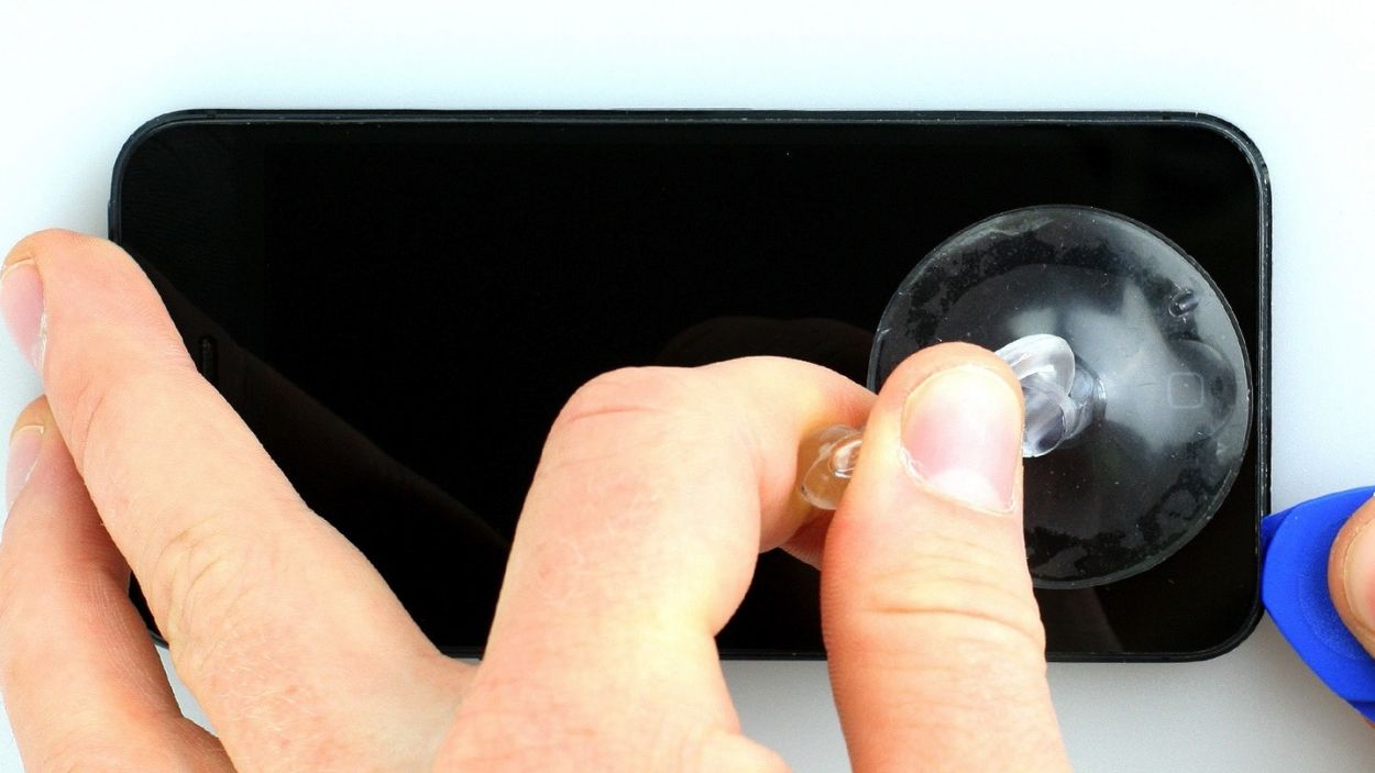
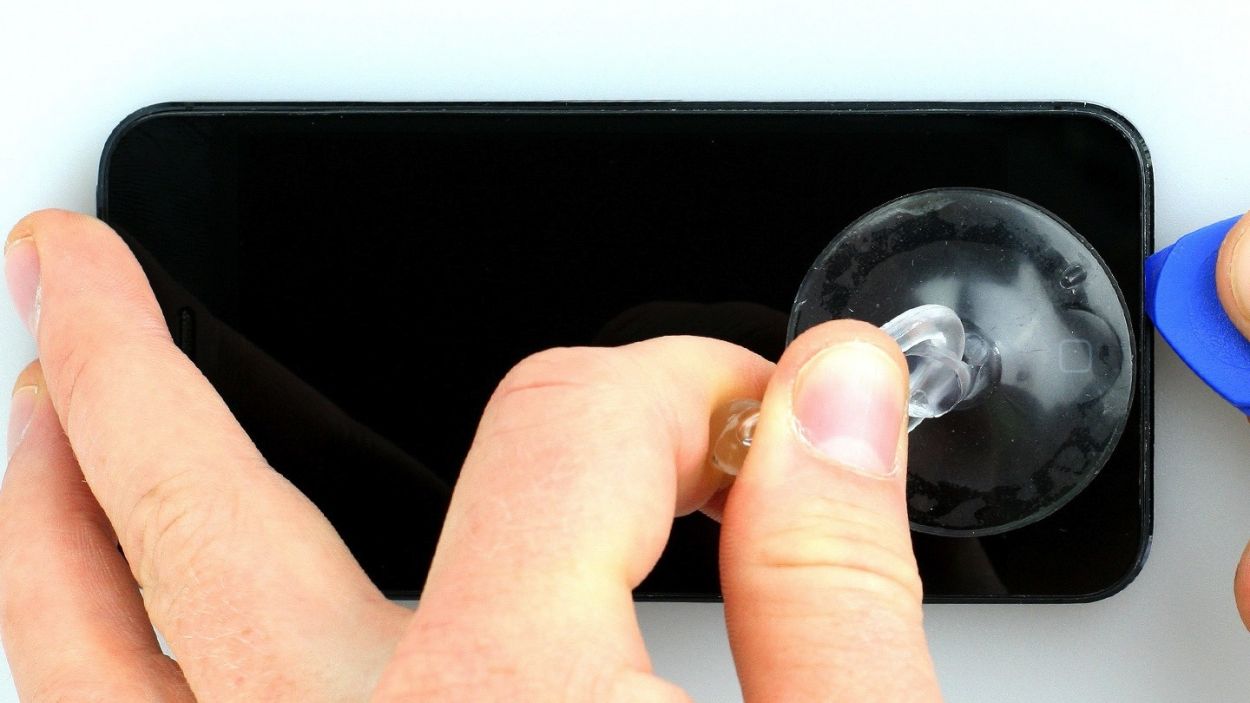
– Stick the suction cup over the Home button (if you can) or right next to it (check out figure 1). While you’re lifting the screen with the suction cup, slide the hard plastic pick between the aluminum frame and the display frame and gently push down on the aluminum frame. Use the pick to help lift the screen up (see figures 2 and 3). This might take a few tries, so don’t sweat it!
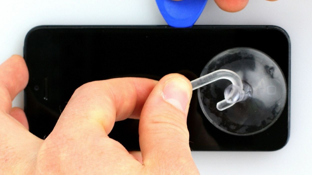
– Once you can lift the screen just a little (see figure 4), carefully work your way around the edges until it’s loosened up on both sides (see figure 5).
– When the display is completely free, you can flip it up from the Home button. Just a heads up, the display cables are still attached to the logic board (keep an eye out for the next step).
Step 3
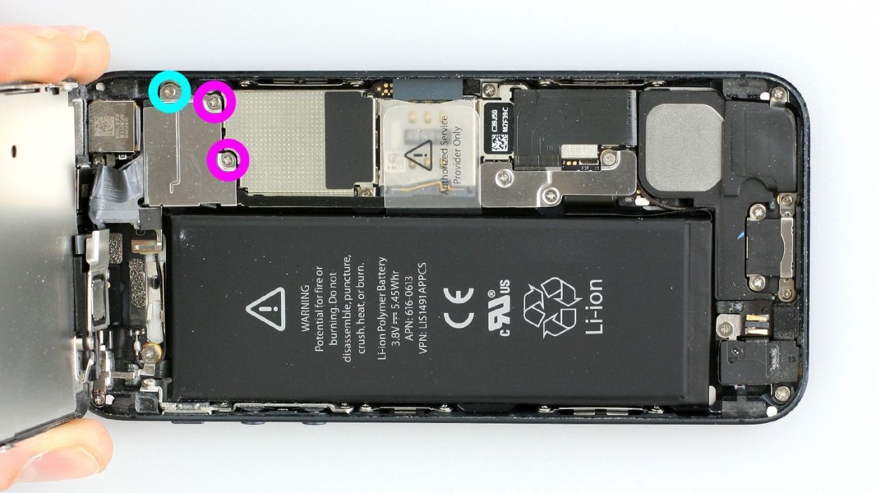

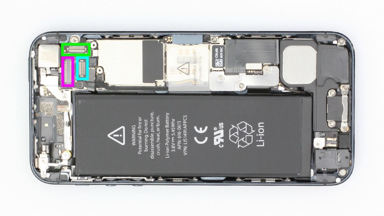
– First, let’s tackle those three Phillips screws holding the silver cover in place (check out figure 1). Pop those screws into the same little compartment of your organizer tray so they don’t go on an adventure! You’ll need to keep track of 2 x 1.2 mm Phillips screws and 1 x 1.7 mm Phillips screw (which is not magnetic).
– Next up, it’s time to disconnect the three connectors you see in figure 2. Just a friendly reminder to be super careful while doing this!
– Now grab your spudger and gently slide the pointed tip just below the contact, then give it a little lift. Be cautious not to break off those tiny resistors soldered onto the logic board. And hey, if you have a later model, those resistors might be protected by a black plastic film. We’re talking about the LCD, touchscreen, and front camera/sensor/earpiece here!
Step 4
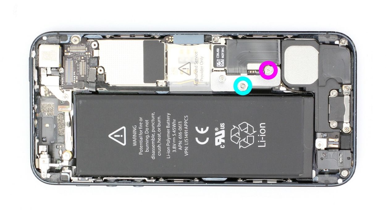
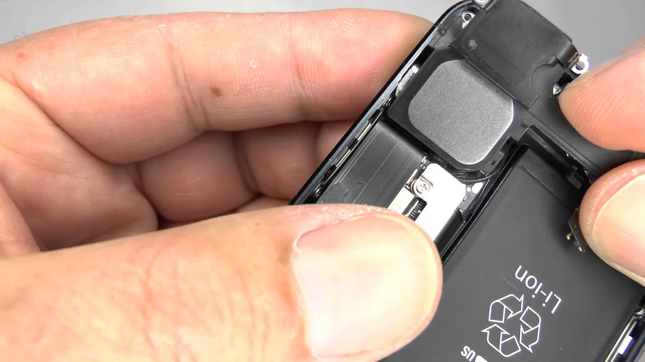
– Grab your Phillips screwdriver and let’s tackle those pesky screws holding the battery connector in place (check out figure 1 for reference). Once those are out, gently lift the cover using your trusty spudger (figure 2 is your guide). Remember to keep all those little parts cozy in the same compartment of your organizer tray. You’ll be dealing with 1 x 1.8 mm Phillips screw (funnel head) and 1 x 1.7 mm Phillips screw.
– Now, let’s delicately lift off that battery connector! Just slide the pointed tip of your ESD spudger right underneath the connector (figure 3 will show you where). If you find yourself without a spudger, your fingernail can step in as a substitute. Easy peasy!
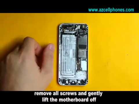
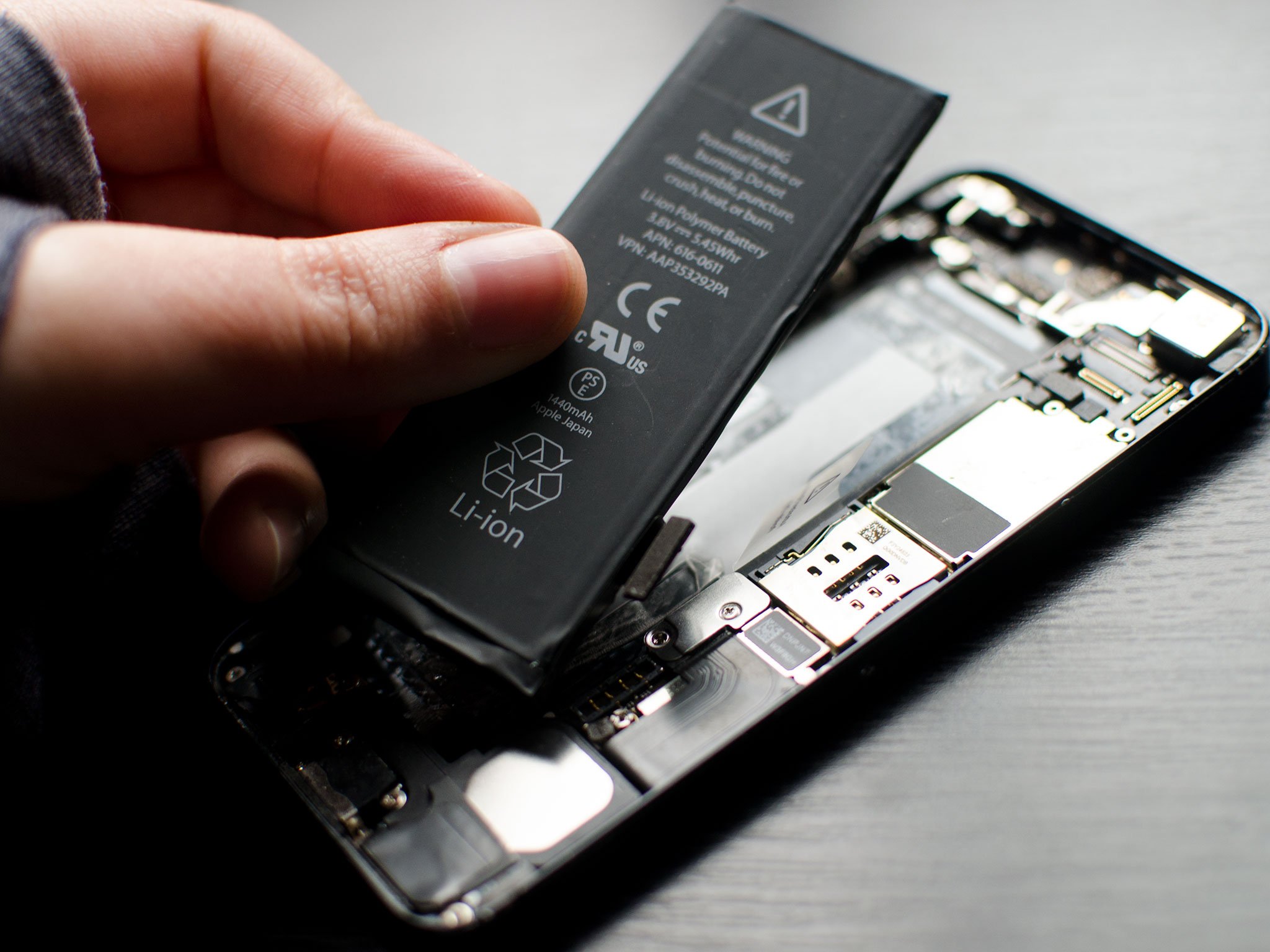
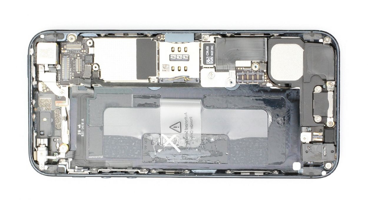
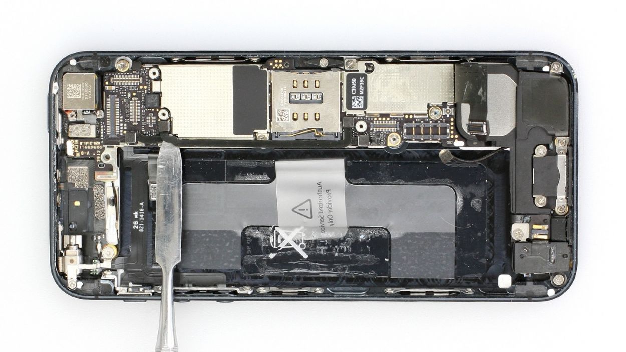
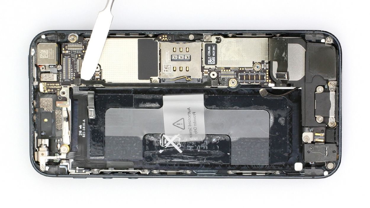
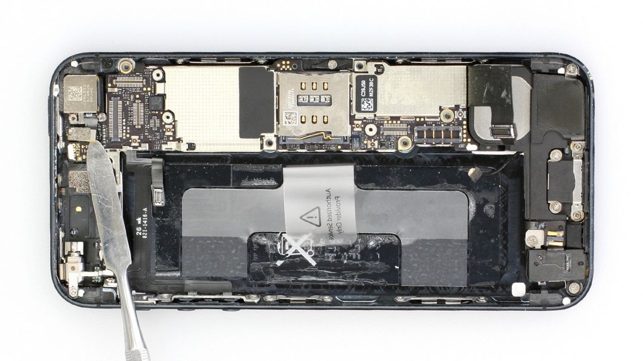
Step 5

The logic board is quite delicate, so handle it with care! You can also try lifting the battery from the opposite side if needed.
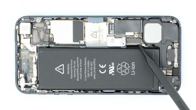
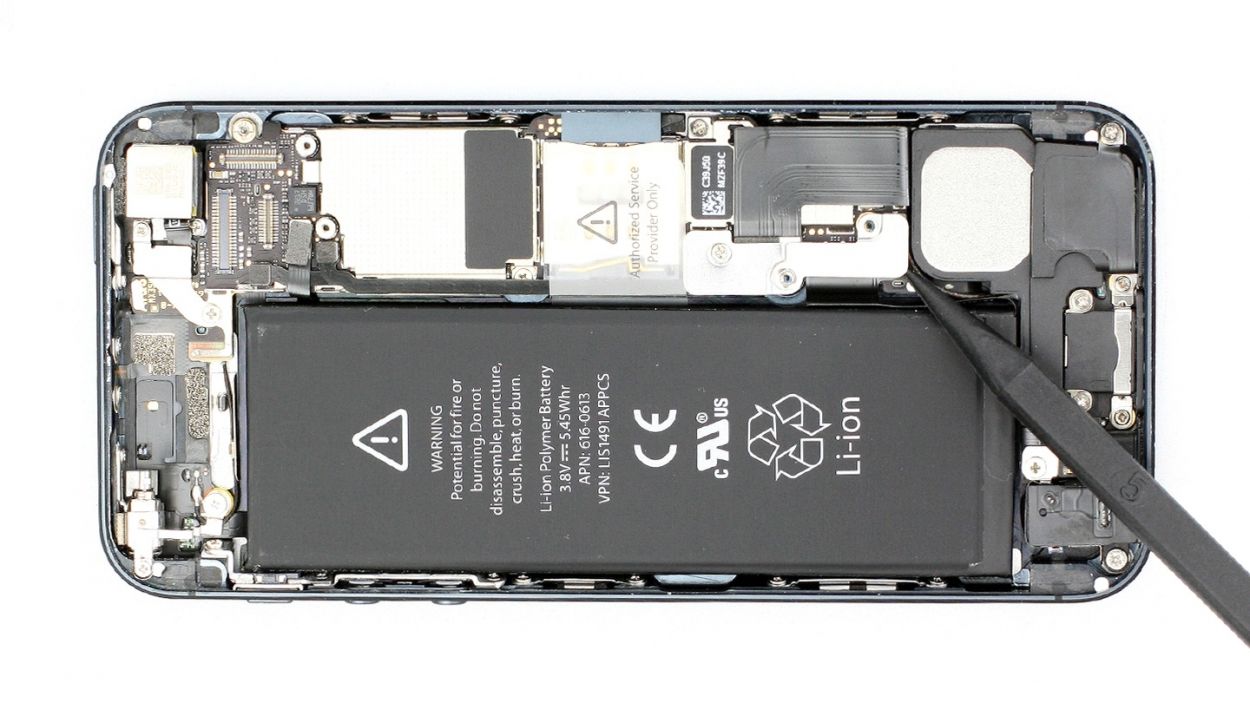
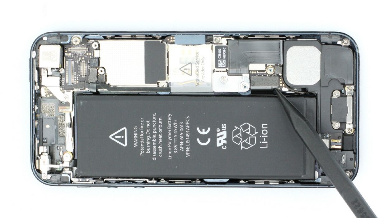
– Alright, it’s battery removal time! Sometimes it’s like that stubborn friend who just won’t budge. Grab your trusty spudger and slide the flat end into the gap between the battery and the logic board, then gently lift it out. Remember, the logic board is as delicate as a flower, so handle with care! If you need a little extra leverage, try lifting from the opposite side. If it’s still playing hard to get, use leverage points on either side to pry it loose. And if all else fails, a little warmth from a heat gun can help soften the glue and make things easier. You’ve got this!
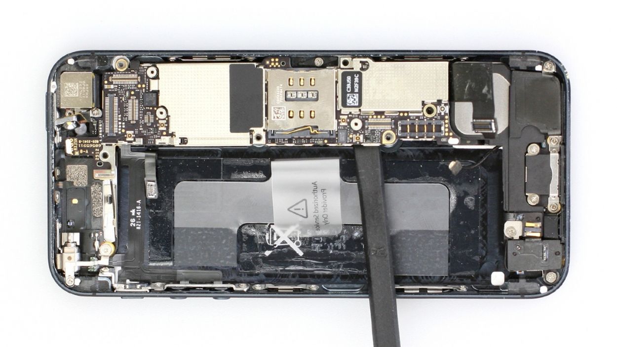
Step 6
– Fold the plastic tab with the warning over and press it down snugly onto the adhesive strip. This way, it won’t be a bother while you work your repair magic.
Step 7

– You can use the SIM Tool or a paperclip to remove the SIM card tray. Press the SIM Tool into the small hole in the SIM card tray to remove it.
Step 8
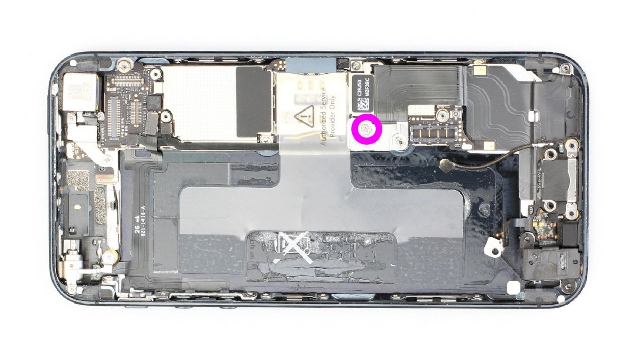
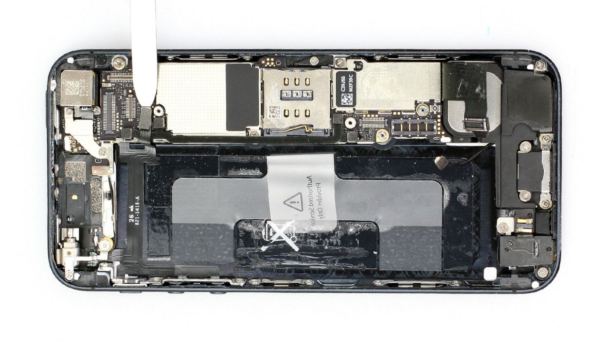
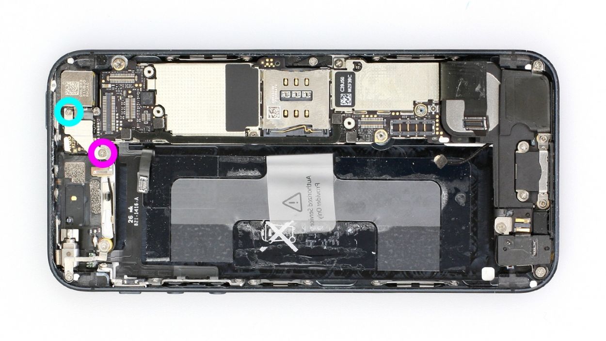
– First, let’s tackle that Phillips screw and the shiny silver cover hanging out below it (check out figure 1). Make sure to keep those parts cozy in the same compartment of your organizer tray – you’ve got a 1 x 1.2 mm Phillips screw to keep track of!
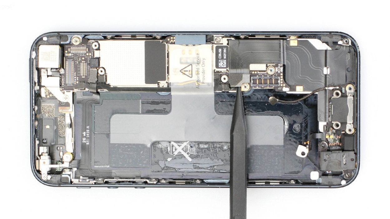
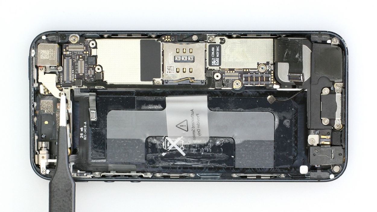
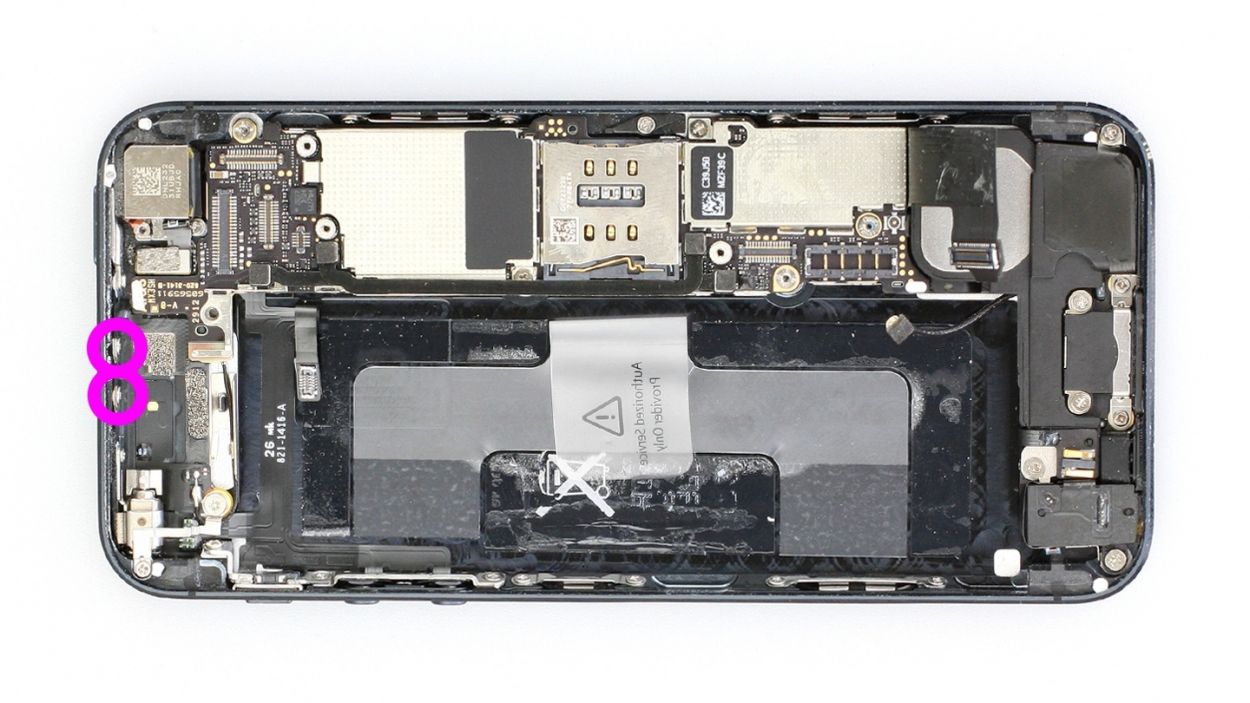
– Now, let’s disconnect the Lightning connector’s ribbon cable (see figure 2). Gently slide the pointed tip of your spudger just below the contact and give it a little lift. Once you’ve done that, carefully fold the cable over. Easy peasy!
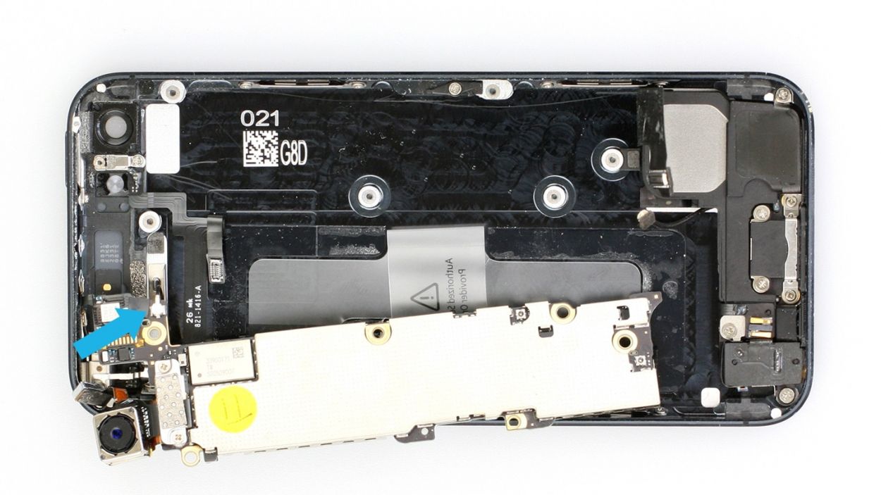
Step 9
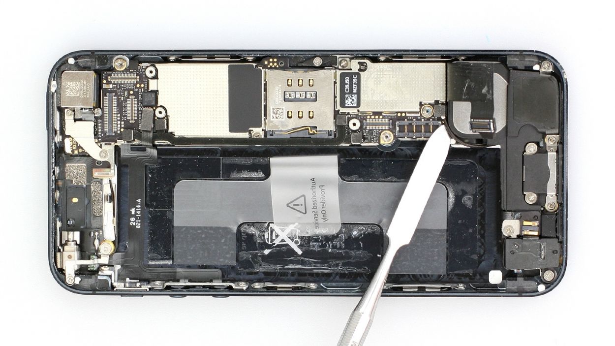
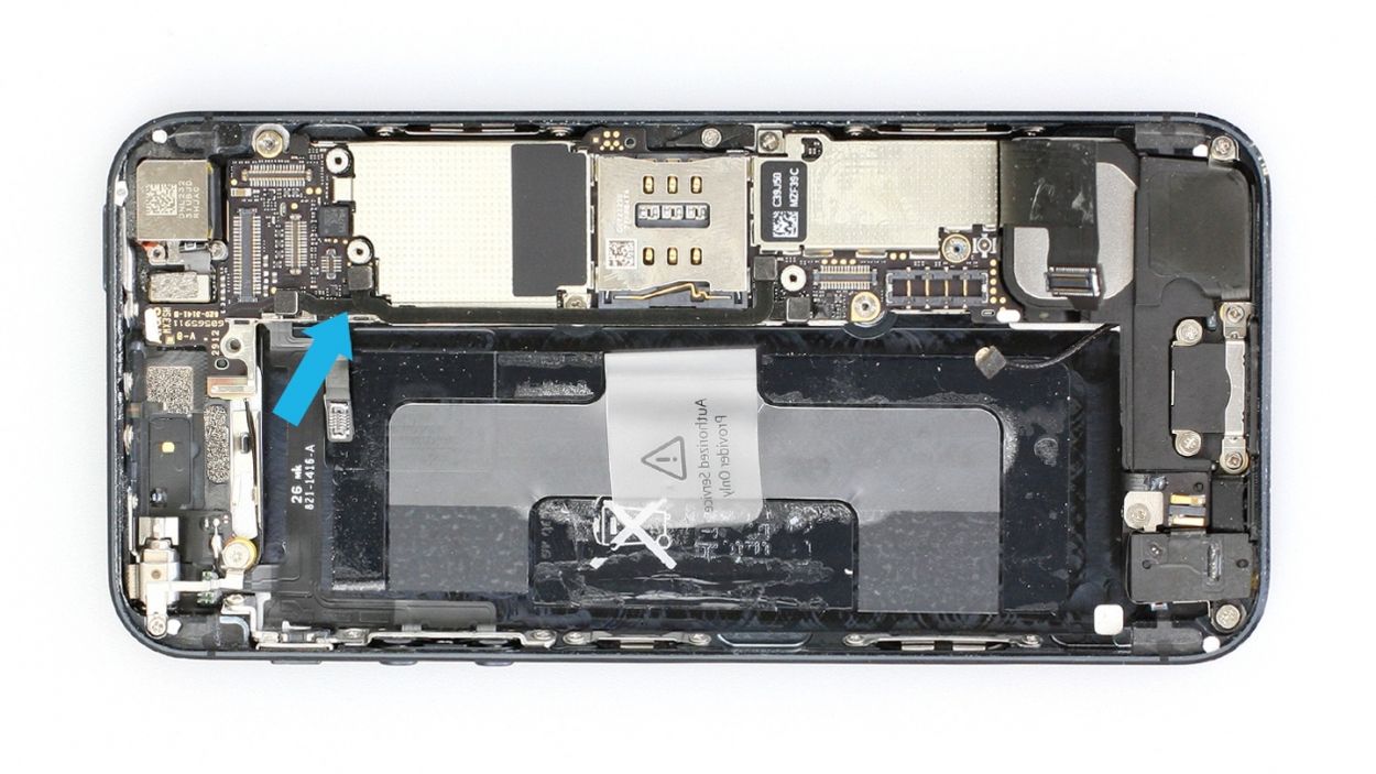
– Gently lift off the antenna connector using your lab spatula (check out figure 1 for reference).
– Next, carefully lift the standby/volume cable set connector to remove it (see figure 2). Use the pointed tip of the spudger or spatula to slide it under the contact and give it a little lift. Just a friendly reminder to avoid breaking any of those tiny resistors soldered onto the logic board!
Step 10
– Remove the two Phillips screws and the bracket right below them. There’s another connection hiding underneath, so keep an eye out! Make sure to stash all those parts in the same section of your organizer tray. You’ve got 1 x 2.3 mm Phillips screw and 1 x 1.5 mm Phillips screw to keep track of. Happy fixing!
Step 11
– Unscrew the two Phillips screws that are keeping the antenna snugly attached to the frame. You’ve got 2 x 1.3 mm Phillips screws here, so keep those little guys in check!
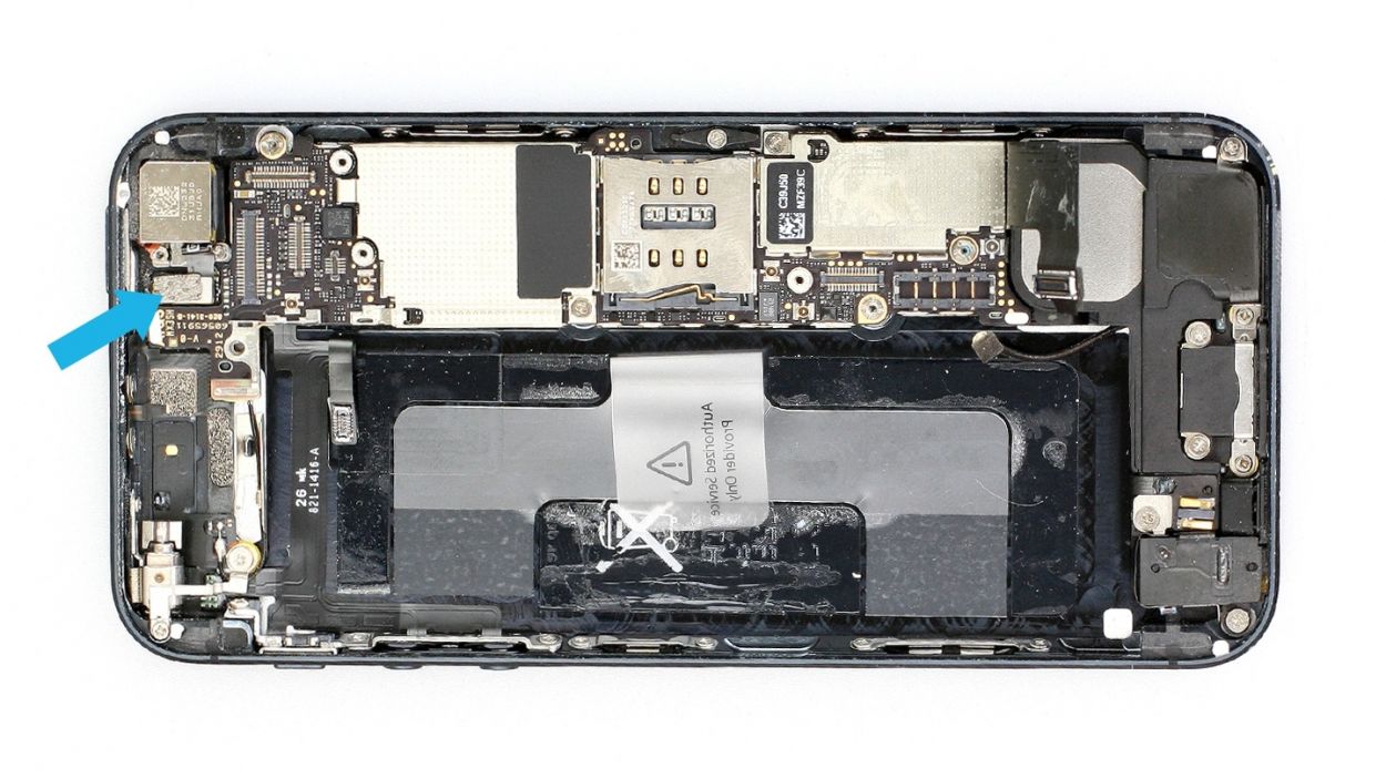
Step 12
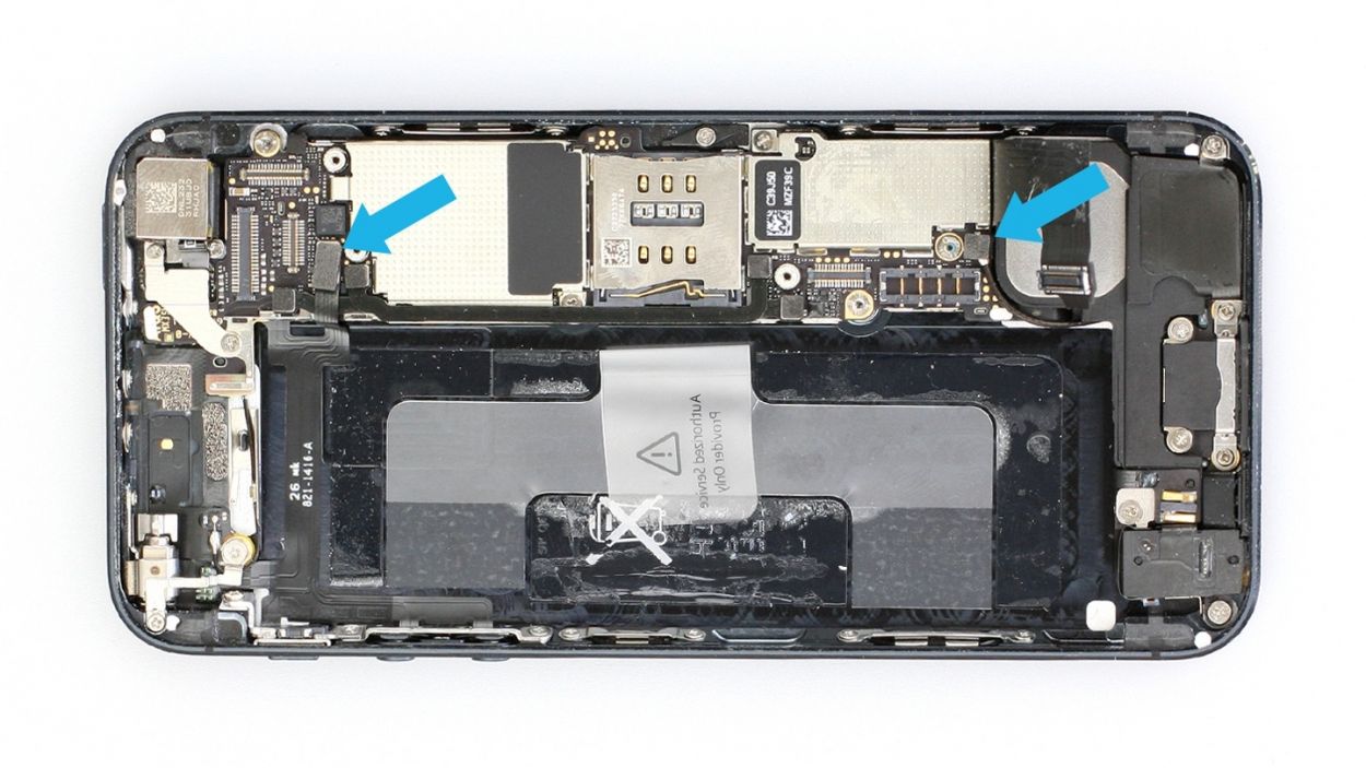
– First things first, let’s get those two connection cables out of the way (check out figures 1 and 2 for a visual!). Now, grab your spudger or spatula and gently slide the pointed tip just beneath the contact. Give it a little lift, but be super careful not to break off any of those tiny resistors that are soldered onto the logic board. You’ve got this!
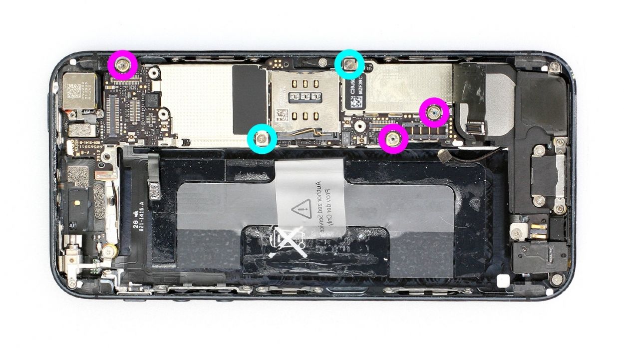
Step 13

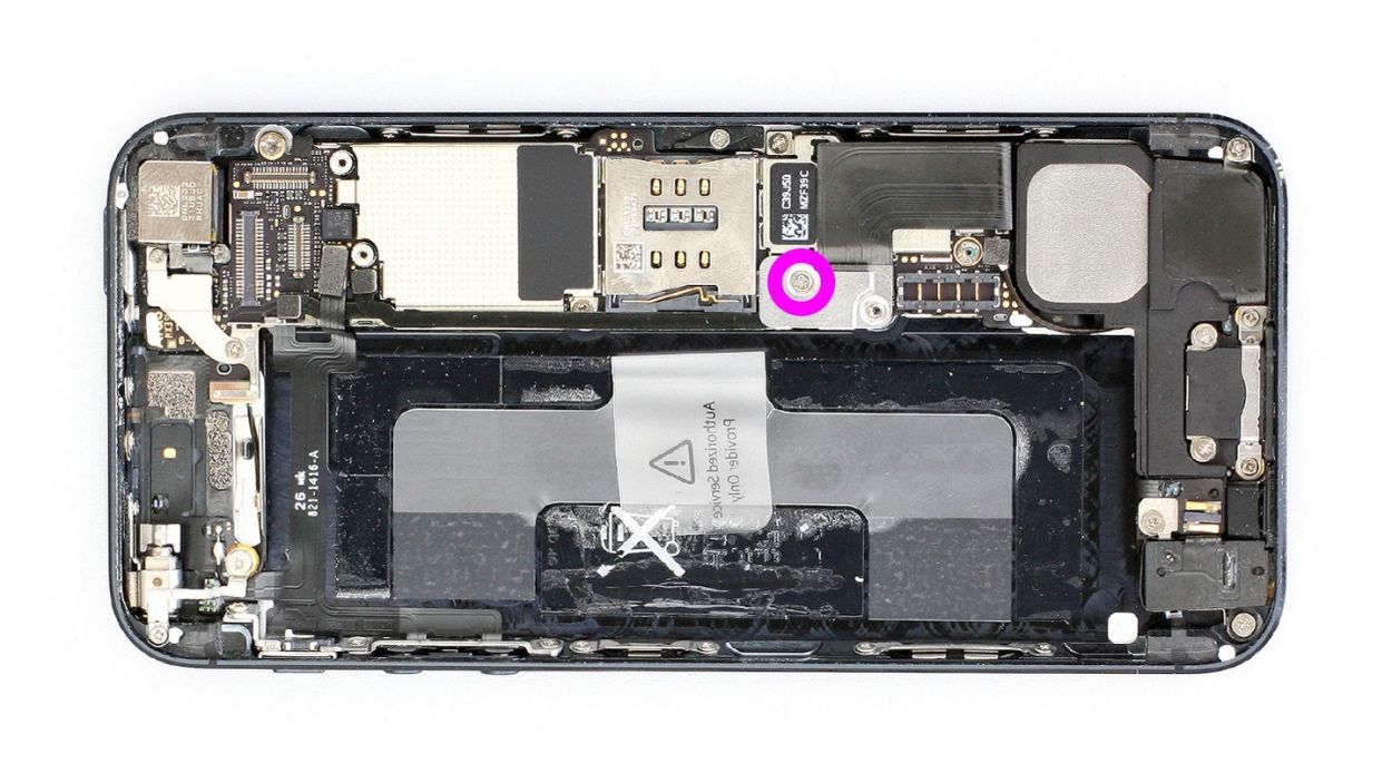
– Alright, let’s get those five screws that are keeping the logic board in check unscrewed (check out figure 1 for a visual!).
– Three of these screws are sporting an internal thread, and that sneaky one next to the rear camera? It’s not magnetic! You can easily tackle it with a flathead screwdriver or your trusty spatula. Make sure to stash all the screws in the same compartment of your organizer tray. You’ve got 3 x 2.7 mm Phillips/flathead screws and 2 x 2.3 mm Phillips screws to keep an eye on.
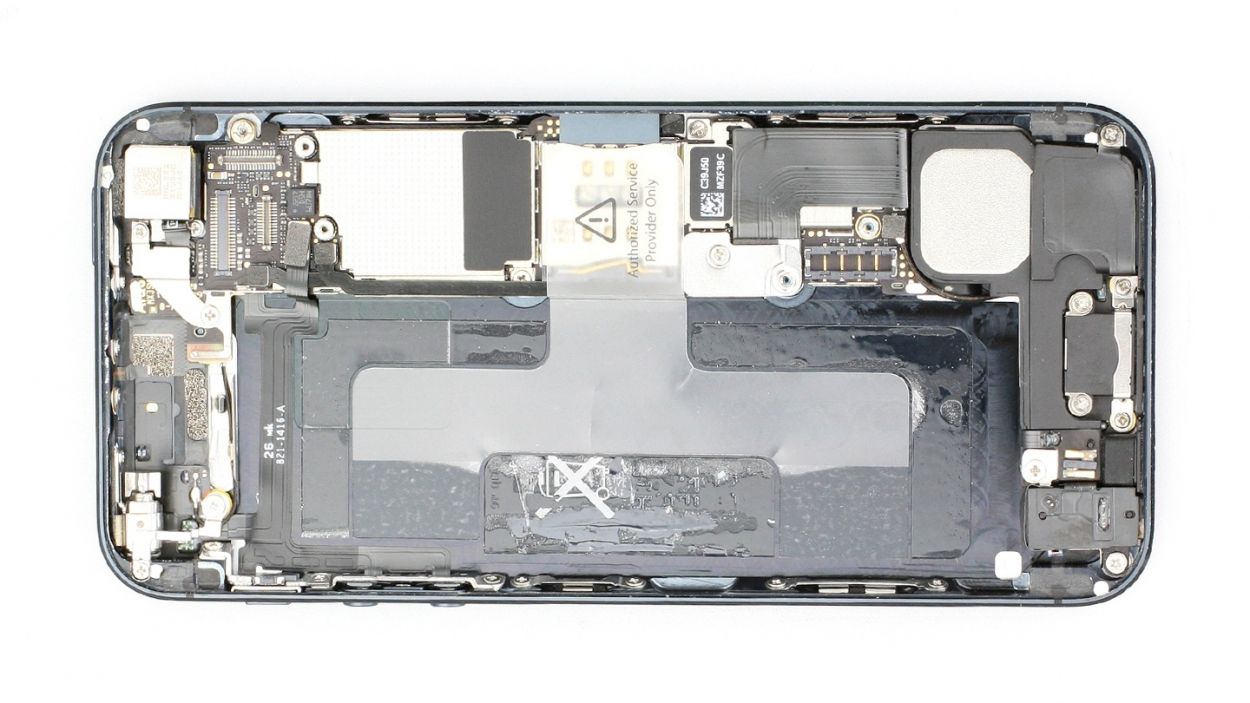
– Now, let’s give that camera flash a little lift with your laboratory spatula (see figure 2 for guidance).
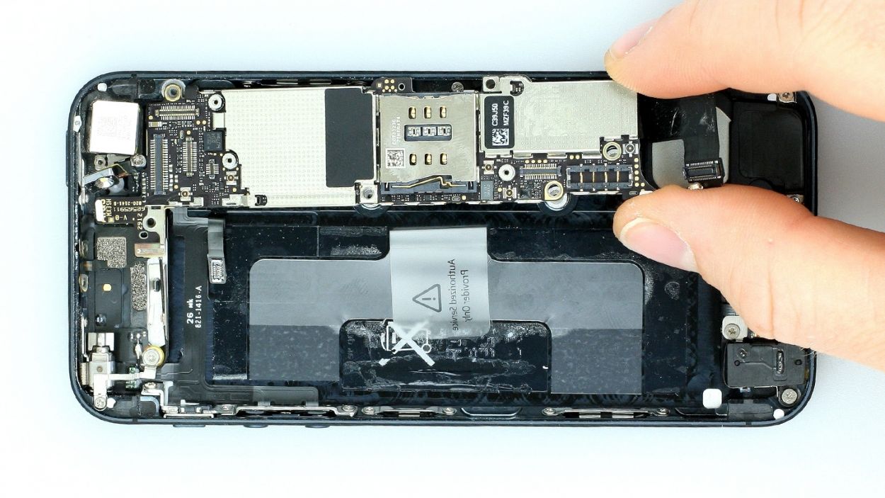
Step 14

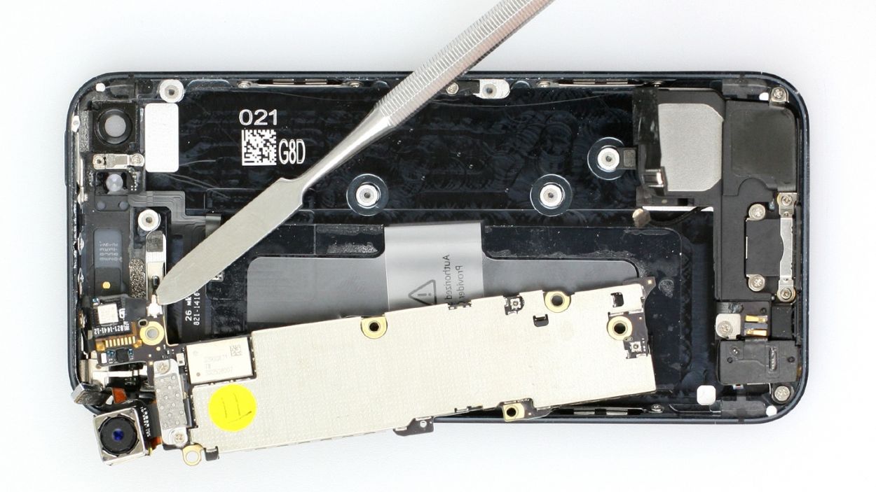
– Gently lift the logic board with your spudger (check out figure 1) and give it a little twist around the longitudinal axis using the plastic tab (see figures 2 and 3).
– Flip it over and disconnect the antenna connector by carefully pulling it off the plug head with your spudger (see figure 3).
– Now, with a steady hand, remove the logic board.
Step 15

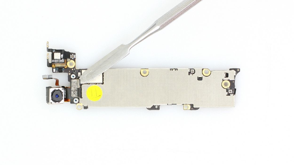
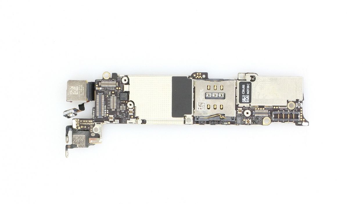
– The camera connection is located on the back of the logic board. No need to panic!
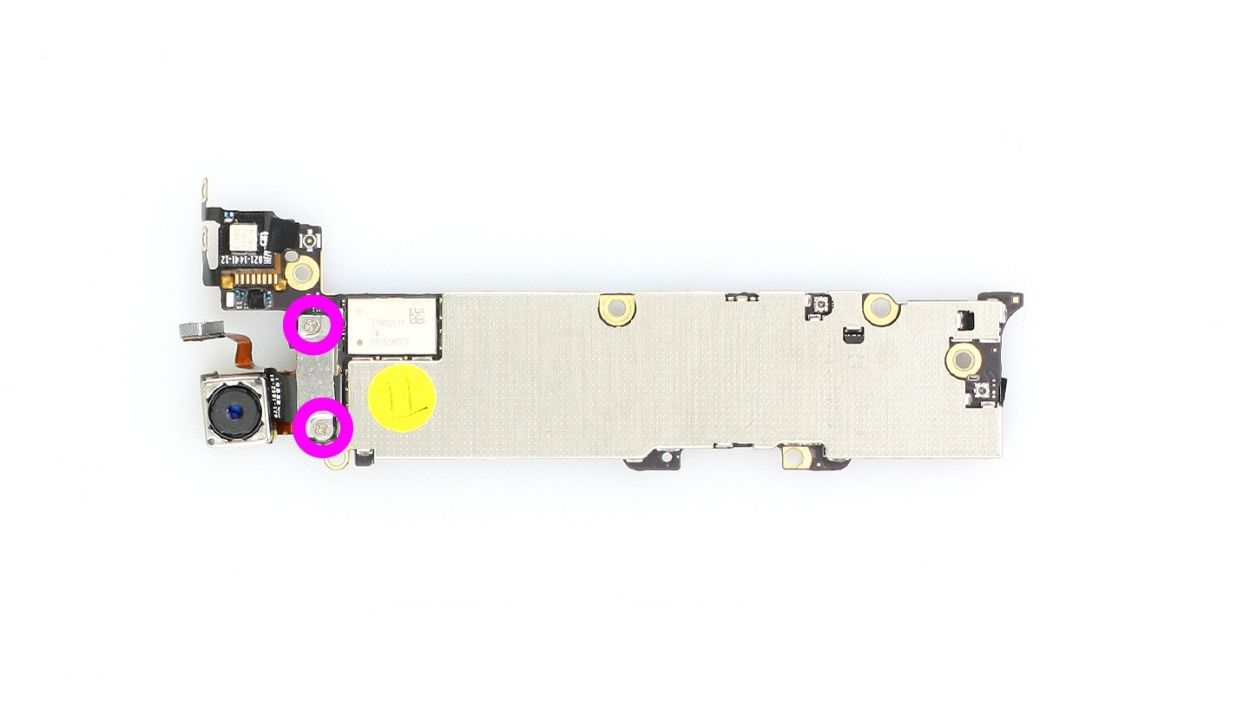
– Unscrew those two Phillips screws and remove the cover (check out figure 1 for a visual). You’ve got 2 x 1.2 mm Phillips screws to keep track of!
– Now, let’s disconnect the connector. Gently slide the pointed tip of your spudger just below the contact and give it a little lift (see figure 2). You’re doing great!
Step 16
– Connect the camera, place the shiny silver cover back on, and secure it with those two 1.2 mm Phillips screws. You’re almost there!
Step 17
– Reconnect the WLAN antenna connector to the logic board (check out figure 1) and gently place the logic board back in its original spot (see figure 2). Use figure 4 to ensure your logic board is sitting just right.
– Time to pop in that camera flash (see figure 3).
– Now, let’s secure everything by screwing in all five screws that hold the logic board in place (see figure 4). You’ve got 3 x 2.7 mm Phillips/flathead screws and 2 x 2.3 mm Phillips screws to keep track of!
Step 18
– Reconnect those two connection cables like a pro! Just make sure those connectors are snug as a bug in a rug.
Step 19

– Tighten up those two Phillips screws that are keeping the antenna cozy with the frame. You’ve got 2 x 1.3 mm Phillips screws to keep an eye on!
Step 20

– Time to get that bracket in place! Secure it with the two Phillips screws and you’re all set. You’ve got 1 x 2.3 mm Phillips screw and 1 x 1.5 mm Phillips screw to keep an eye on!
Step 21
– Reconnect the antenna connector and the standby/volume cable set connector (check out figure 1 for a visual!).
– Next, plug in the ribbon cable, cover it up, and secure it with a screw (see figure 2). You’ve got a 1 x 1.2 mm Phillips screw to keep an eye on!
Step 22
– If you pulled out that plastic tab with the warning, give it a little love and pop it back in. If it’s still in there, just give it a gentle nudge to make sure it’s snug. We want everything to stay in place while you work your magic!
Step 23

– Alright, time to slide that battery back into your iPhone! Make sure it’s cozy and snug against the logic board.
– Give that battery connector a little click to lock it back in place.
– Now, let’s wrap it all up! Pop the cover back on and secure it with those screws: 1 x 1.8 mm Phillips screw (funnel head) and 1 x 1.7 mm Phillips screw. You’re doing great!
Step 24

– Alright, let’s get those connectors reconnected (check out figure 1 for a visual!). Just a heads-up, the LCD connector can sometimes play hide and seek when you plug in the touchscreen connector. We’re talking about the LCD, touchscreen, front camera/sensor, and earpiece here!
– Next, reattach that battery connector and give the cover plate a little love by securing it back in place.
– Once everything is snug, power up your iPhone and give it a whirl! Make sure the LCD, touchscreen, proximity sensor, front camera, and earpiece are all functioning as they should.
– Now, let’s put the cover back on and screw it in tight (see figure 2). You’ll need 2 x 1.2 mm Phillips screws and 1 x 1.7 mm Phillips screw (just a little reminder, that last one isn’t magnetic!).
– Finally, gently fold down the screen. Ensure that the edge of the screen where the cables are clicks into place just right. Carefully press the screen towards the Home button until it’s snugly installed in the frame. (Take a peek at figure 3 for guidance!)
Step 25
– Now screw in the two pentalobe screws at the bottom of the enclosure.2 x 3.6 mm pentalobe screws
Step 26

Removing the battery can make your iPhone a bit forgetful, resetting the time to 1:00 a.m. on 1/1/1970. So, if you want to avoid any hiccups with your cellular connection, be sure to set the time right after!
– Sync up your iPhone with iTunes or hop onto a WLAN network and hang tight until the time is all set!
– Pop out that SIM tray with the SIM card and give it another go by reinserting it.
– Turn on airplane mode for a moment and then switch it off again.