Asus ZenBook Flip UX360C Motherboard Replacement
Duration: 45 minutes
Steps: 7 Steps
This step-by-step guide walks you through swapping out the motherboard in the Asus ZenBook Flip UX360C. Heads up: we’re using a metal spudger here to pry and poke inside the device. However, metal tools can be a bit too eager and may damage internal components or cause harm—especially around the battery. For safety and peace of mind, opt for an ESD-safe tool instead. If you need a hand or want to make sure everything’s done right, you can always schedule a repair.
Step 1

– Take out all ten T5 screws hanging out near the edges of the back cover—don’t let any escape!
– Next up, pop out the two Phillips #1 screws hiding under the rubber feet by the screen. Sneaky, but not sneaky enough.
Step 2


Heads up! Don’t yank the keyboard off just yet—there are two ribbon cables still connecting it to the motherboard.
– Grab a metal spudger and carefully pop the keyboard away from the case—easy does it, no wild moves needed.
– Gently lift the keyboard out and set it aside like the VIP it is.
– Tilt the keyboard up just a bit and use a plastic spudger to unclip both ribbon cables from their ZIF connectors—take your time, no rush!
Tools Used


Step 3

– Grab your trusty Phillips #1 screwdriver and unscrew all those 5 mm screws like a pro!
Tools Used

Step 4

– Gently pop those monitor connectors off the main board using a plastic opening tool or a nylon spudger. Nice and easy—no need to rush this part!
Tools Used
Step 5

Metal spudgers are cool, but they can be a little too edgy for your device—especially near the battery! Play it safe with an ESD-safe tool instead. Your phone will thank you!
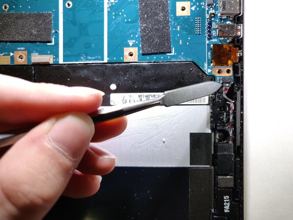
– Gently detach the battery from the main board, taking care not to rush. A little patience here goes a long way.
Tools Used
Step 6

Be careful with that metal spudger! It can be a bit of a troublemaker and might cause some damage to your device or even hurt you, especially around the battery area! Instead, grab an ESD safe tool to keep things safe and sound.
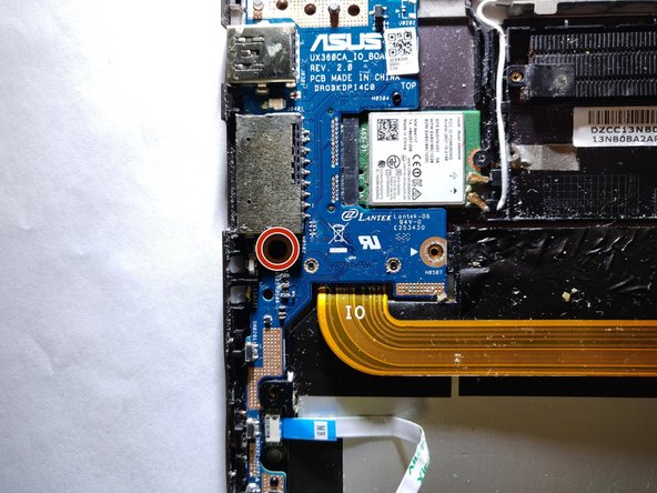
– Peel off that black foam sitting above the screw on the I/O board.
– Take out the 5 mm Phillips #1 screw.
Tools Used
Step 7


– Gently wiggle the I/O board away from the chip to let it go free.
– Carefully lift out both the I/O board and the main board.
Success!