DIY Guide to Replace Galaxy S9 USB-C Port
Duration: 60 min.
Steps: 24 Steps
If your Galaxy S9 is giving you the silent treatment when it comes to charging, it might be time to check that USB-C port. A quick swap could bring back the magic of fast charging and smooth file transfers. And remember, if you need help, you can always schedule a repair!
Step 1

Tap the tiny Play button in the upper right corner of an image to watch a video for each step. It’s a great way to see the action in motion!
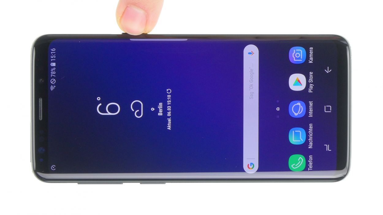
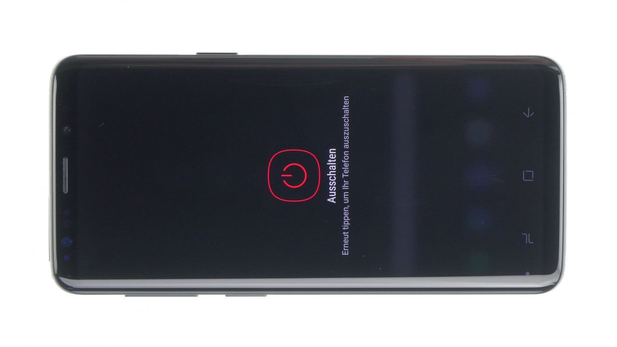
– First things first: Hit that power button and hold it down until you see the ‘Power off’ option. It’s time for a little device downtime!
– Tap to confirm and say ‘see ya later’ to your screen. Once it’s nice and blank, we’re ready to roll!
Step 2

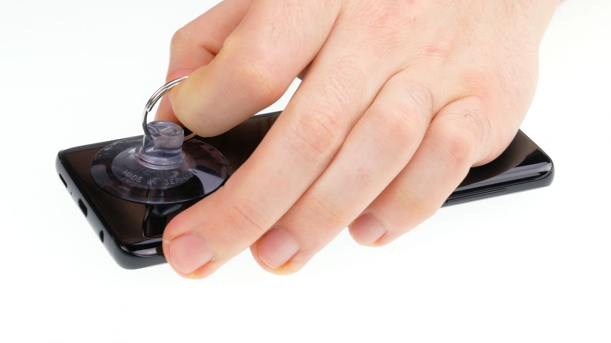

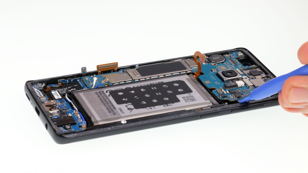
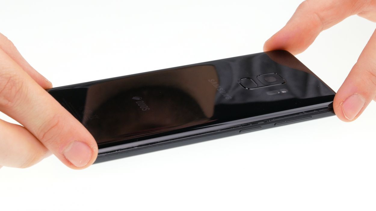
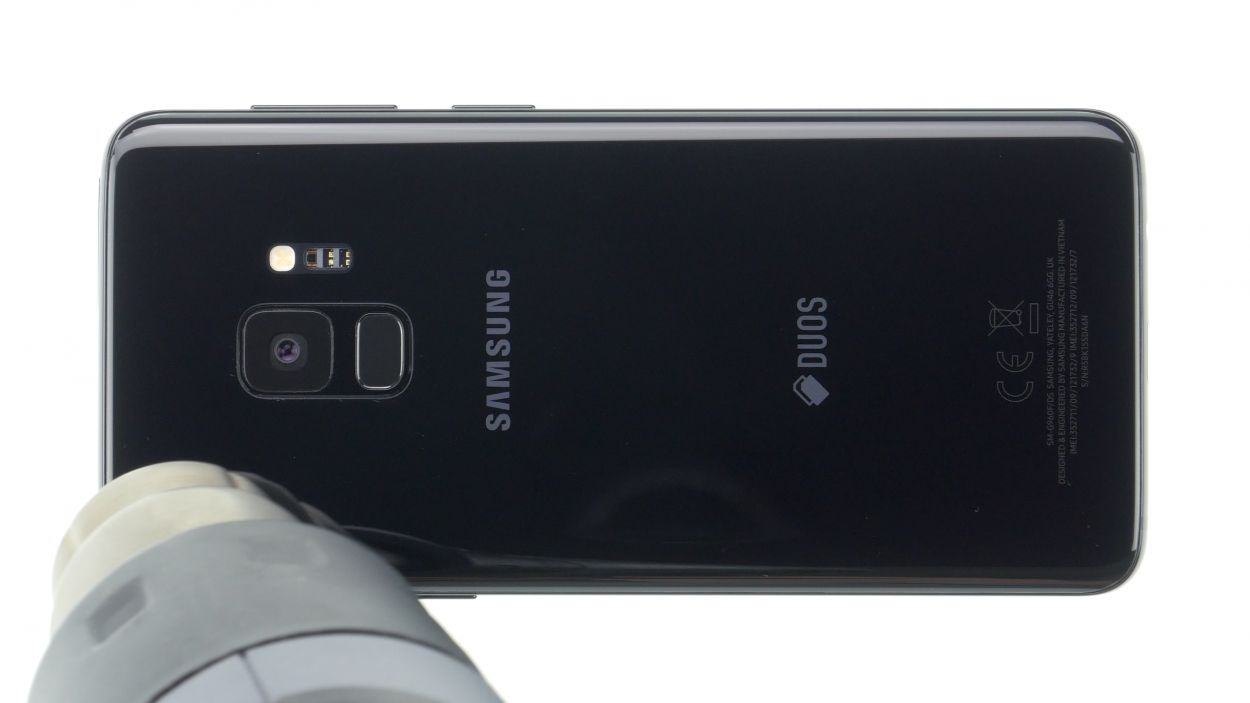
– Warm up the area where you’ll begin and stick a suction cup on the bottom of the back cover. It’s like giving your device a cozy hug!
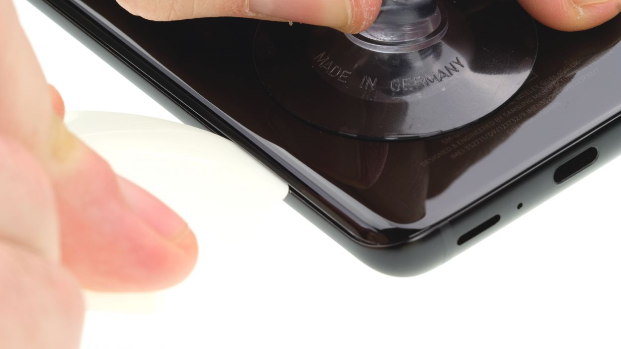
– Slide a flat tool gently between the back cover and the frame while pulling on the suction cup. Think of it as a little tug-of-war, but with your device’s back cover!
Hey there! Just a friendly reminder to handle that back cover with care—it’s a bit fragile! If it’s giving you a hard time, feel free to warm it up a few times and give it another go. Remember, taking your time is key; it might take around half an hour, but being patient will help you avoid any mishaps. You’ve got this!
The iPlastix is crafted from plastic, ensuring it won’t leave any scratches on your device. However, it’s a bit on the softer side, which can make inserting it a little tricky. Just take your time and you’ll get the hang of it!
Tools Used
- Heat gun
- screen and the frame. The practical iFlex is made of stainless steel and sits comfortably in the hand. This makes it the perfect assistant for every smartphone repair.” rel=”noopener”>iFlex Opening Tool
- VAKUPLASTIC Suction Cup
Step 3

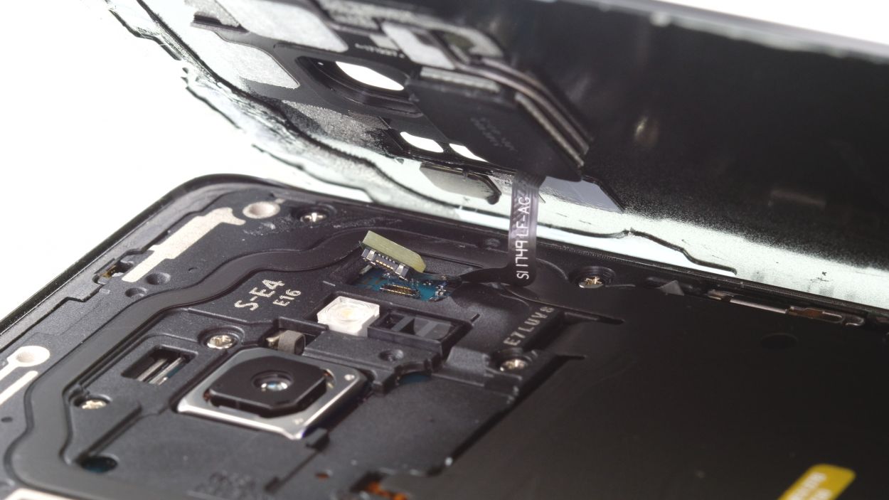
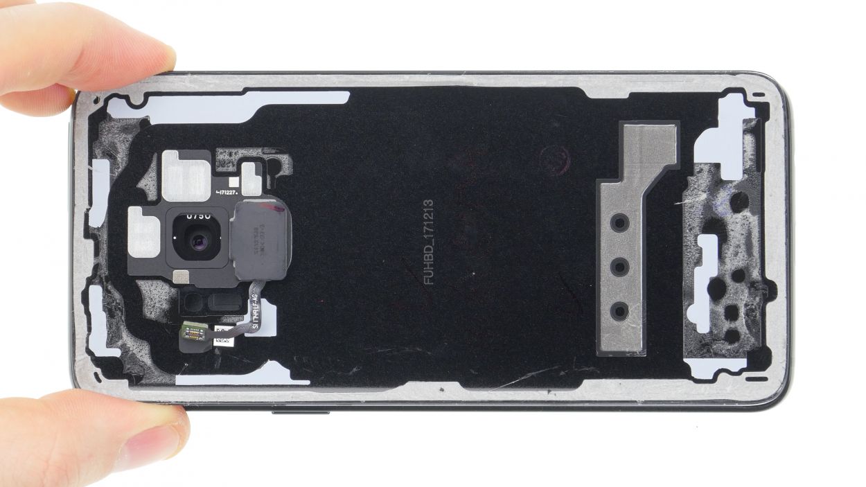
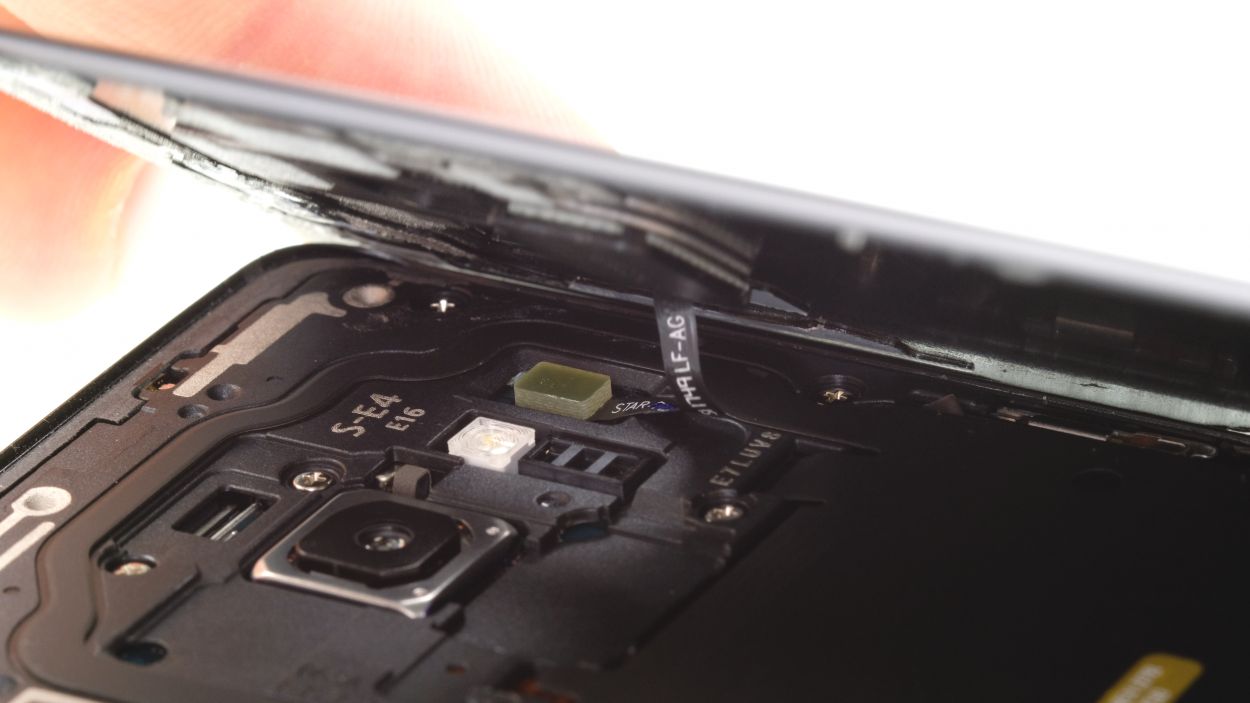
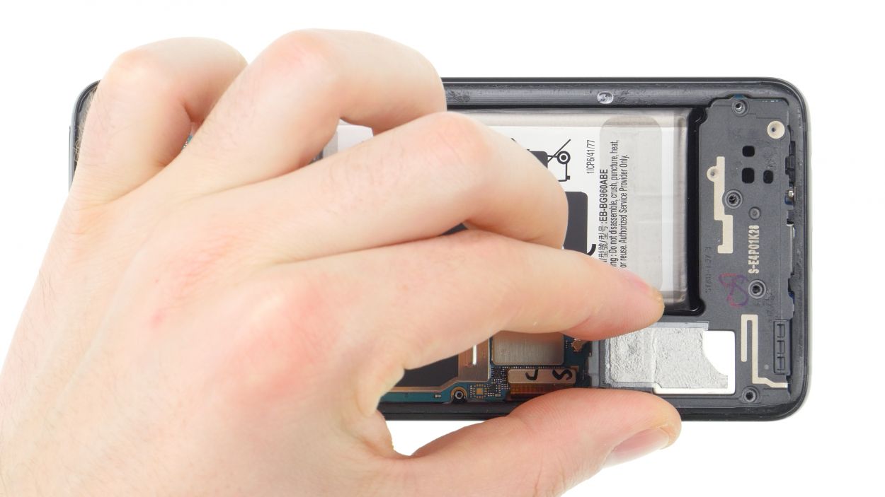
– Once you’ve popped off the back cover, gently lift it up, and use the spudger to disconnect the fingerprint sensor with a little finesse.
– Now, go ahead and fully remove the back cover, and feel free to set it aside for the time being.
Tools Used
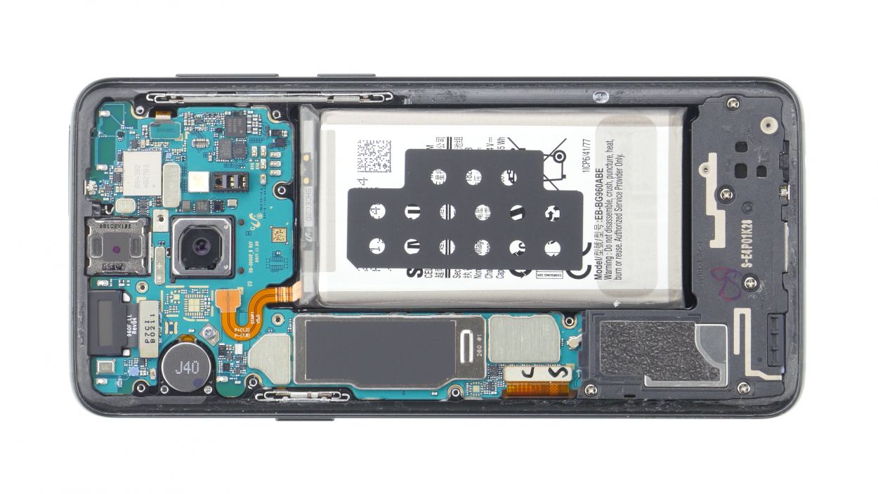
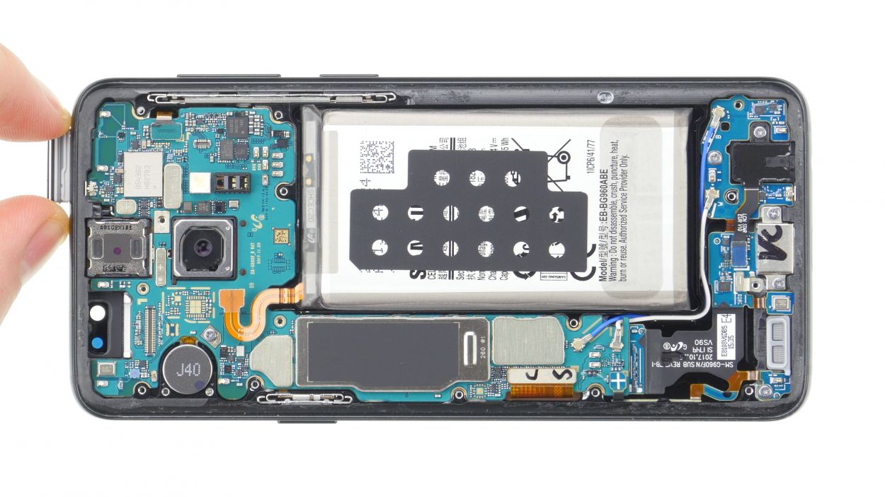
Step 4
10 × 4.0 mm Phillips
This phone only has two types of screws, so it’s pretty straightforward! If you find any screws that are being a bit stubborn, grab a pair of tweezers to help you out. Remember, if you need assistance, you can always schedule a repair!
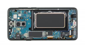
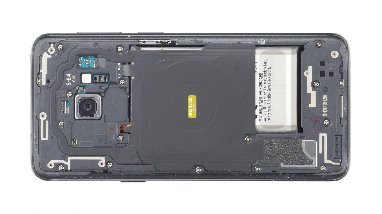
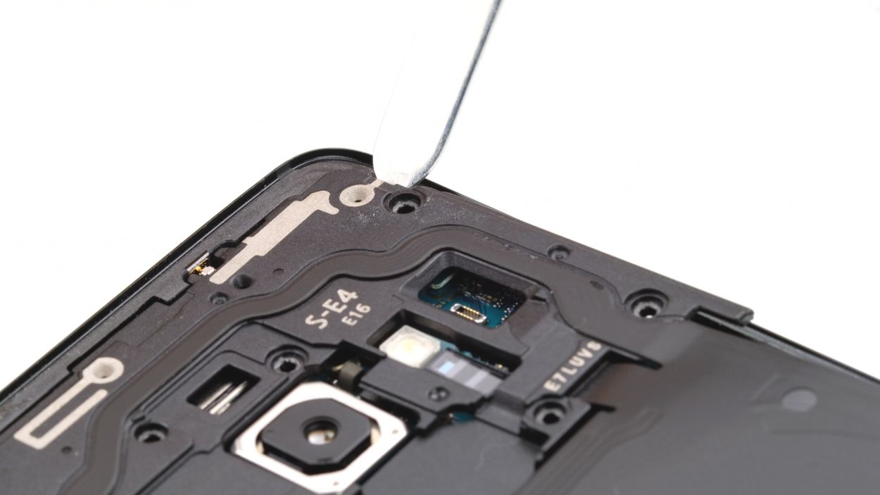
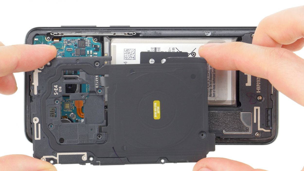
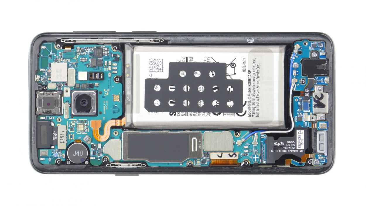
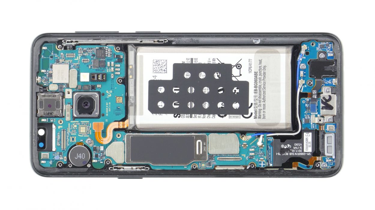
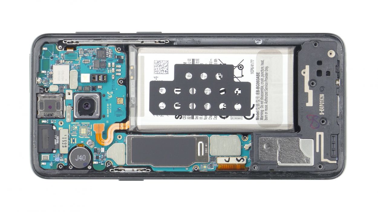
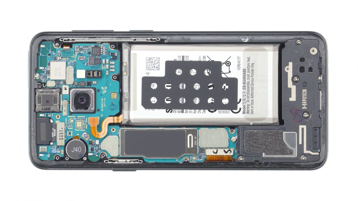
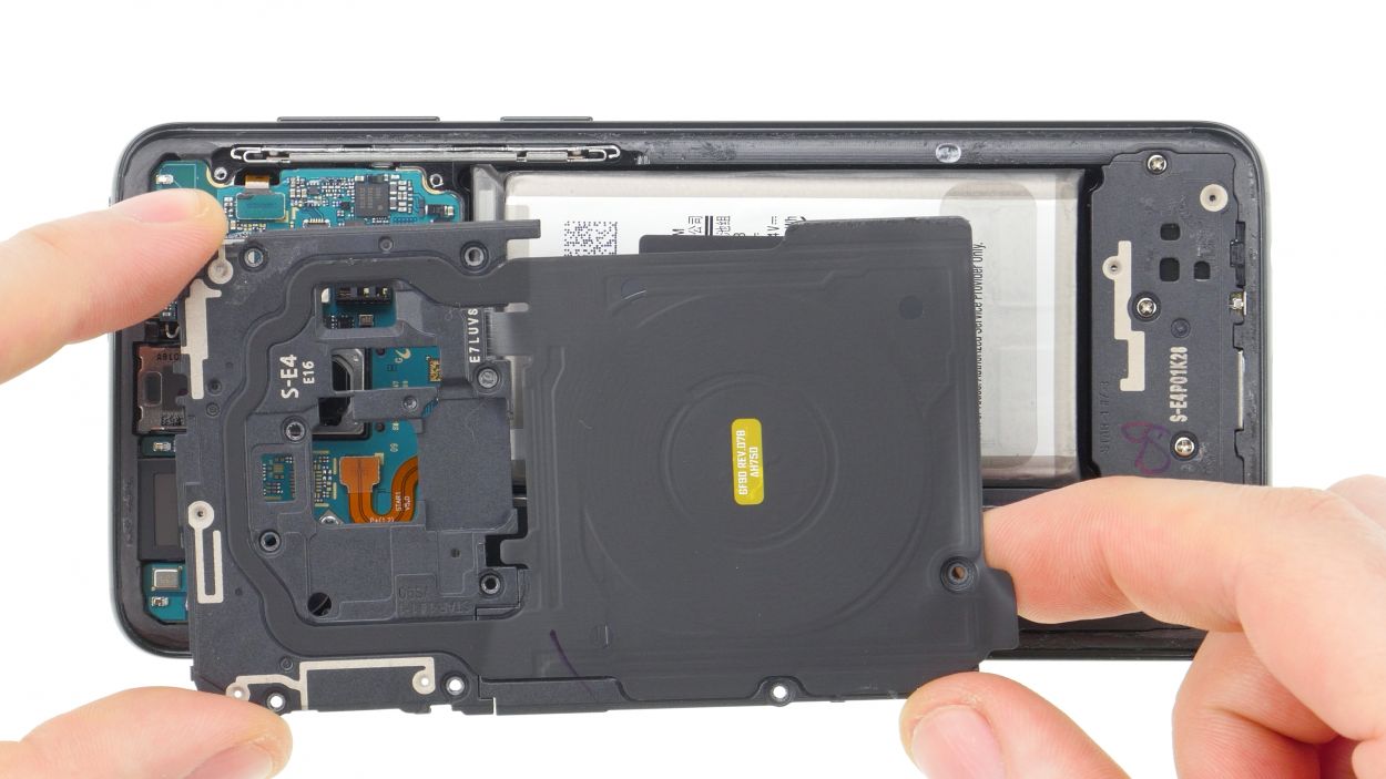
– The top of the logic board cover, which has the NFC tag, is securely latched in place.
– Gently pry it up just a bit and then lift it out with care.
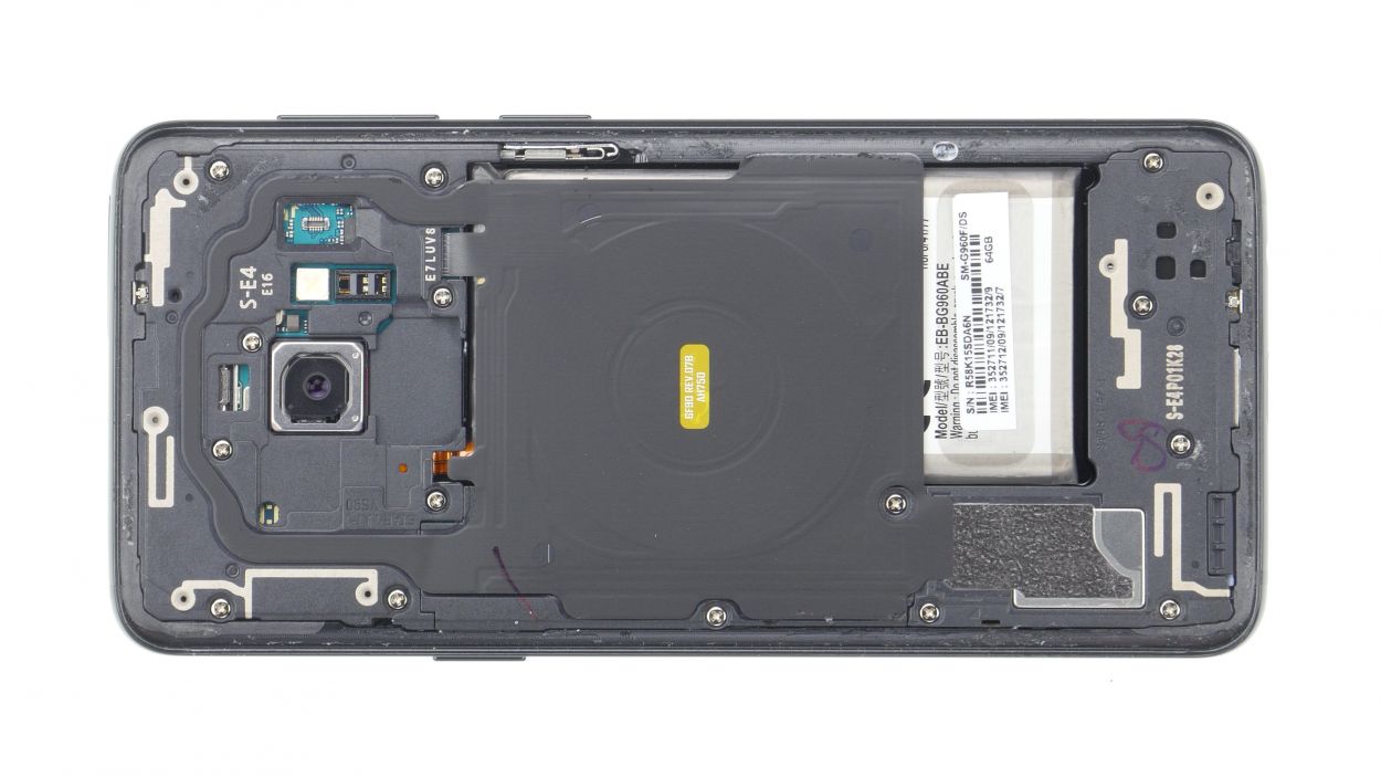
Step 6

5 × 4.0 mm Phillips
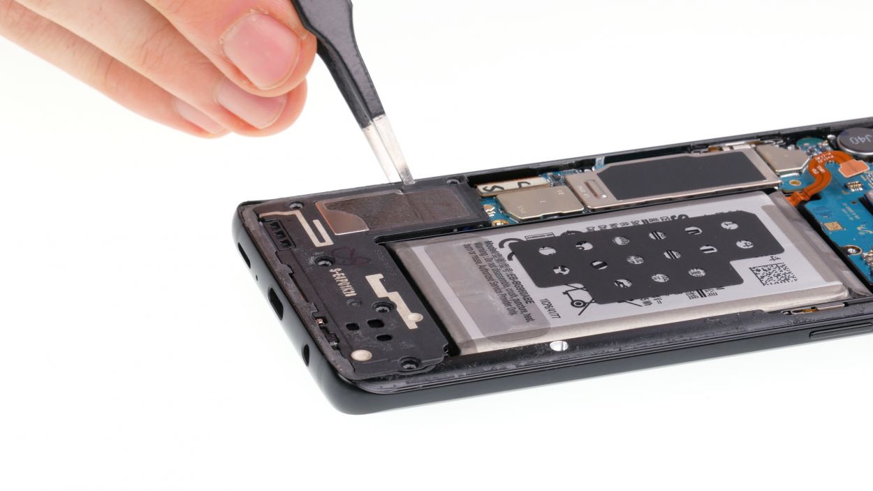
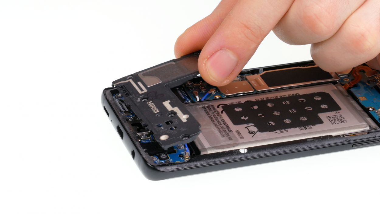
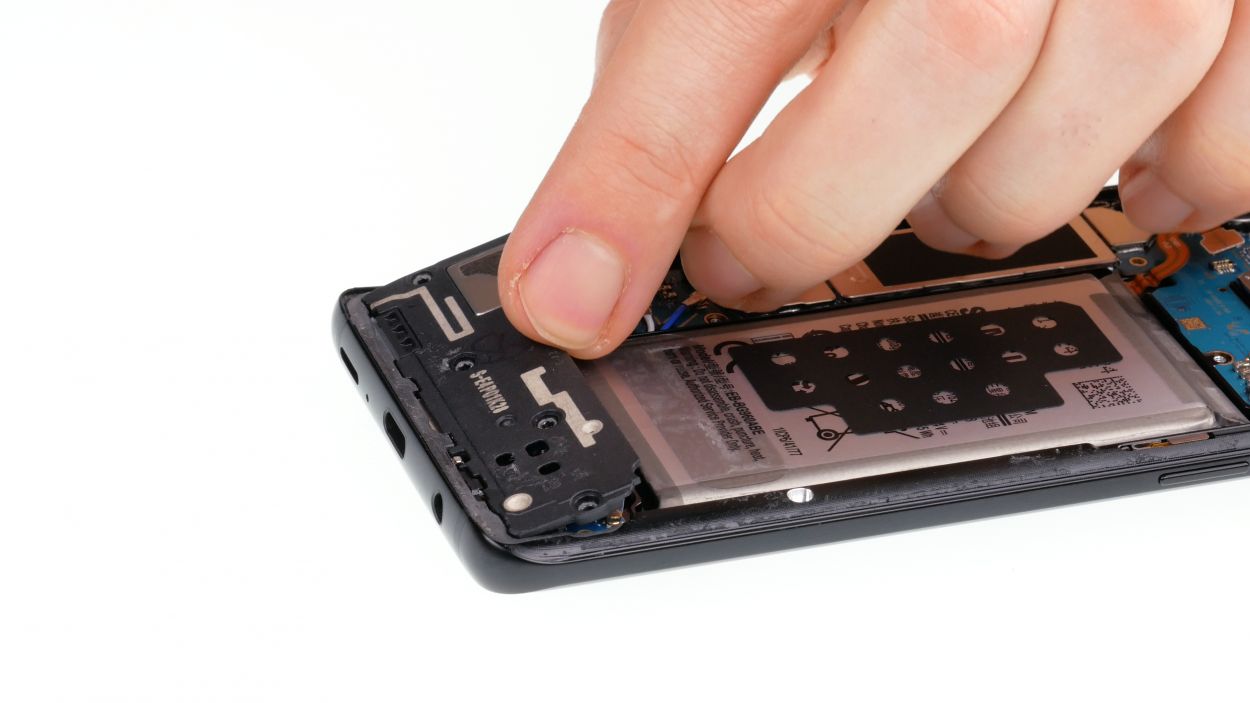
– Gently lift the speaker with your trusty tweezers, and then go ahead and take it out!
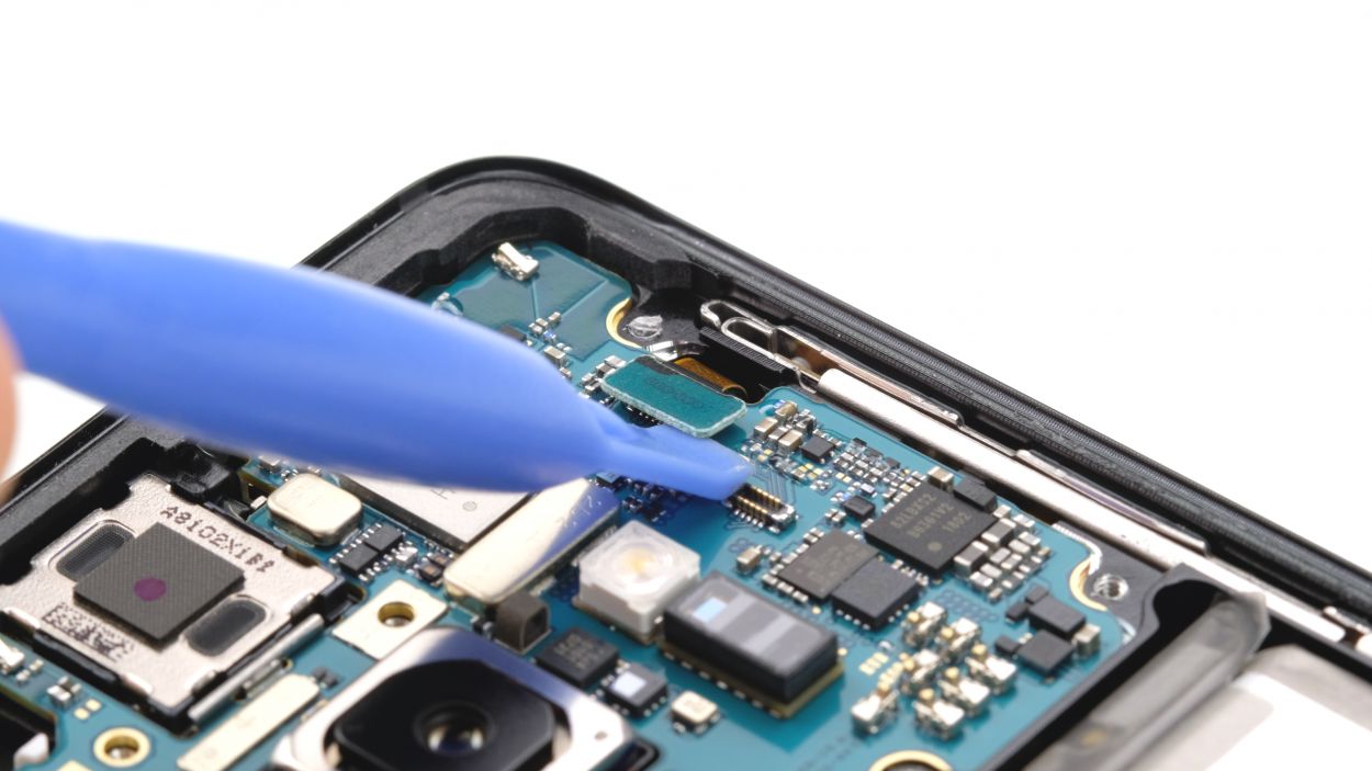
Step 7
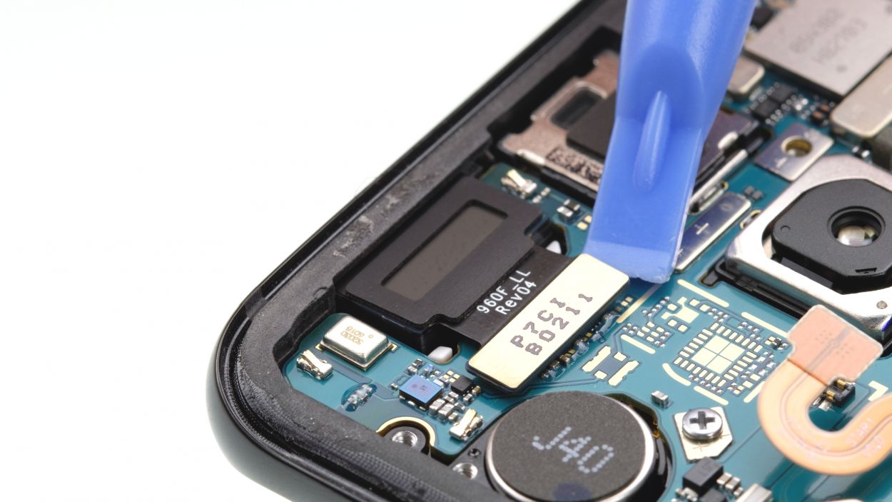

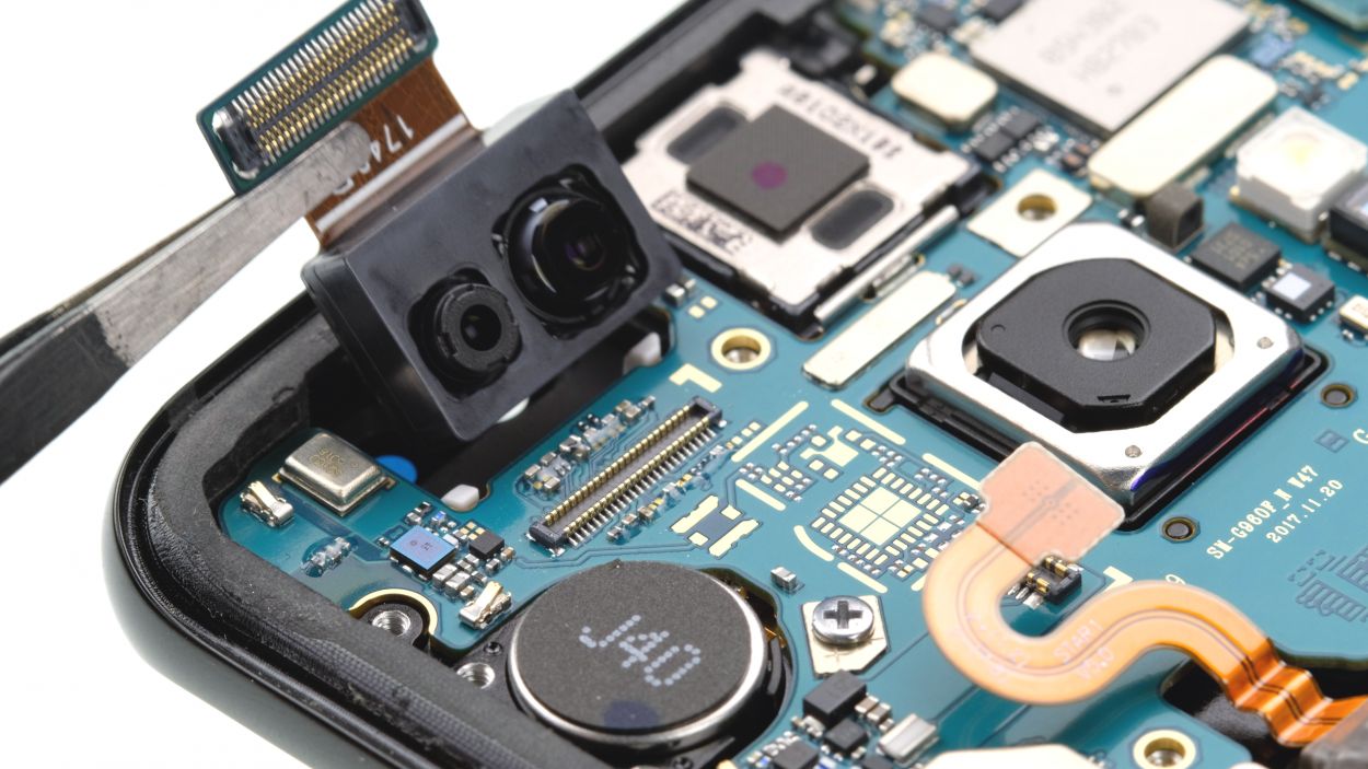
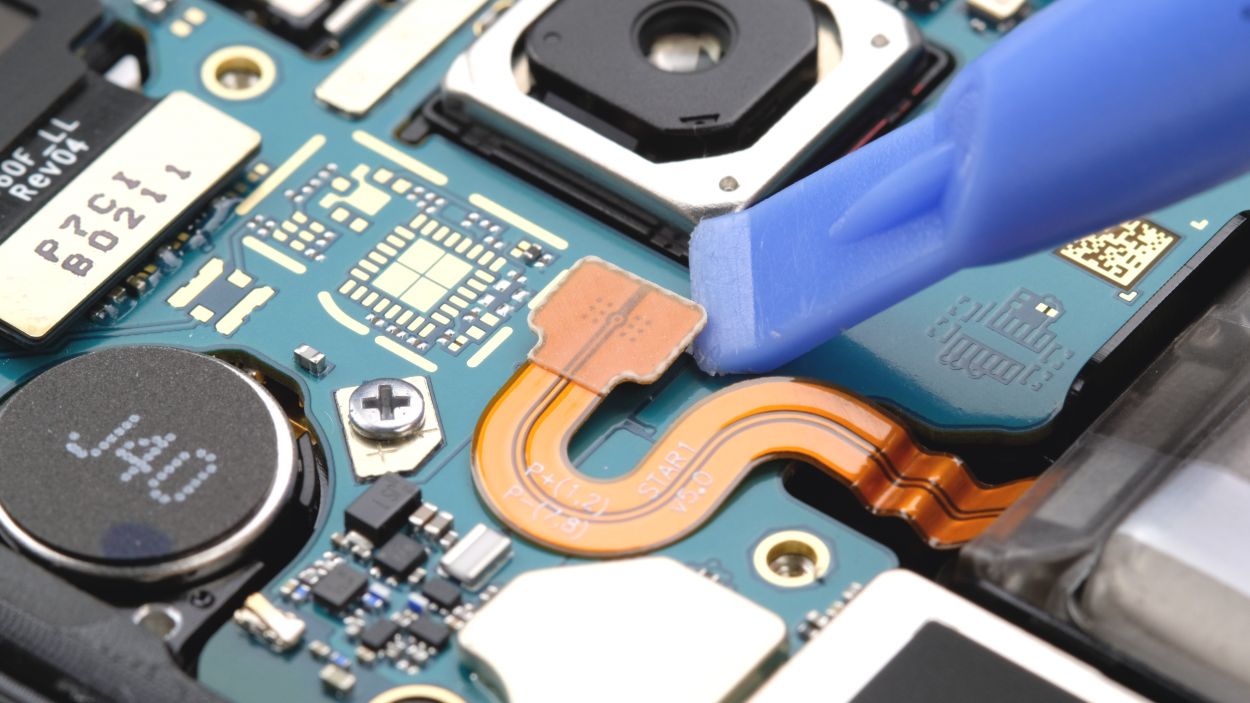
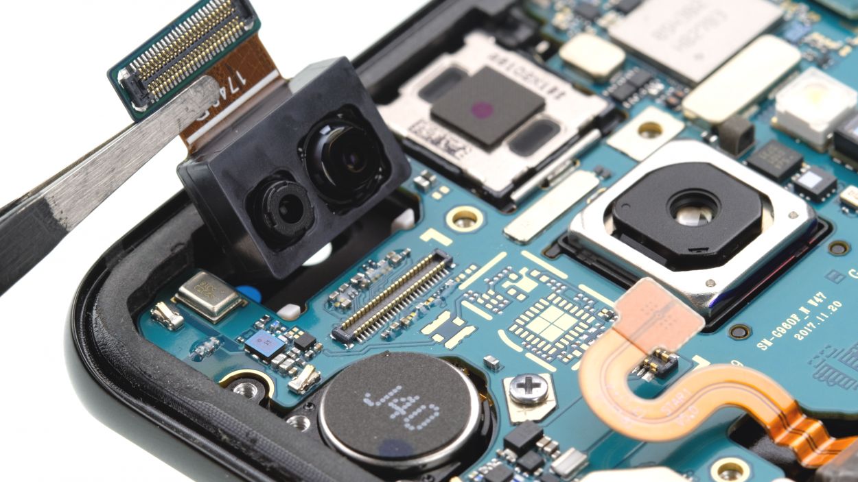
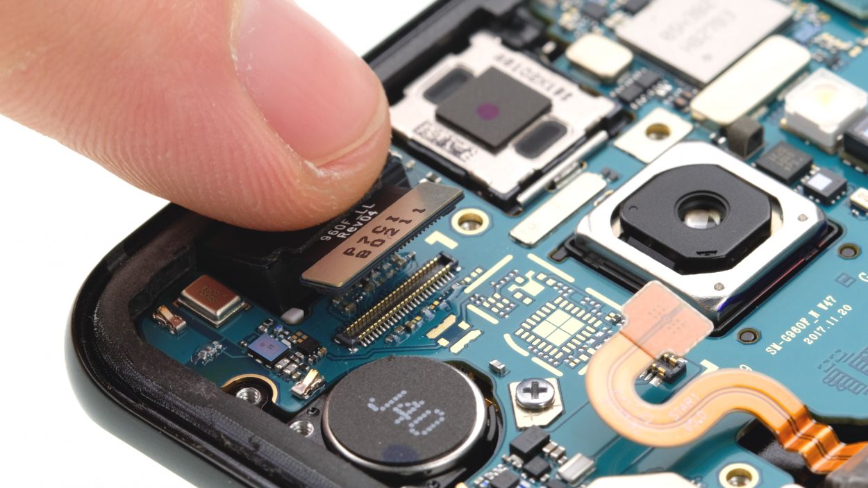
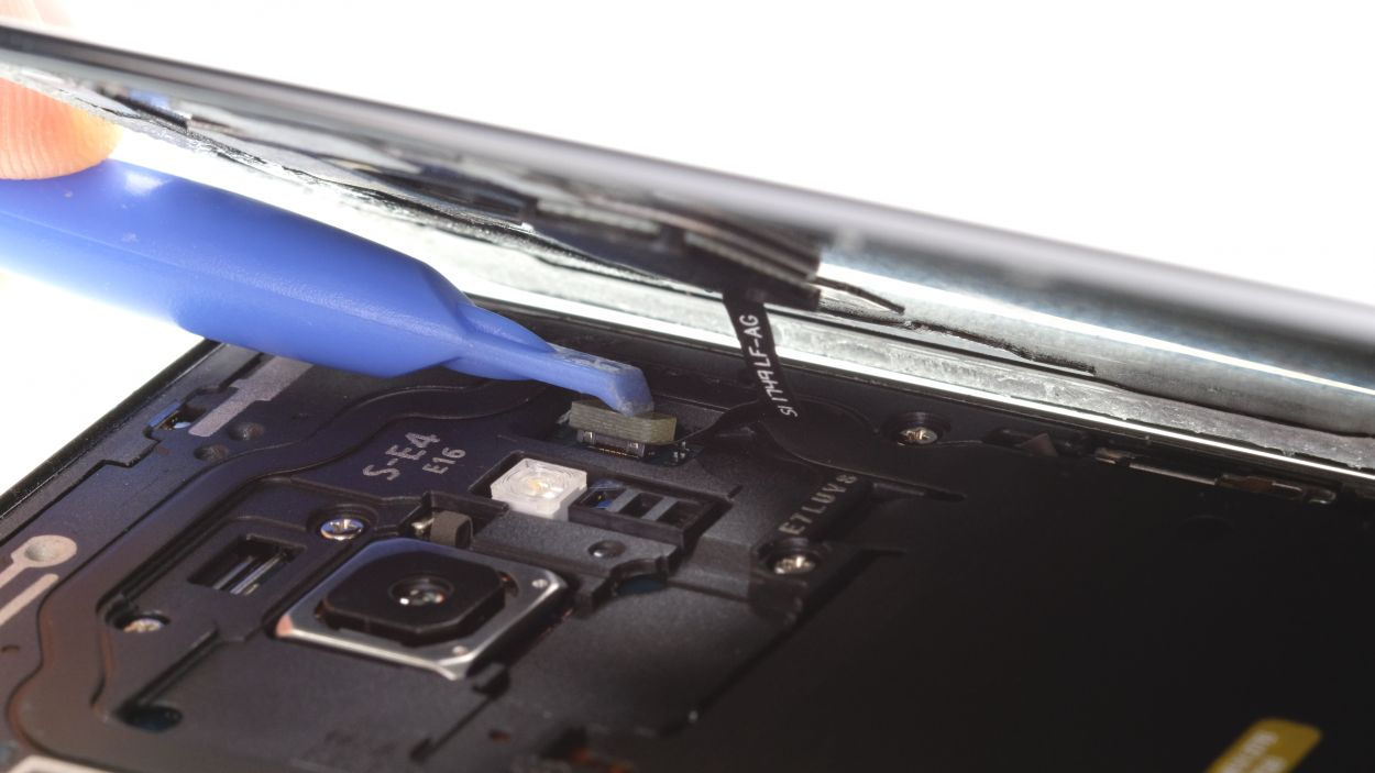
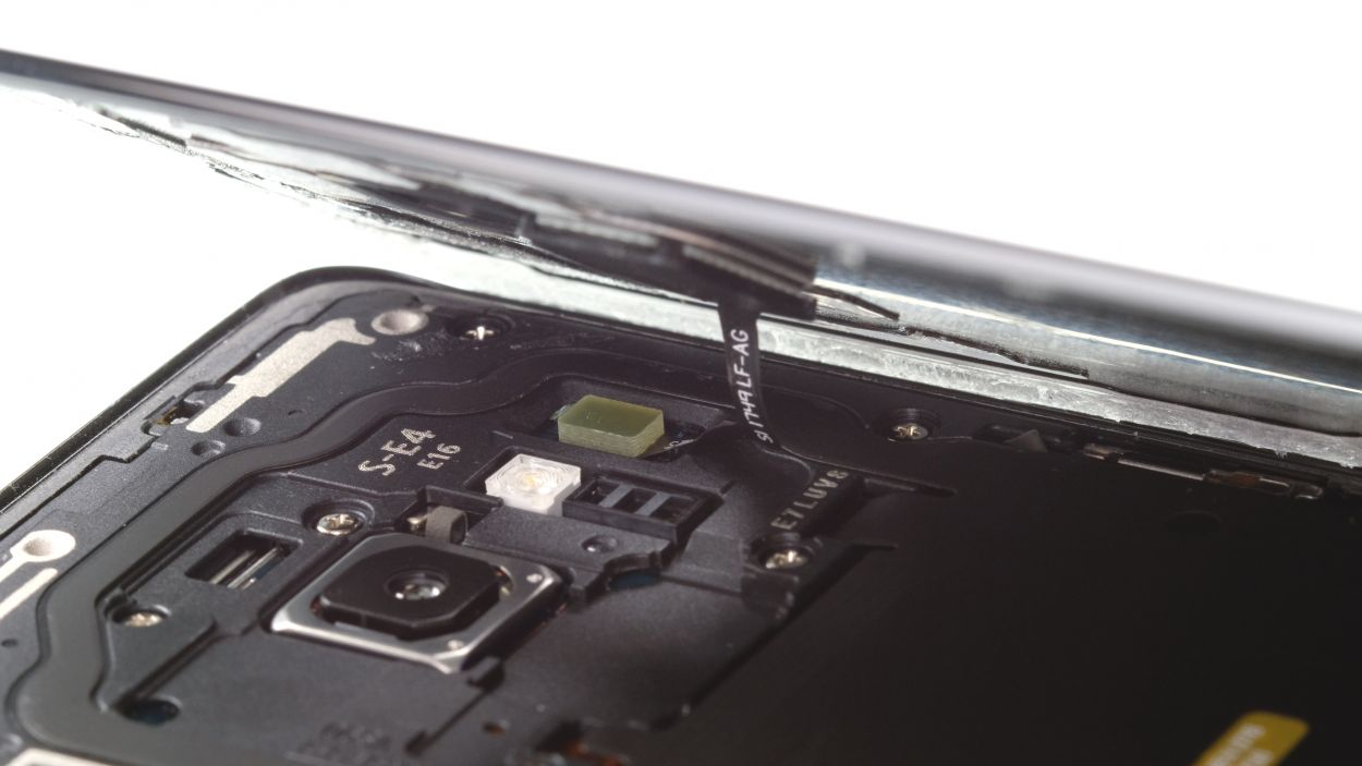
– First up, gently disconnect the front camera connector with your trusty spudger.
– Carefully pry it up from the side that’s free of any PCB components.
– Now, with a little finesse, lift the camera out of its snug holder.

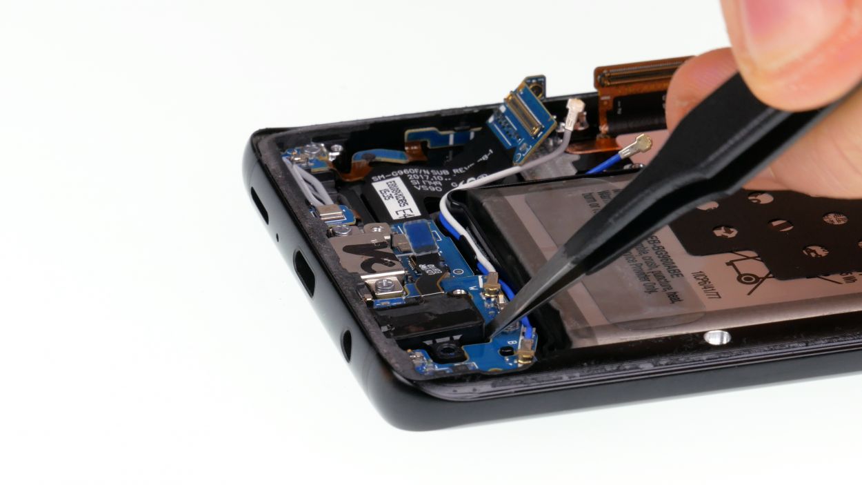
Step 9

Antenna Plug
– First things first, let’s unplug those connectors from the logic board. You’ve got this!
– Gently twist the spudger – it’s not a crowbar, so treat it with care to keep the logic board safe.
– Watch out for those tiny parts near the connectors; they can be a bit delicate.
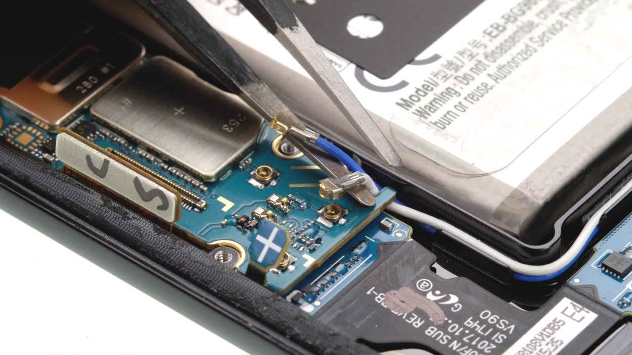
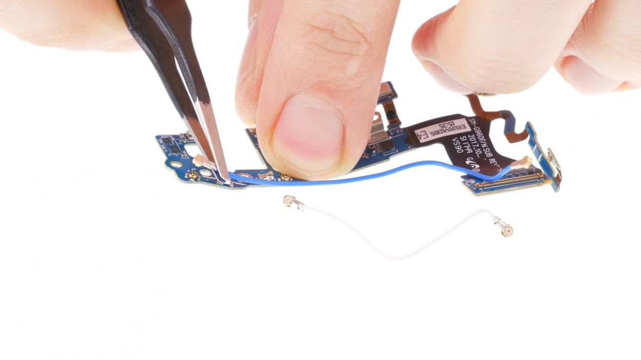
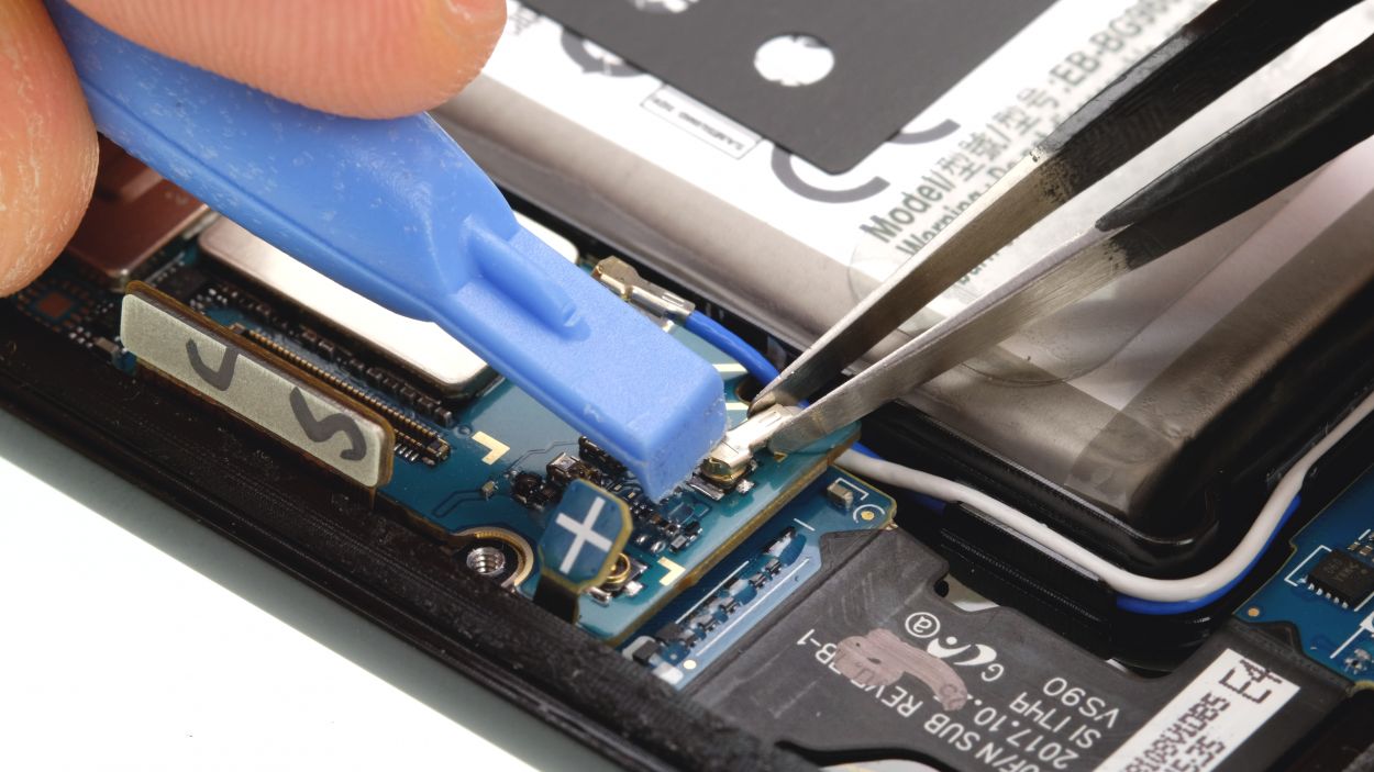
– Next up, it’s time to disconnect the button plugs of the antenna cables. Easy peasy!
– When grabbing the cable, use tweezers and avoid the plug itself. You’re doing great!
– To disconnect the plug, just give it a little twist with the tweezers. Smooth moves!
Step 10
1 × 3.4 mm Phillips
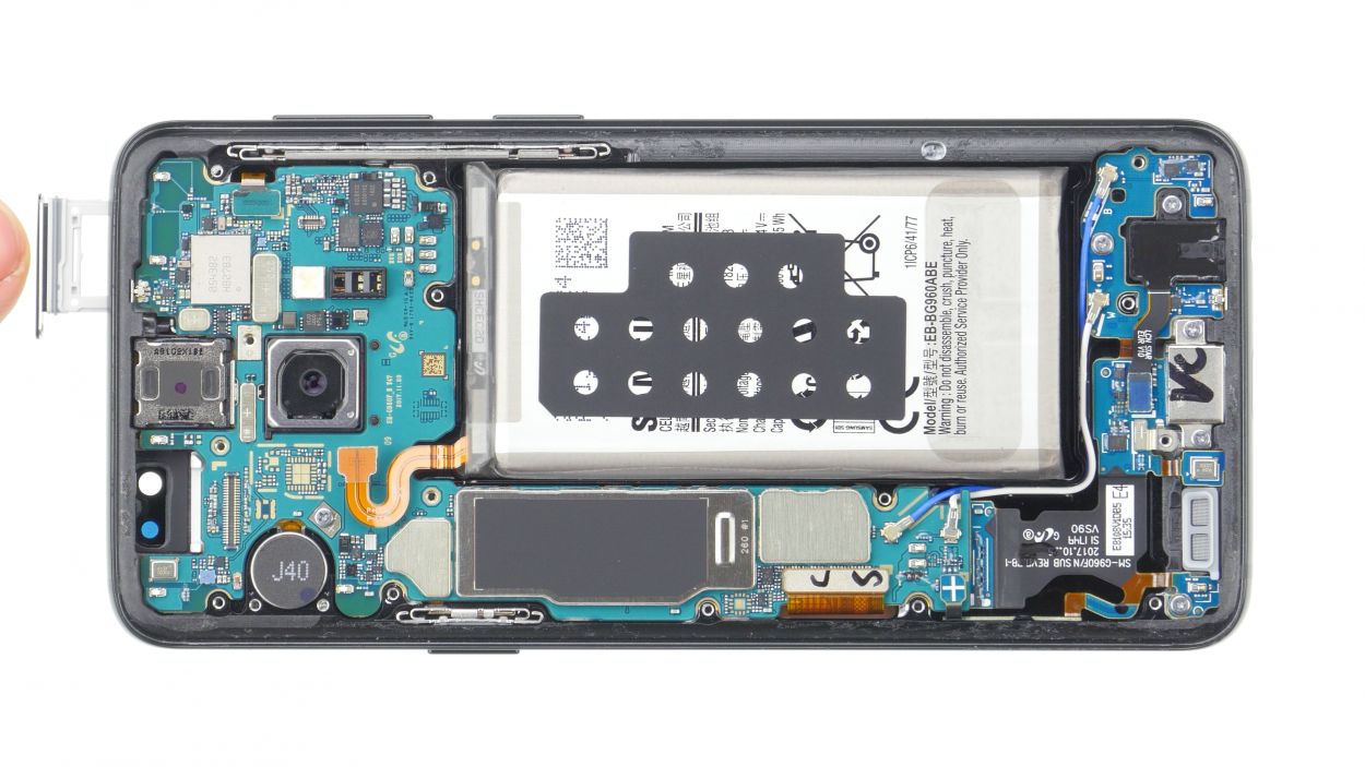
Hey there! Just a heads up, there’s a tiny plastic pin hanging out in the SIM tray opening. Keep an eye on it so it doesn’t decide to take a little tumble!
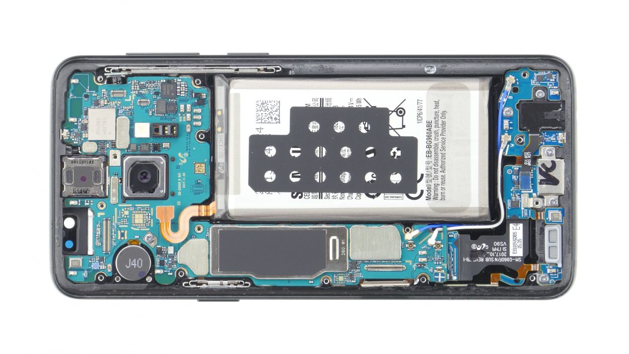
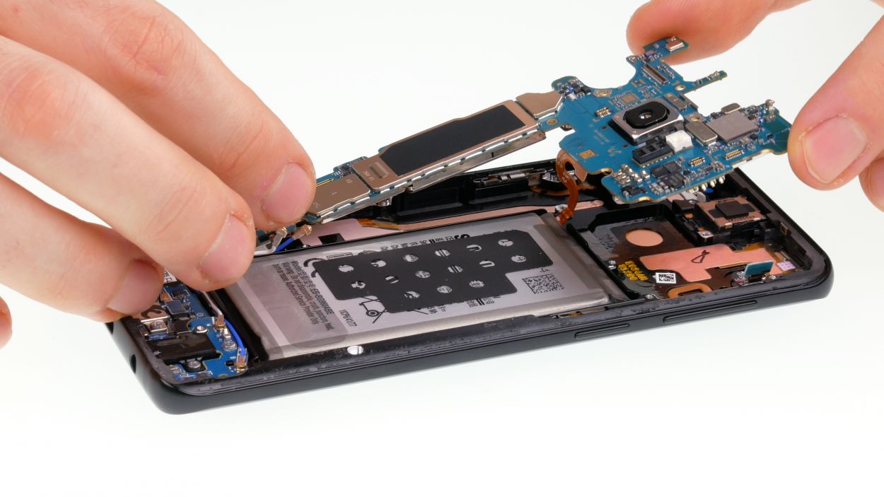
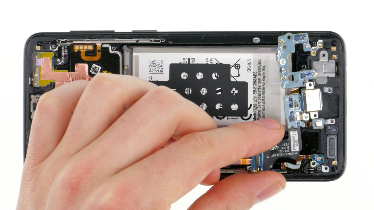
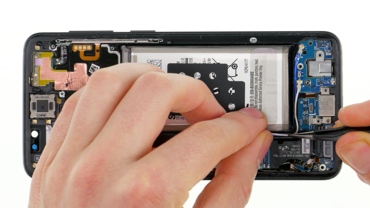
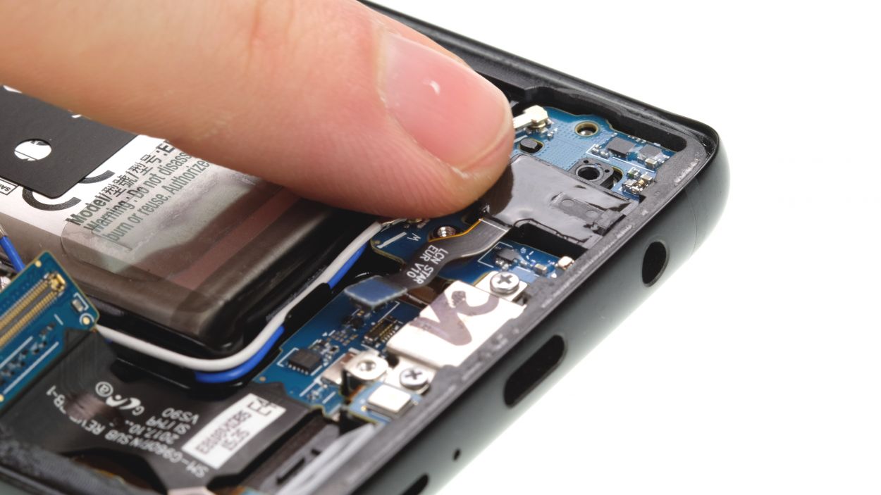
– First things first, let’s get that single screw on the logic board out of the way!
– Before you dive into removing the logic board, just double-check that all connectors are nicely tucked aside and not in a tangled mess.
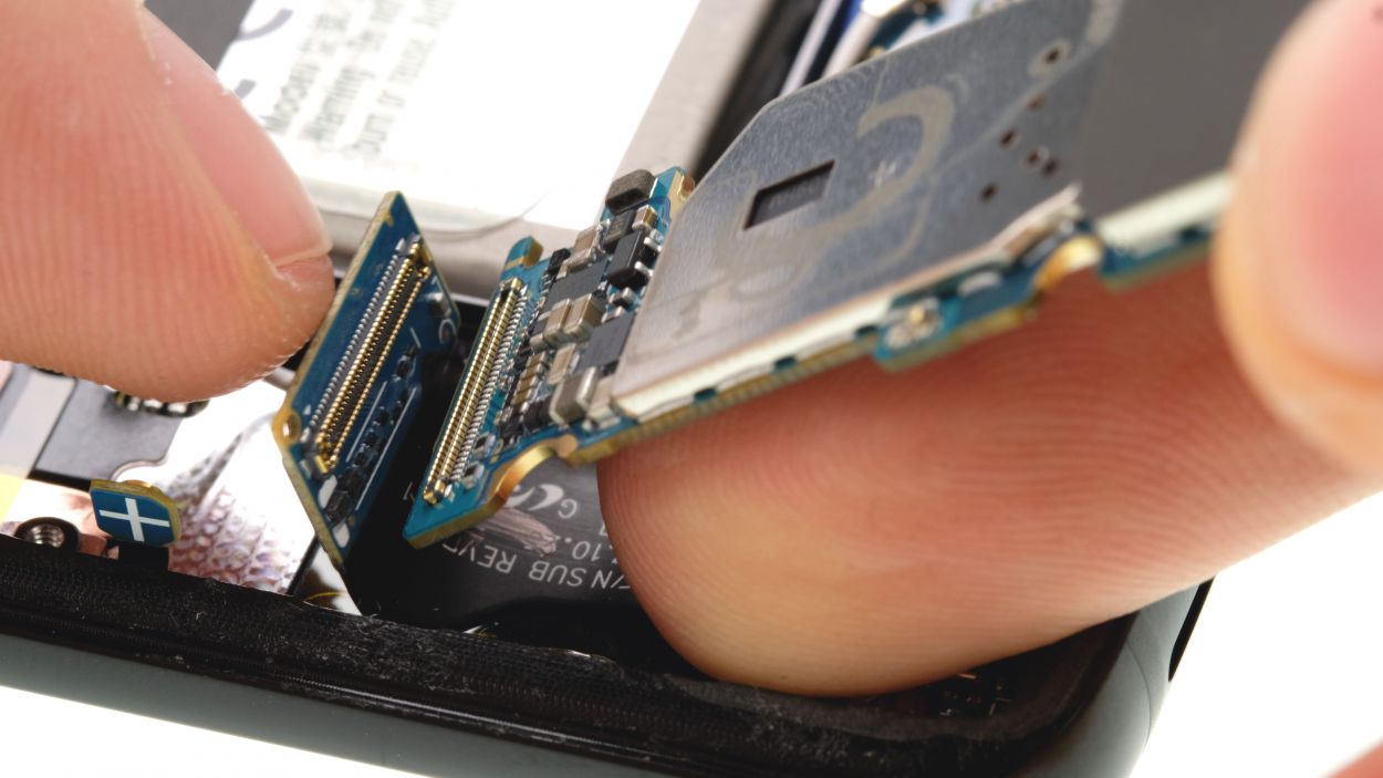
– Now, the logic board is still hanging out with the USB board on the bottom side. Gently lift up the logic board and use a spudger to flick off the connector.
– Once that’s done, feel free to set the logic board aside and give yourself a pat on the back!
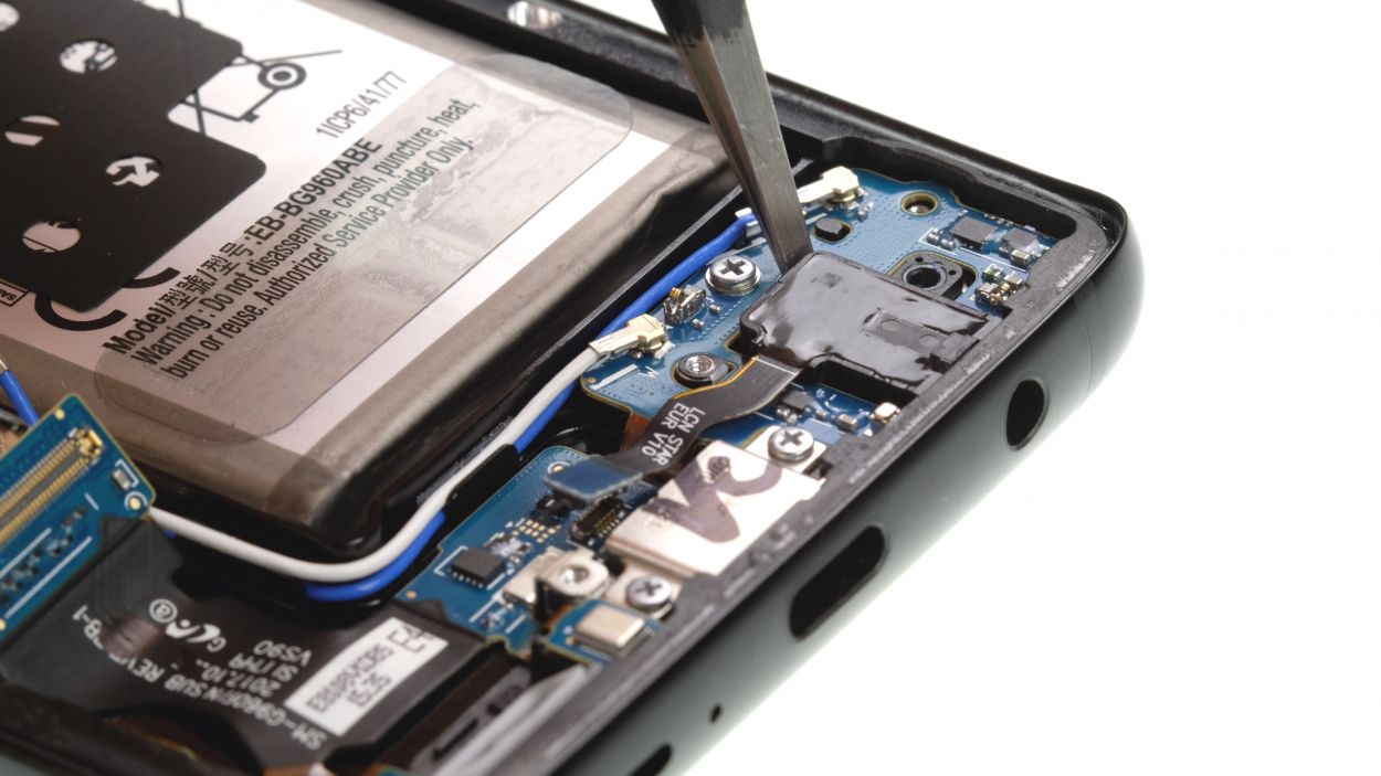
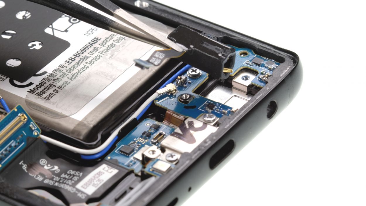
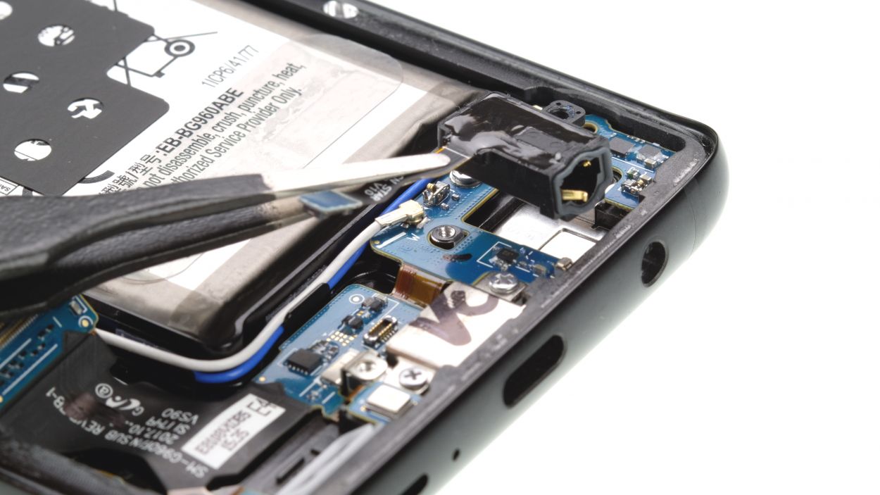
Step 11
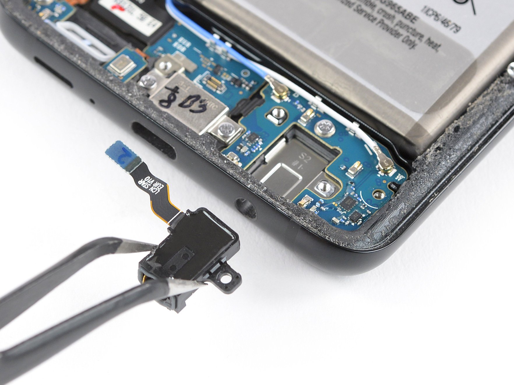
1 × 3.4 mm Phillips
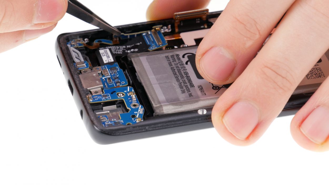
– Take that trusty screwdriver and unscrew the little fella holding the jack snugly in its spot.
– Gently unplug the audio port’s connector from the USB board—it’s time for a little separation!
– Now, carefully lift the audio port out of the case. It’s like giving it a little vacation!
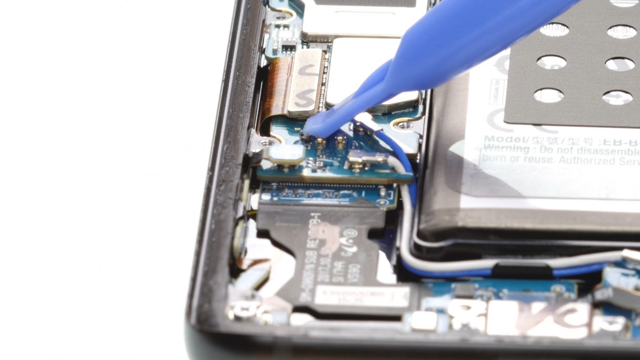
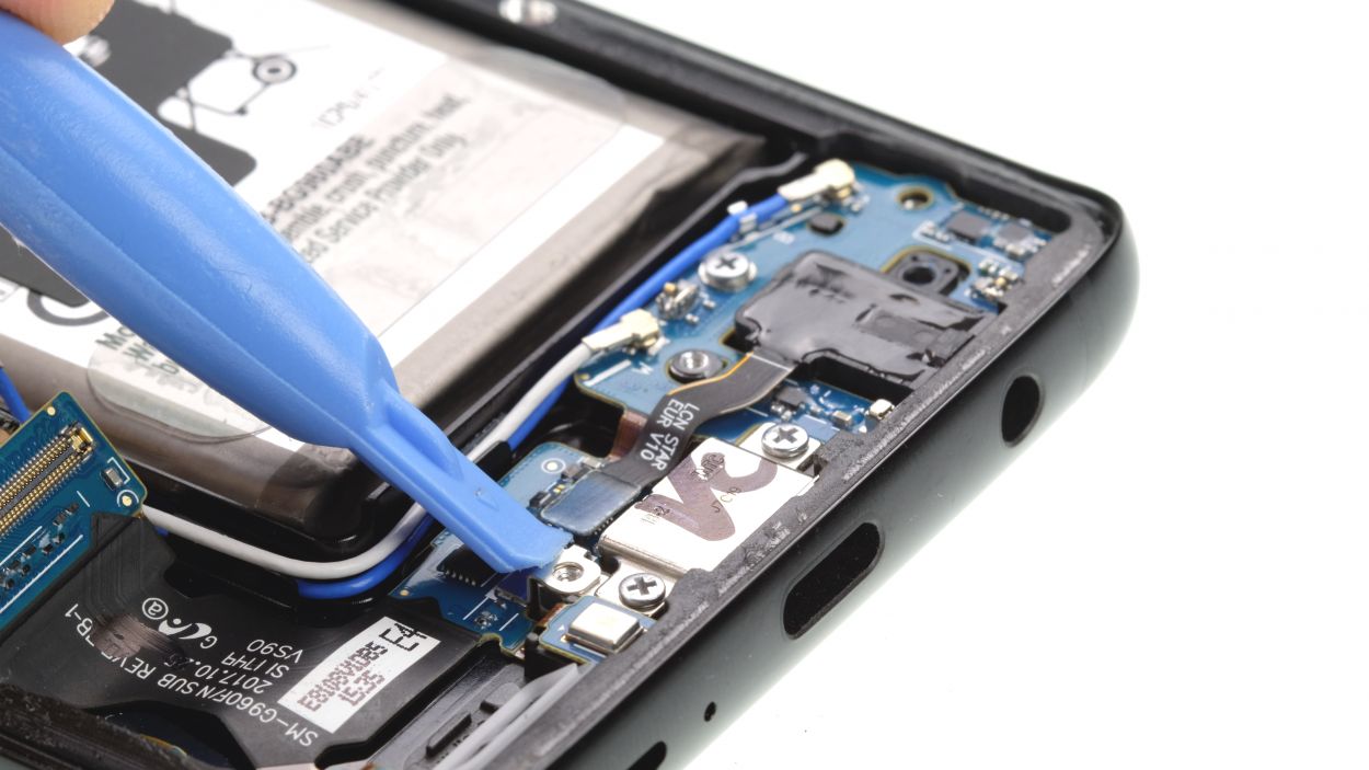
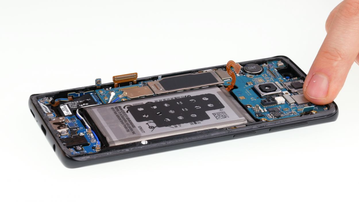
Step 12


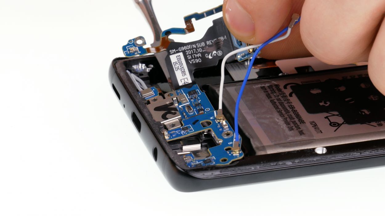
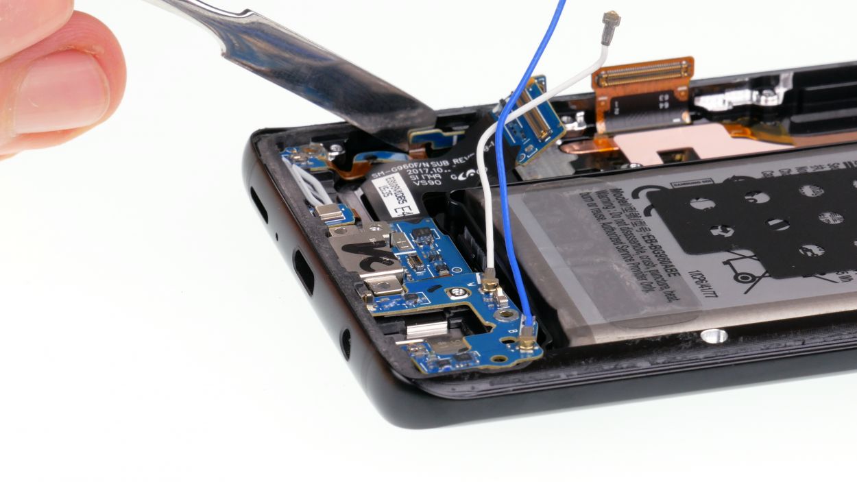
4 × 3.4 mm Phillips
– Time to tackle those USB board screws! Unscrew the remaining ones; they’re all the same length, so no need to stress about sorting them.
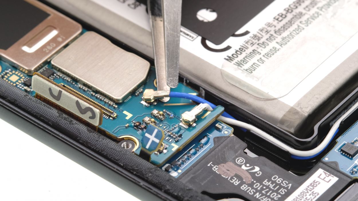
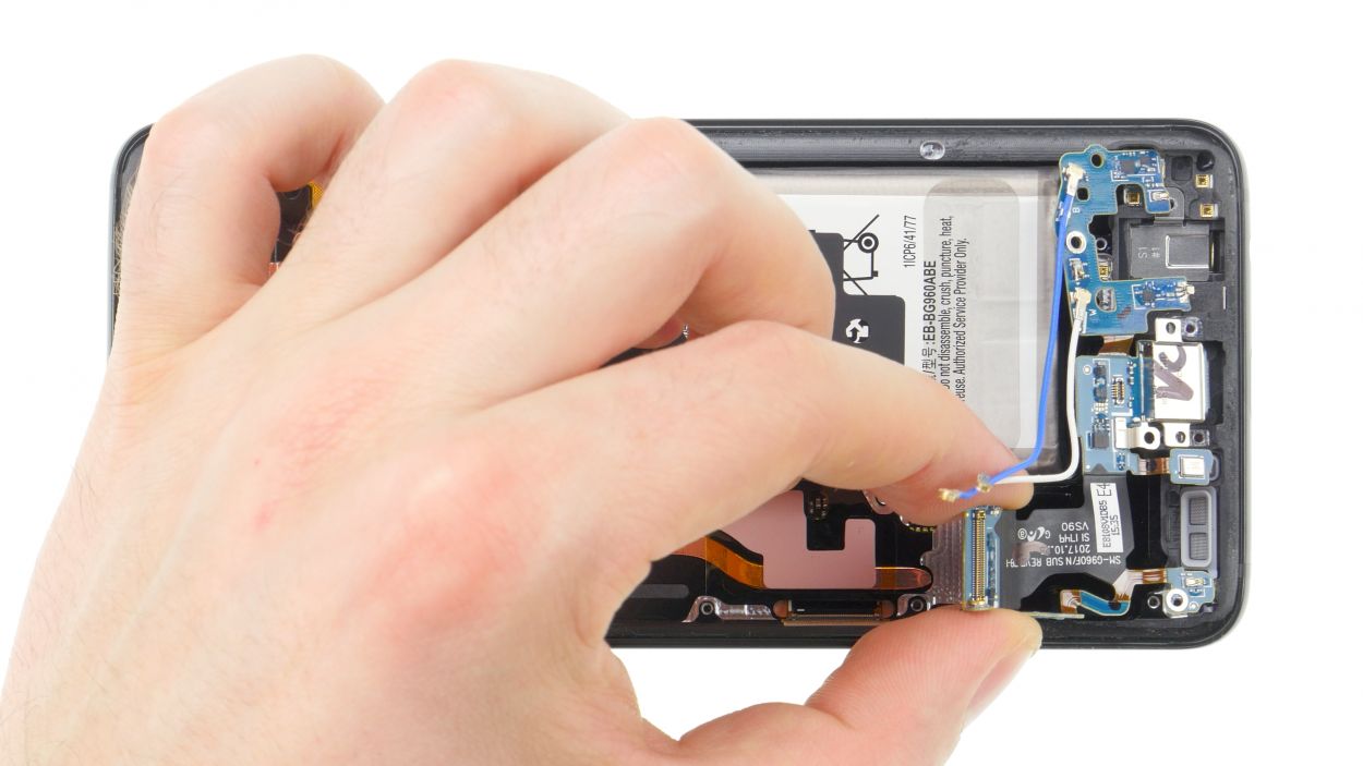
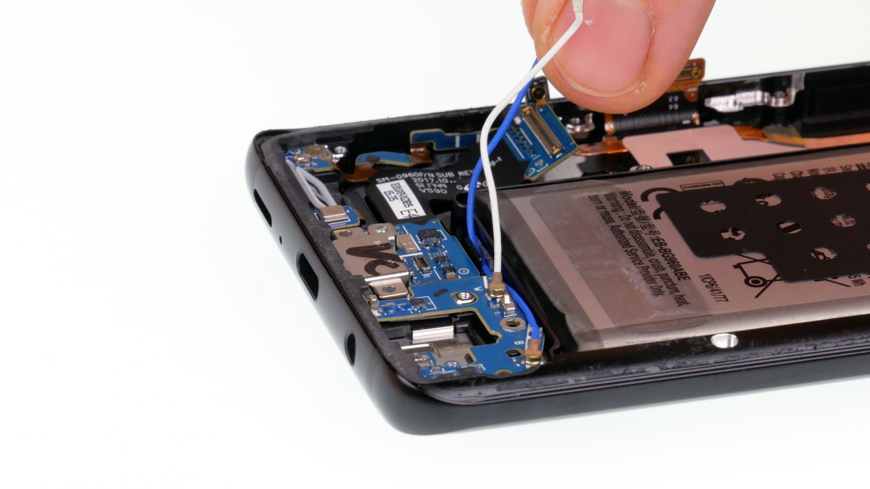
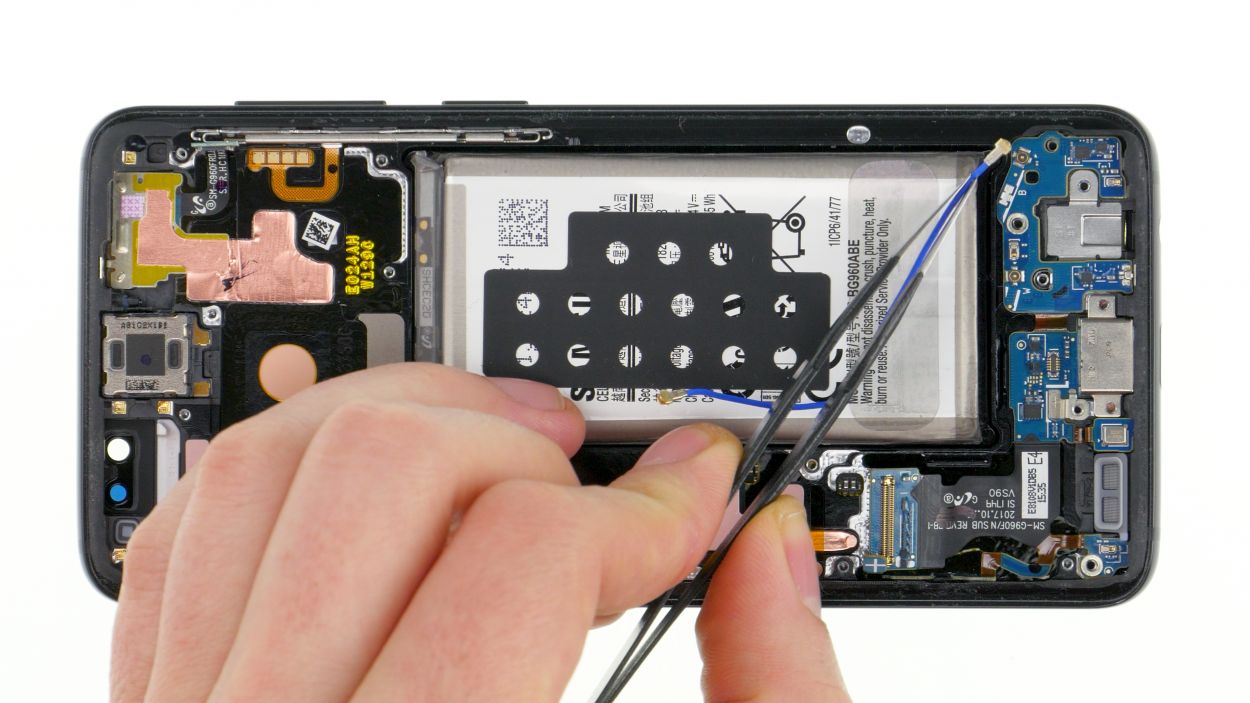
– Next up, gently detach the white and blue antenna cable from its little guide. It’s just a little tug, nothing too wild!
– Now, the USB board is glued to the frame. Grab a spatula and carefully unstick it. Think of it as giving it a little spa treatment.
– Once it’s free, lift the USB board and slowly ease it out with your spatula. Patience is key here!
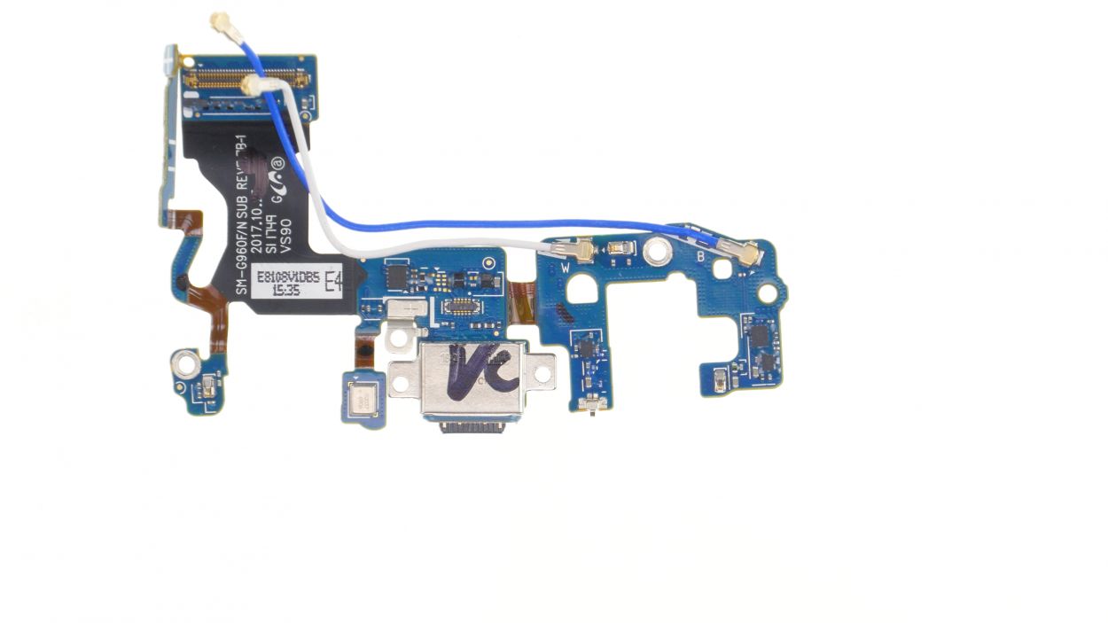
– And voilà! You’ve successfully removed the entire USB board. Great job!
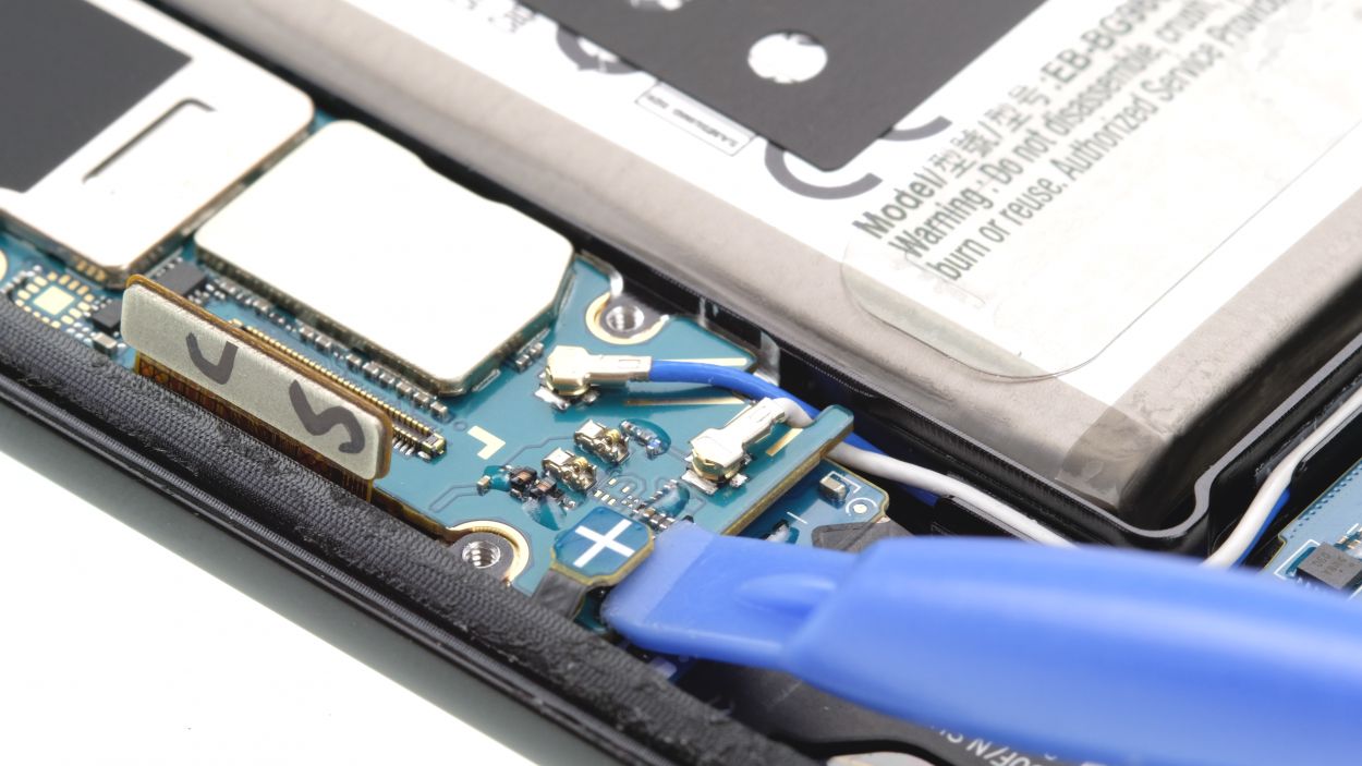
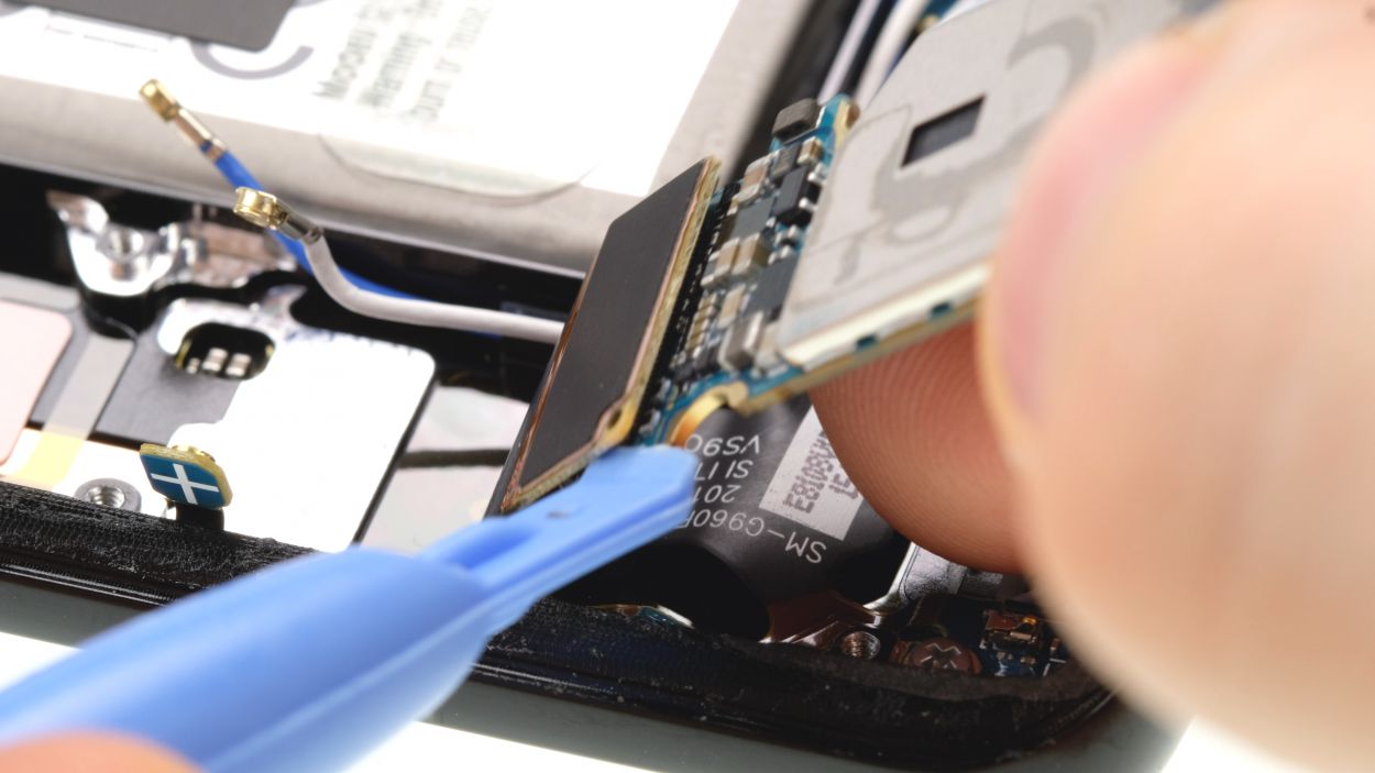
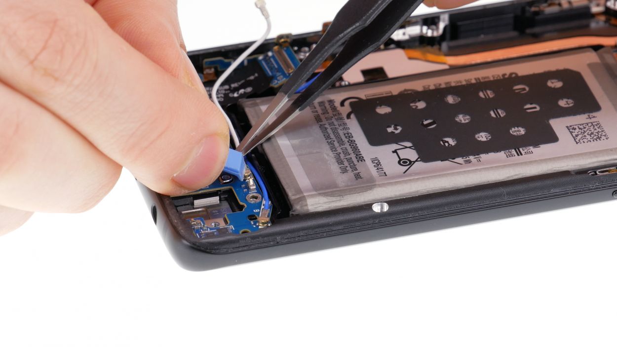
Step 13
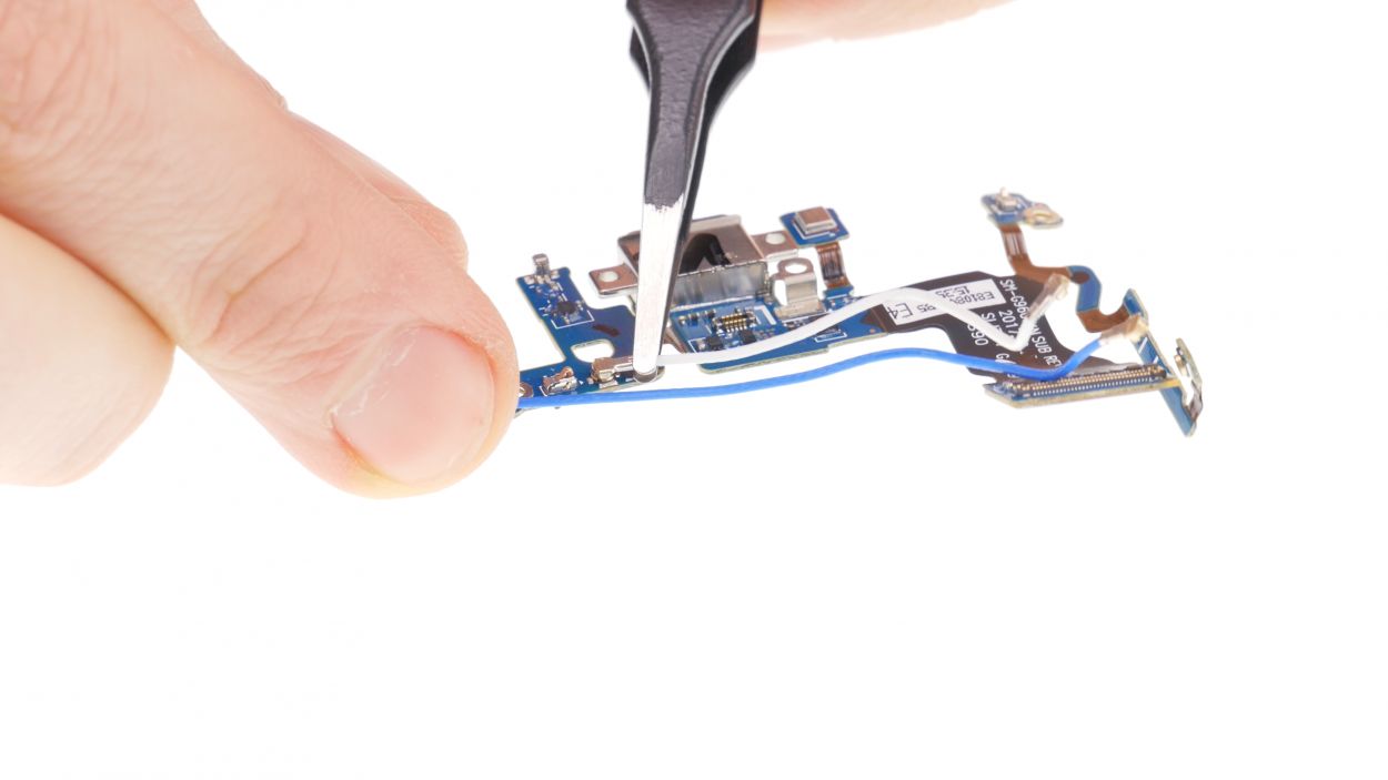
– Carefully grab the plugs with your tweezers and give them a gentle twist to pop them off. You’ve got this!
Step 14
4 × 3.4 mm Phillips
– Get that USB board into the display unit and press it down gently. Ensure all parts are snug.
– Time to stick that flex cable back onto the frame.
– Next, pop those antennas into their guide and connect them to the USB board. Start with the blue one, then move on to the white.
– Now, tighten up those screws on the USB board.
Step 15

1 × 3.4 mm Phillips
– Slide that jack right into the cozy little spot on the bottom edge of the enclosure.
– Grab a screw and secure that jack to the enclosure like a pro.
– Connect the jack’s contact to the PCB and listen for that satisfying click as it locks in place.
Step 16

1 × 3.4 mm Phillips
– Alright, let’s get that logic board snuggled in! First, grab it and plug in the connector at the bottom.
– Gently fold the logic board into its home – nice and easy does it!
– Watch out for those cables; don’t let them get squished!
– Time to bend the antennas and connectors to the side – think of it as a little yoga for your tech.
– Give the logic board a gentle press until you hear that satisfying click. You got this!
– Last step: Secure it with that single screw. You’re a repair rockstar!
Step 17

Antenna plug
– Grab those antenna plugs with your trusty tweezers and give them a little click to lock them in place.
– Next up, let’s connect the display and volume button connectors—just a little click and you’re golden!
– Remember, all connectors should snap into place with a satisfying click. If they’re being stubborn, just unplug and give it another go!
Step 18
If things are feeling a bit jammed up, it might be that the logic board isn’t quite in its happy place. Let’s give it a little nudge!
– Pop that SIM tray back in place!
Step 19
– Pop in the front camera and snap that connector into place!
Step 20
5 × 4.0 mm Phillips
– Now, gently place the speaker back over the USB board, give it a little press to secure it in place, and fasten it with screws to keep everything snug.
– Don’t forget to check that it’s properly latched at the bottom!
Step 22


10 × 4.0 mm Phillips
– Then attach the midframe with the NFC tag.
– Latch it in and press it in all around.
– Then fasten all the screws again.
Step 23
Fingerprint connector
– Alright, before you snap that back cover back on, let’s make sure to reconnect the fingerprint sensor first. Can’t have your fancy gadget going rogue, can we?
– Now, gently place the back cover over your device and lift it just a tad to get to that connector. Keep it steady and close to the device – we want to avoid any drama!
– Grab a plastic tool, like a spudger, to reach the connector and give it a little push down. If you’re feeling adventurous, ESD tweezers or an ESD spudger work great too! Just remember to take a deep breath and keep those hands steady.
Step 24

Hey there! Just a friendly reminder: once you pop open your smartphone, its water resistance isn’t quite what it used to be. So, let’s keep it dry and safe out there!
– Before you pop that back cover back on, take a peek at the glue. It should be spread out nice and even on the back cover. Feel free to tidy up any extra glue that might be hanging around.
– Next up, give the back cover a good press down.
– Now, let’s heat things up a bit! Warm the back cover again to help the glue stick like it means it.
– While the glue is cooling, you can give the back cover a gentle press with your fingers. Just a little encouragement goes a long way!