Samsung Galaxy S9 Sensor Cable Replacement Guide: Step-by-Step
Duration: 60 min.
Steps: 21 Steps
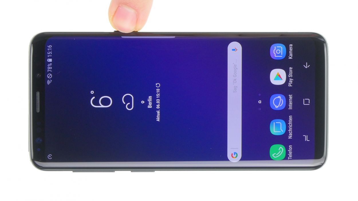
In this guide, we’re here to help you swap out a faulty sensor in your Samsung Galaxy S9. This repair is a must if your screen refuses to turn off while you’re chatting on the phone, or if the LED indicator has decided to take a break. Let’s get your device back in action!
Step 1

Tap the little Play button in the top right corner of the image to watch a video for each step. It’s a great way to see the process in action!
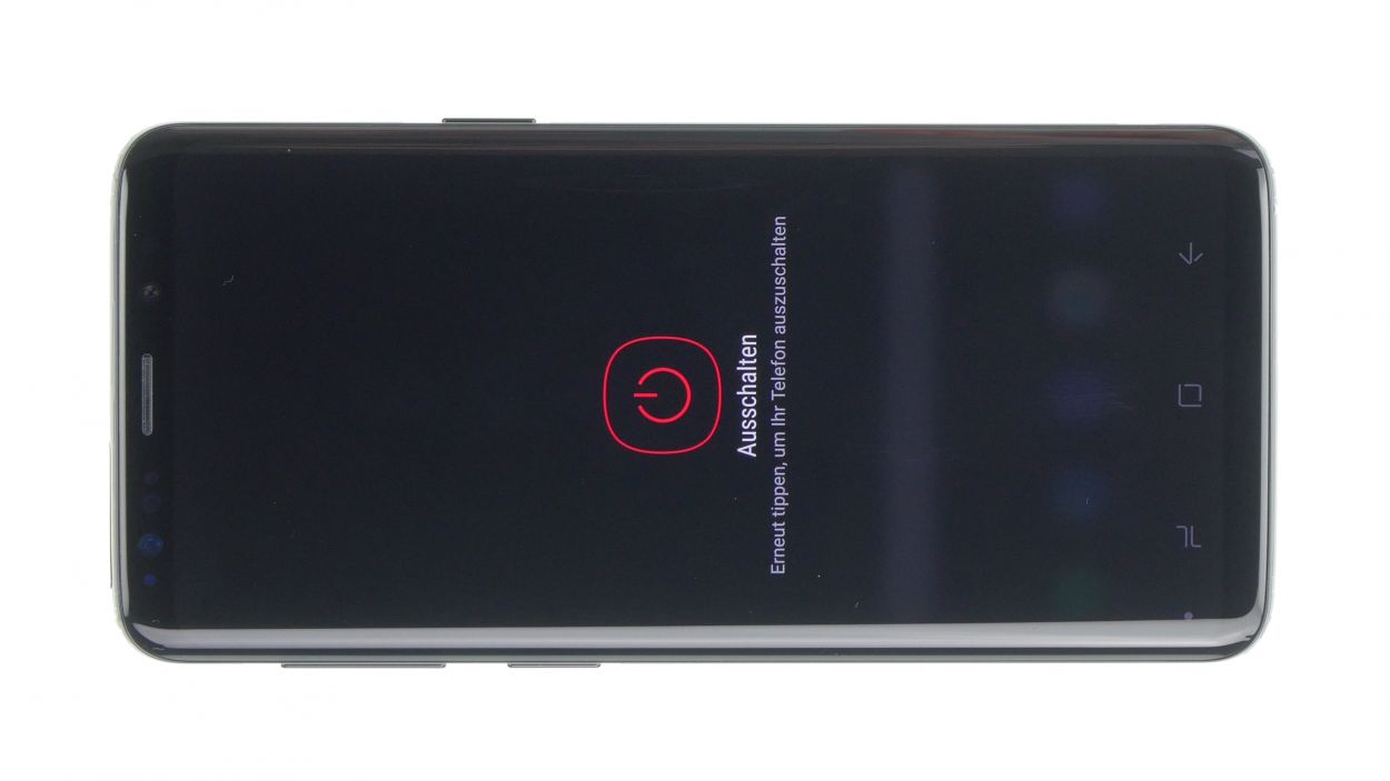
– First things first, let’s power down your device! Just press and hold that power button until you see the ‘Power off’ option pop up.
– Now, give it a little tap with your finger to confirm you want to shut it down, and then sit back and relax while the screen goes dark.
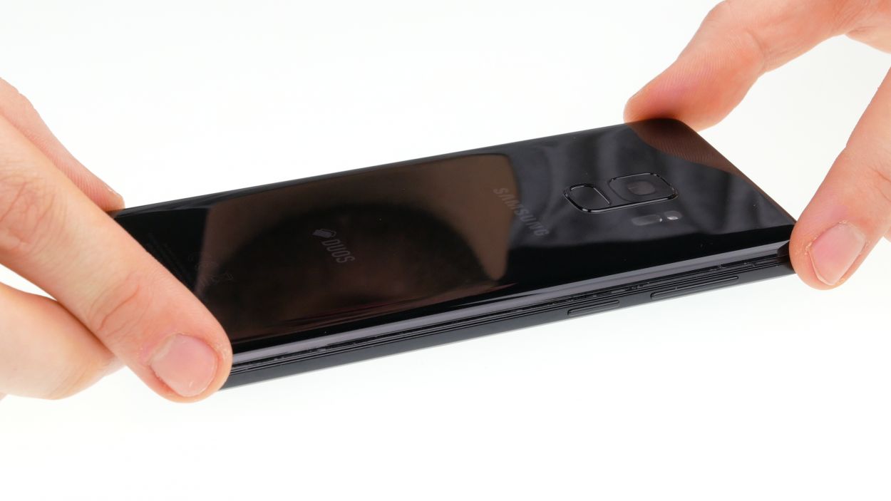
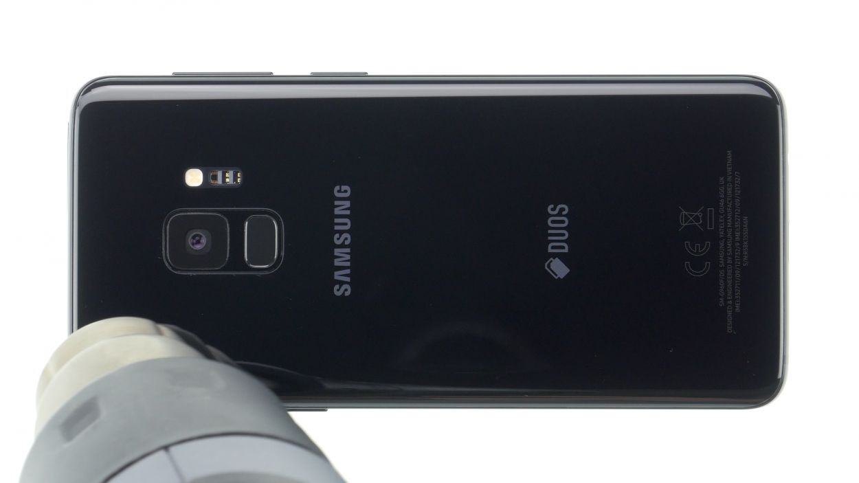
Step 2

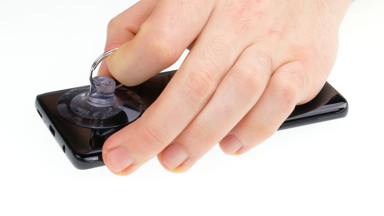

– Warm up the area where you’re starting, then stick a suction cup on the bottom edge of the back cover.
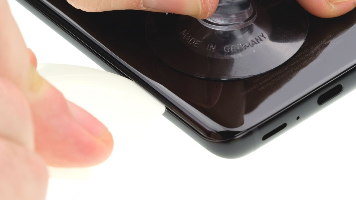
– Slide a flat tool gently between the back cover and the frame while pulling on the suction cup.
Hey there! Just a friendly reminder to handle that back cover with care – it’s a bit fragile and can crack easily. If you find it stubborn, feel free to warm it up a few times and give it another go. Removing the back cover might take a little while, so take your time and work gently to keep everything intact. Remember, patience is key!
The iPlastix is crafted from plastic, ensuring it won’t leave any scratches on your device. However, it’s a bit on the soft side, which can make inserting it a little tricky. Just take your time, and you’ll be all set!
Tools Used
- heat gun to heat parts that are glued on so they’re easier to remove.
In most cases, you can also use a hairdryer.” rel=”noopener”>Heat gun - screen and the frame. The practical iFlex is made of stainless steel and sits comfortably in the hand. This makes it the perfect assistant for every smartphone repair.” rel=”noopener”>iFlex Opening Tool
- VAKUPLASTIC Suction Cup
Step 3

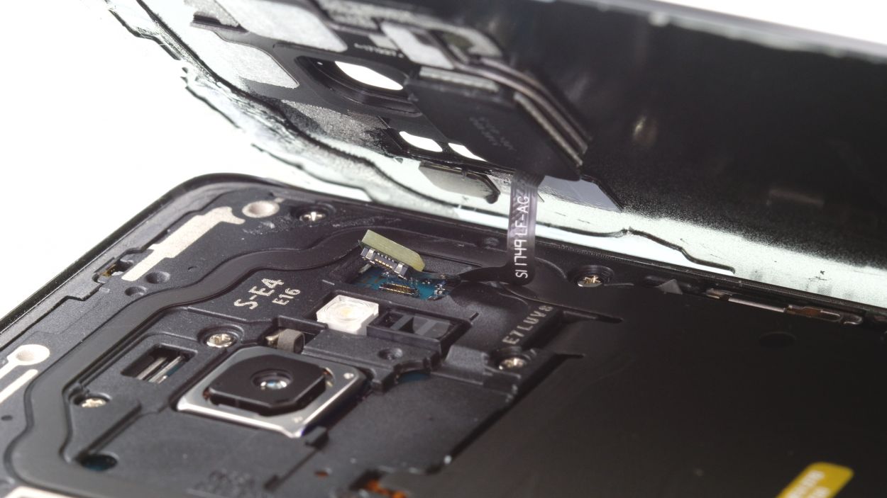
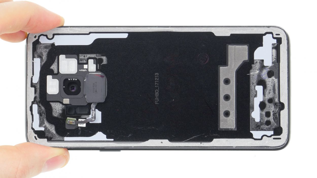
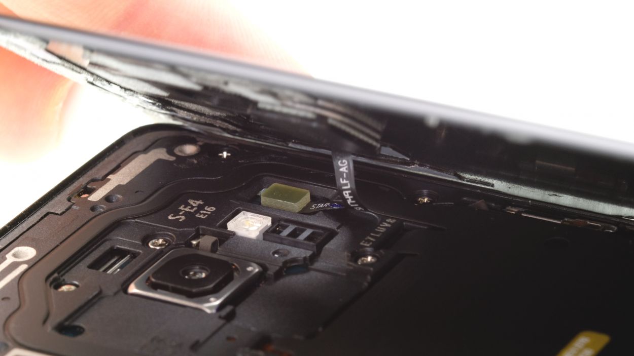
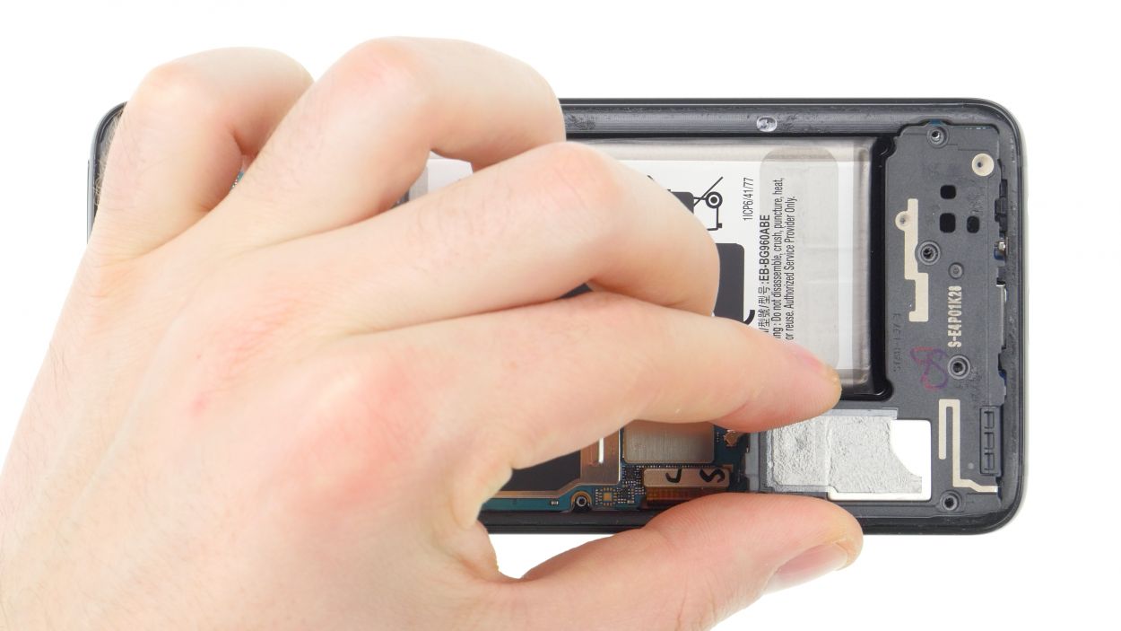
– Once you’ve popped off the back cover, gently lift it up and use that trusty spudger to disconnect the fingerprint sensor. You’ve got this!
– Now, go ahead and fully remove the back cover and set it aside for now. You’re making great progress!
Tools Used
Step 4
10 × 4.0 mm Phillips
This phone only has two types of screws to deal with. If you find any screws playing hard to get, a trusty pair of tweezers can lend a hand!
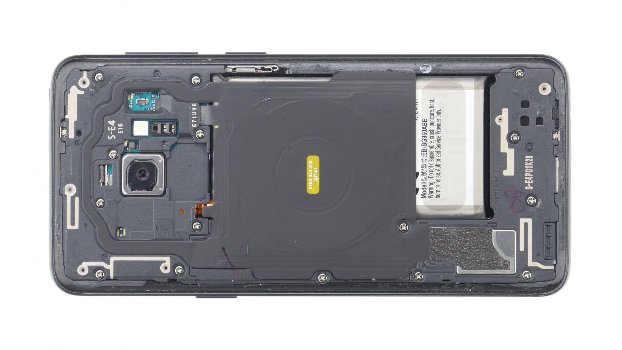
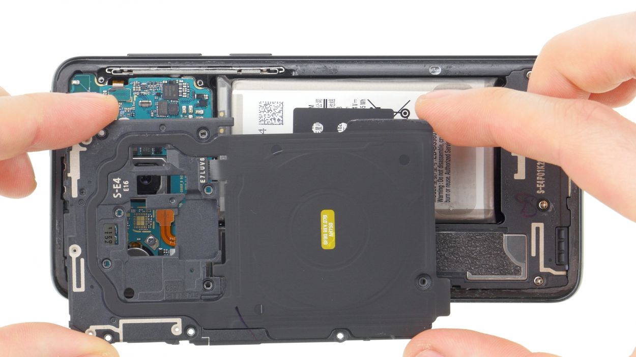
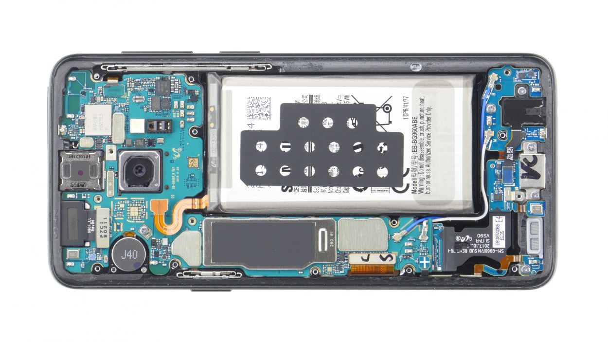
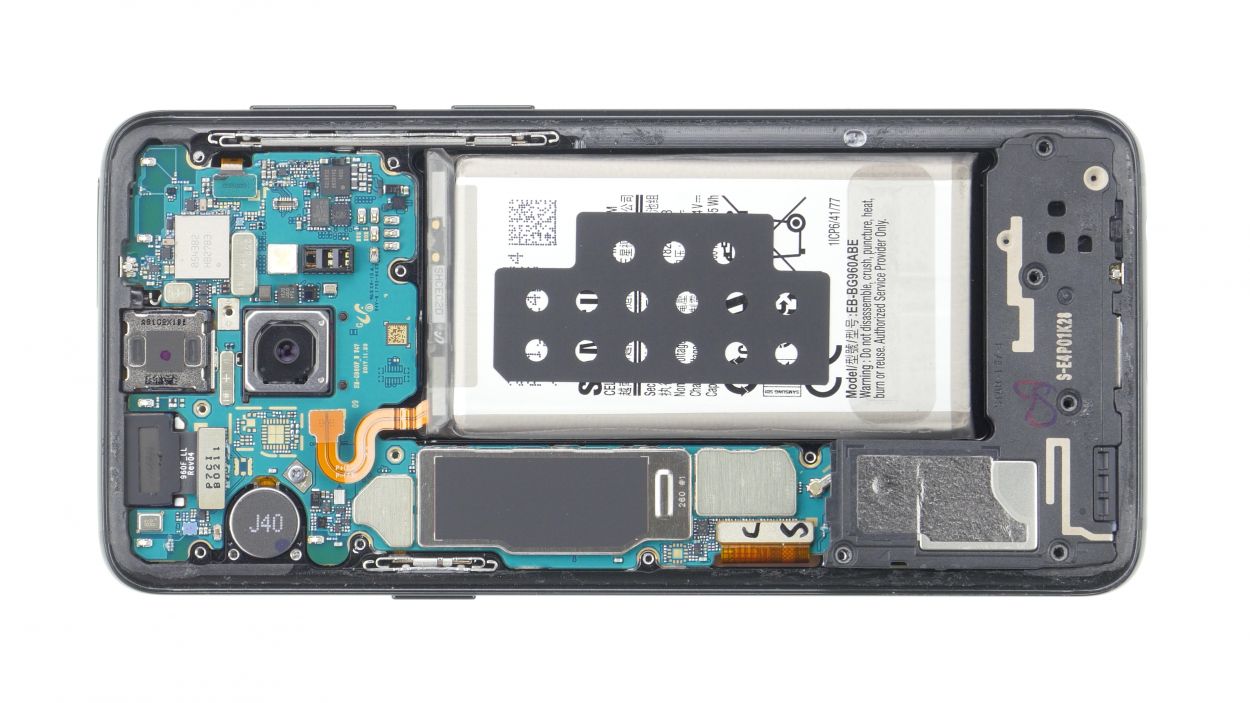
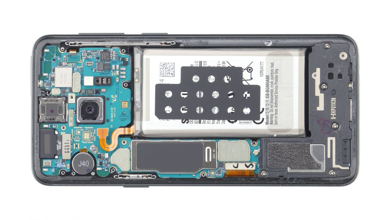
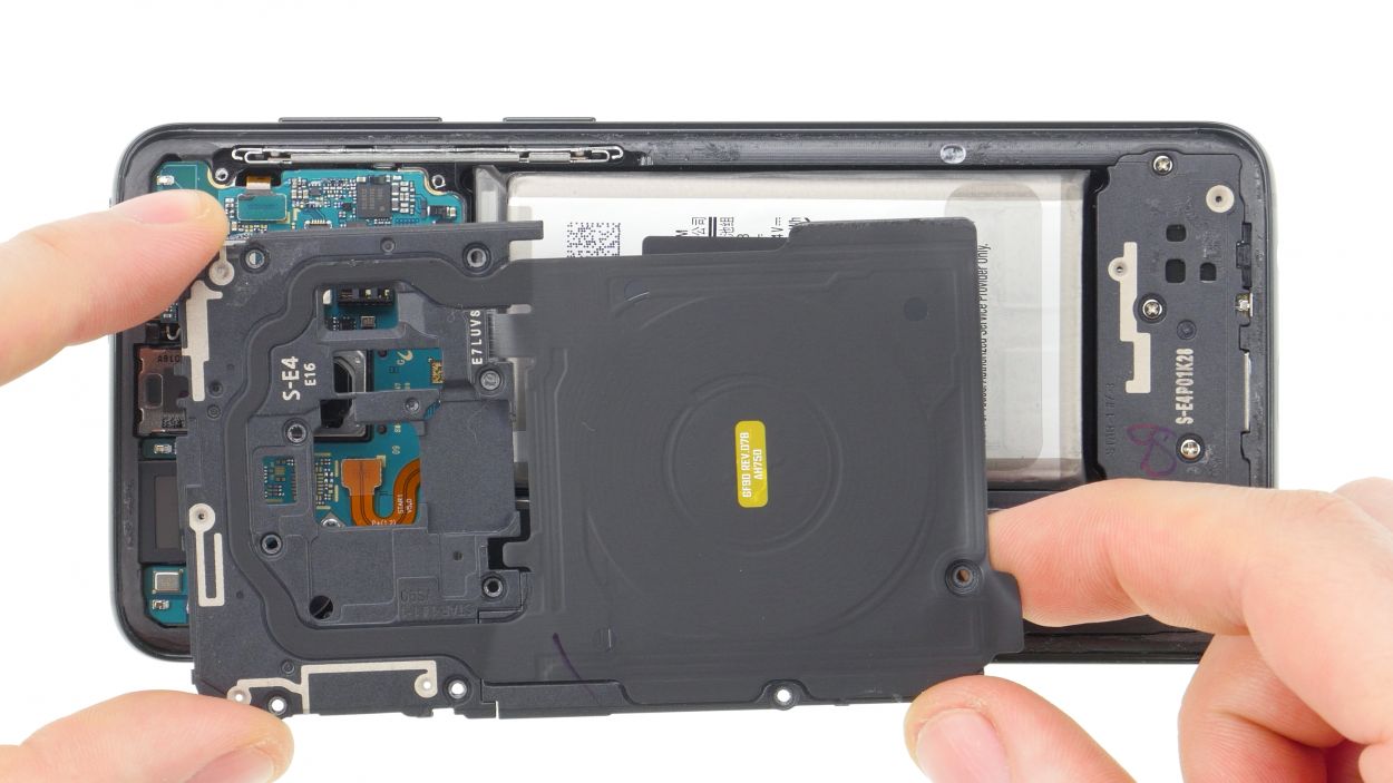
– The logic board cover with the NFC tag is latched in at the top.
– Pry it up a little and then take it out.
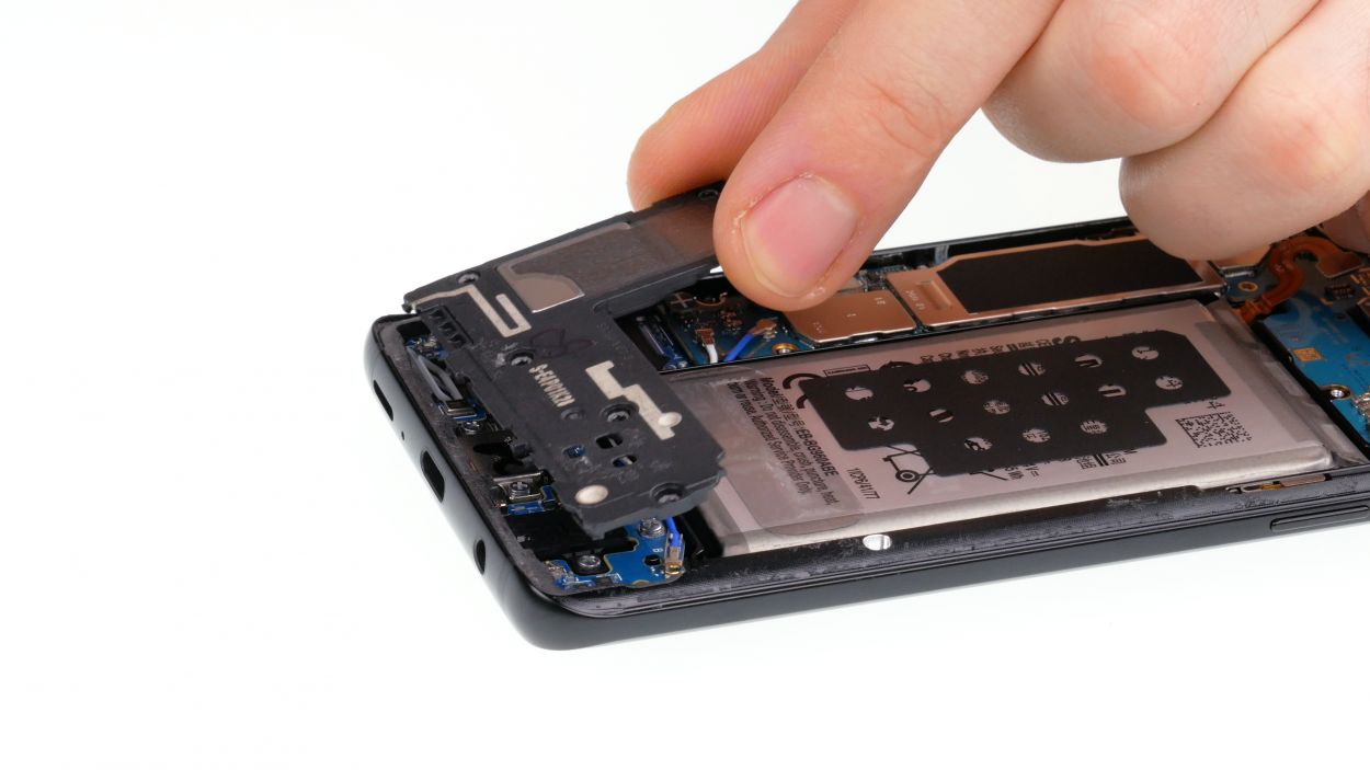
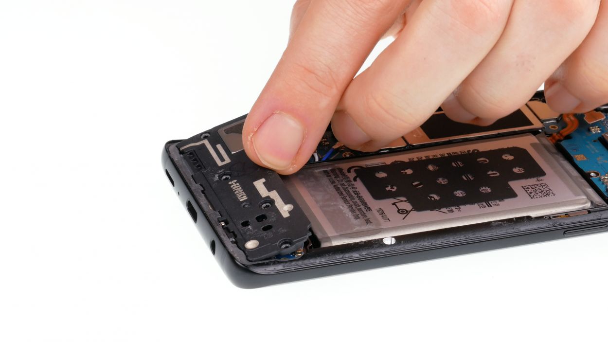
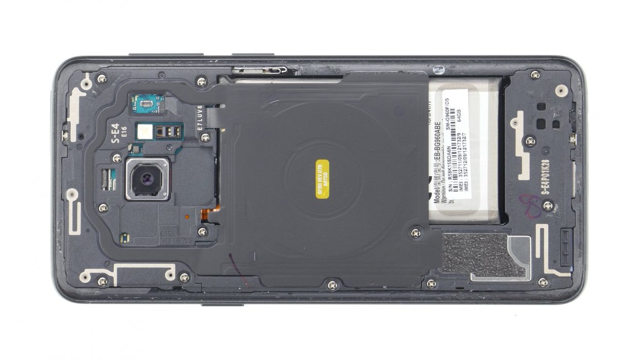
Step 6

5 × 4.0 mm Phillips
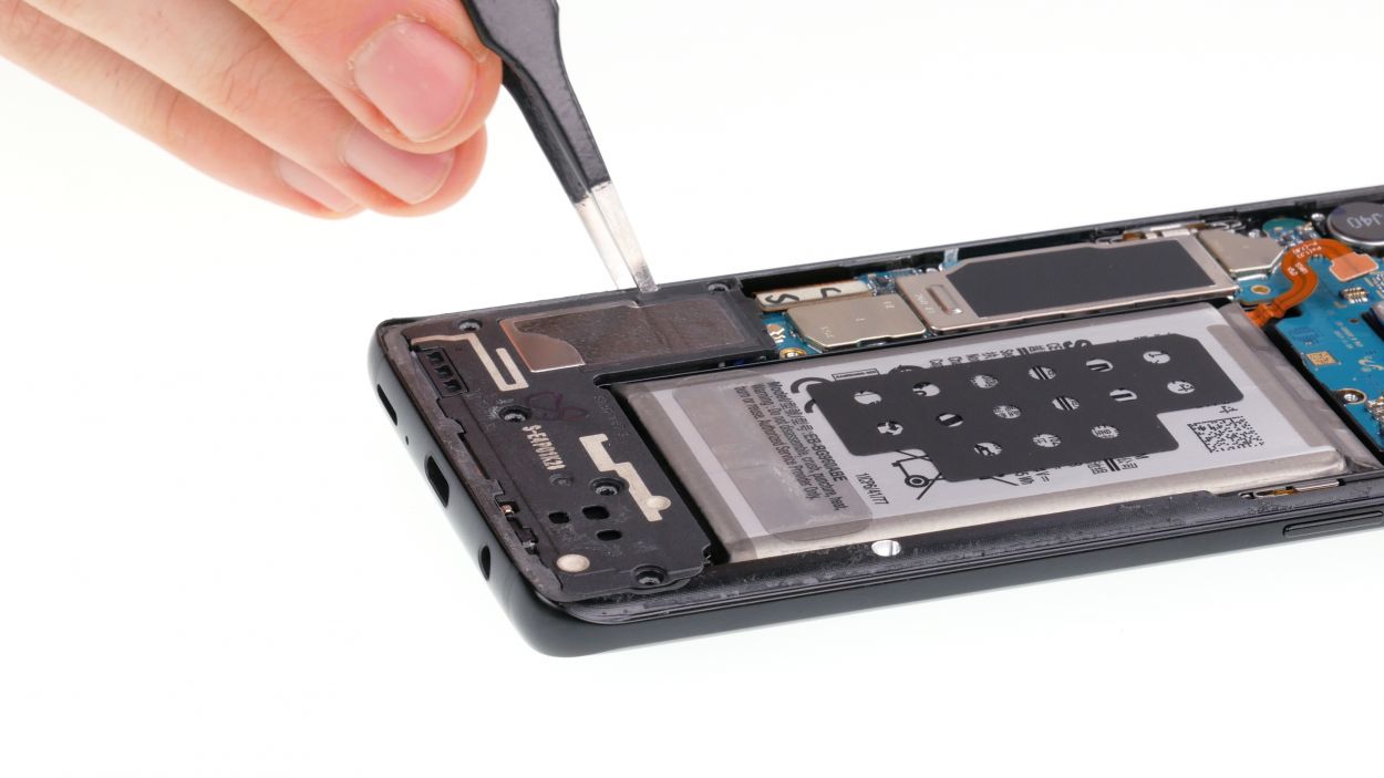
– Gently lift the speaker with your trusty tweezers and then take it out with care.
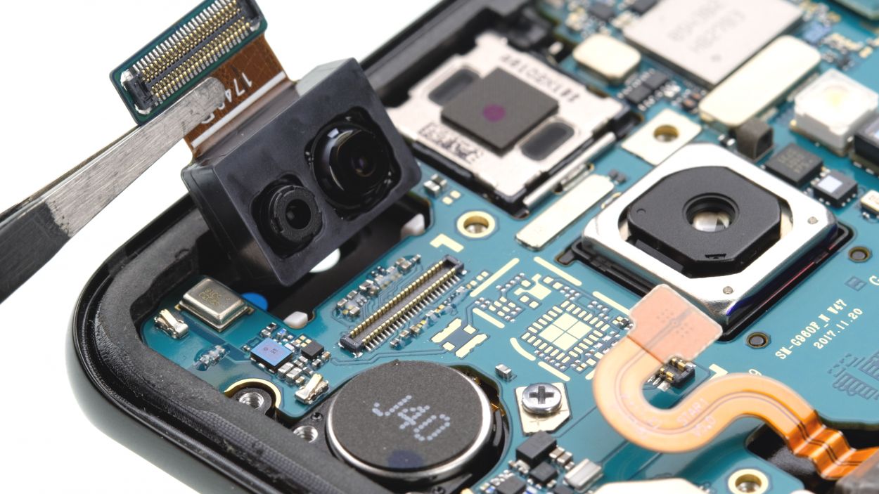
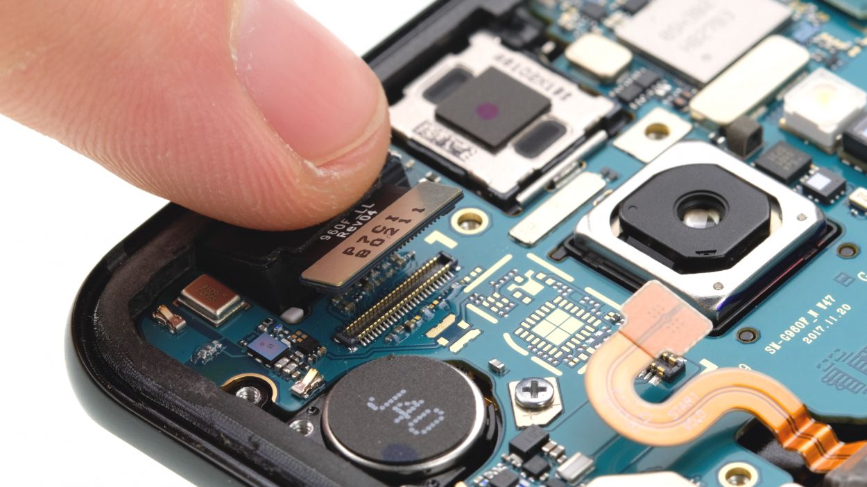
Step 7
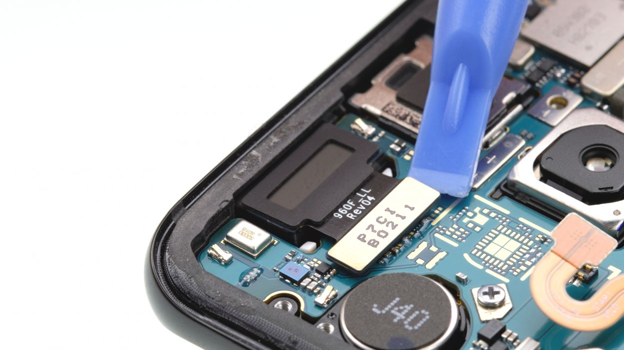

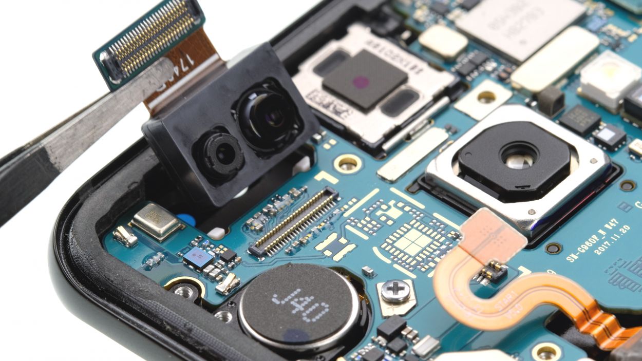
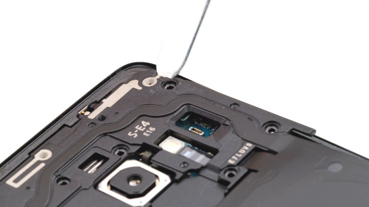
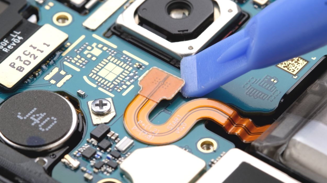
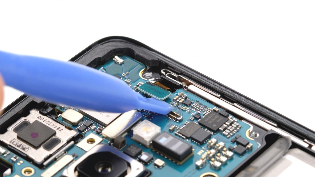
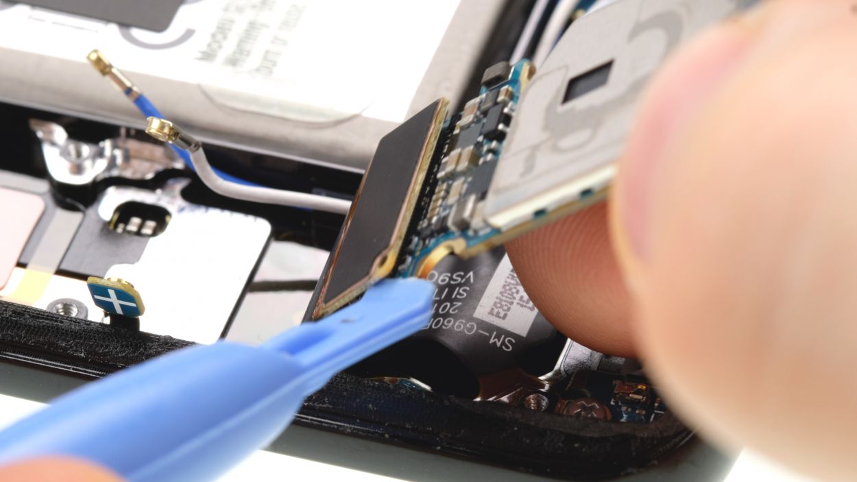
– First up, grab your trusty spudger and gently disconnect that front camera connector. You’ve got this!
– Next, give it a little nudge from the side that’s free of any pesky PCB components. Easy peasy!
– Finally, pop that camera out of its cozy holder. You’re almost there!

Step 9

Antenna Plug
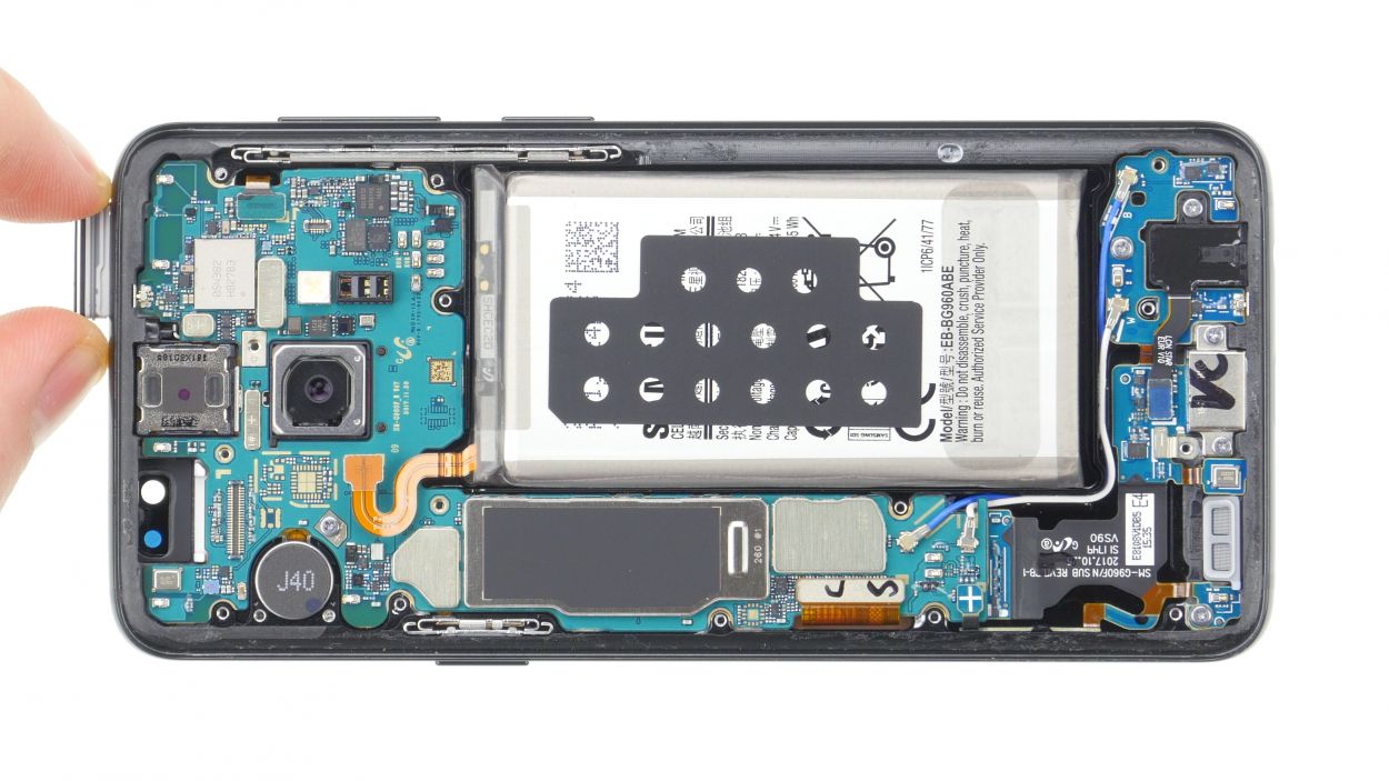
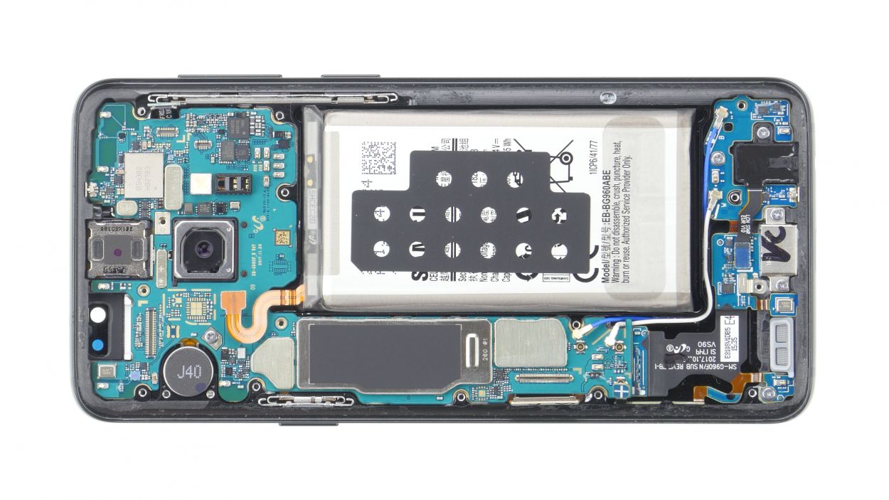
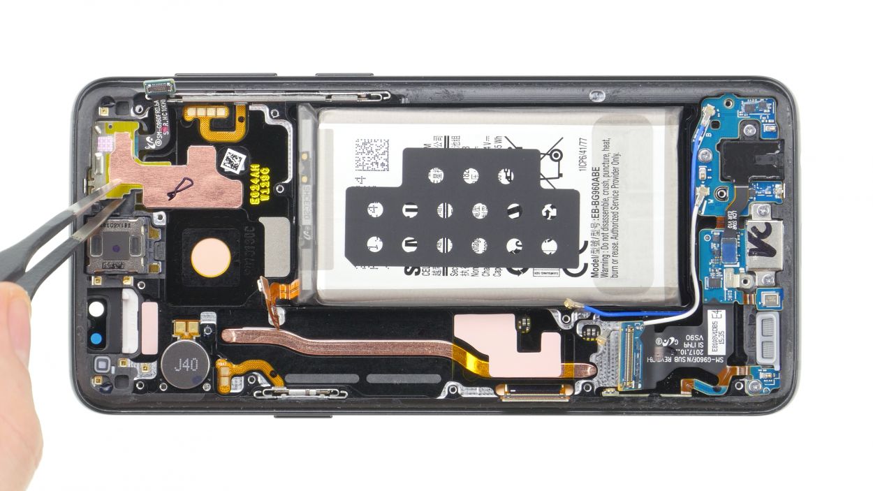
– First up, let’s unplug those various connectors from the logic board. Easy peasy!
– Gently twist the spudger – remember, it’s not a crowbar! We want to keep that logic board happy.
– Watch out for those tiny components next to the connectors; they can be a bit fragile.
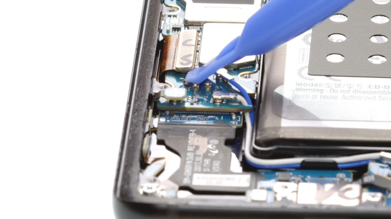
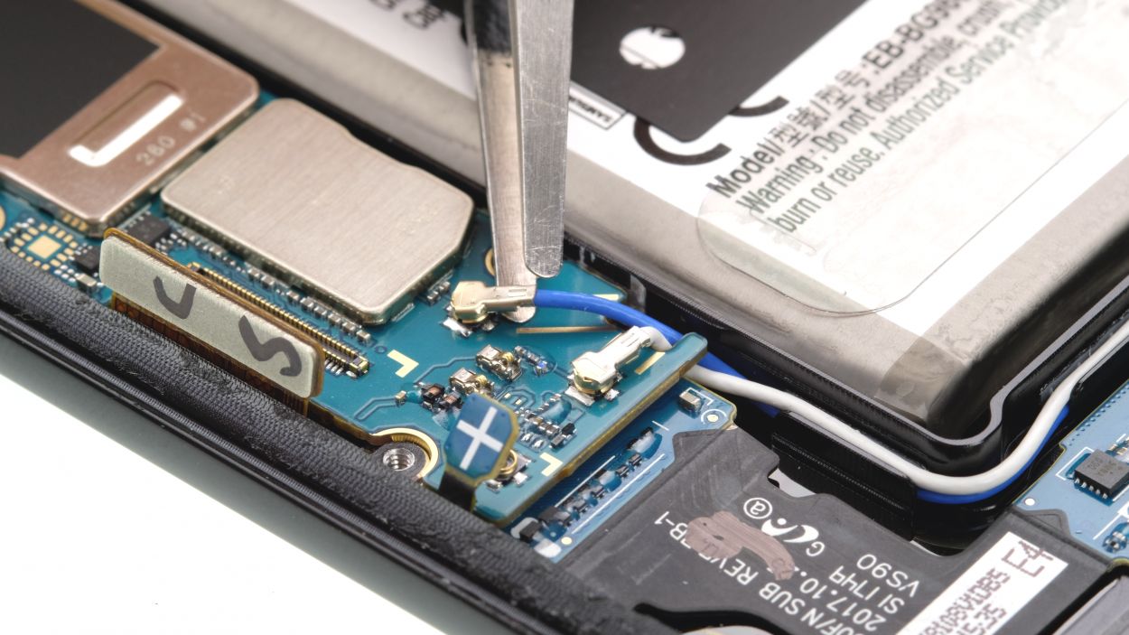
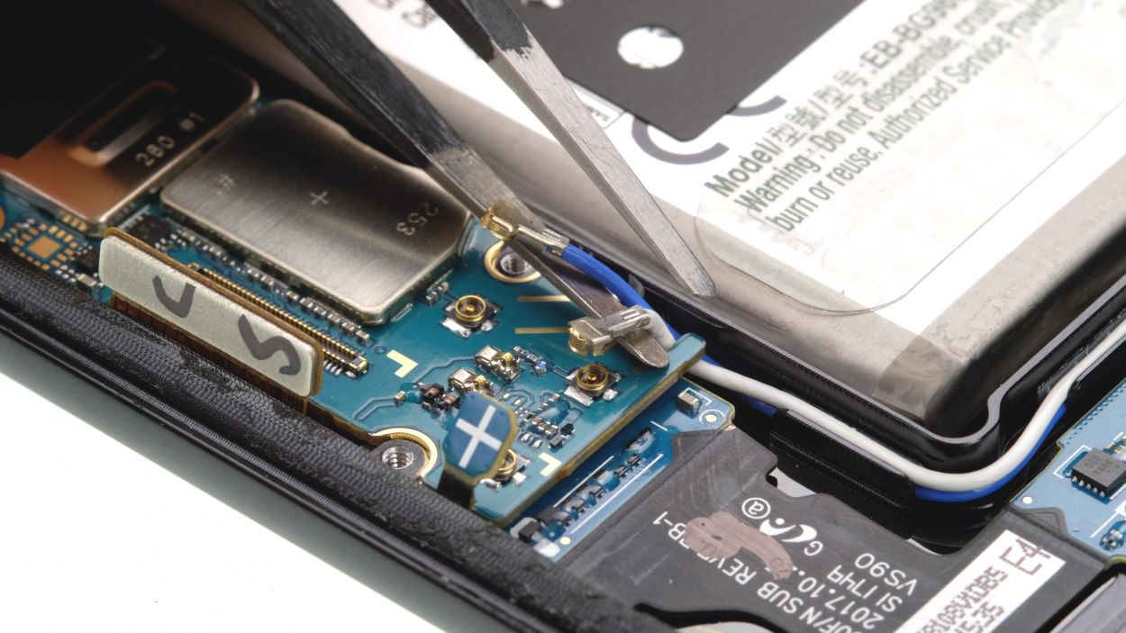
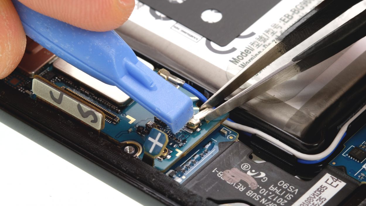
– Next, it’s time to disconnect the button plugs from the antenna cables. You’ve got this!
– Use your tweezers to grab the cable, but steer clear of the plug itself. We want to be gentle.
– Now, give that plug a twist with the tweezers to disconnect it. Smooth moves!
Step 10
1 × 3.4 mm Phillips
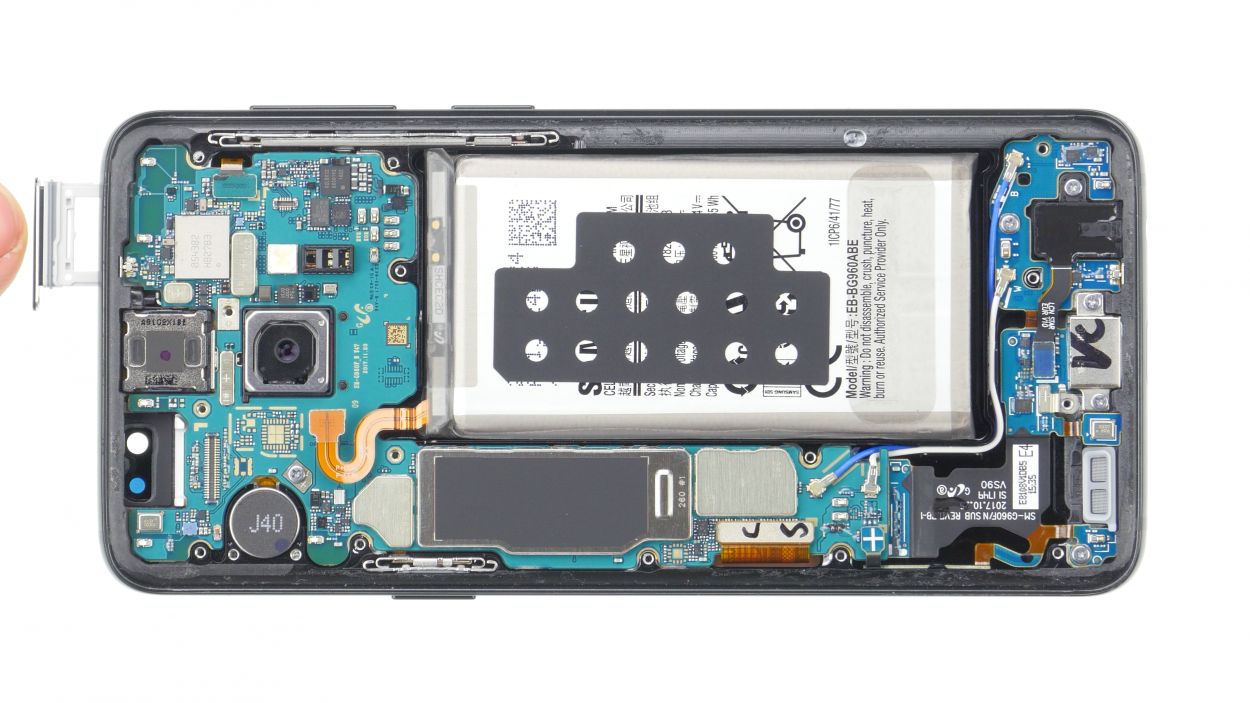
Hey there! Just a heads-up: there’s a tiny plastic pin hanging out in the SIM tray opening. Keep an eye on it so it doesn’t escape on you!
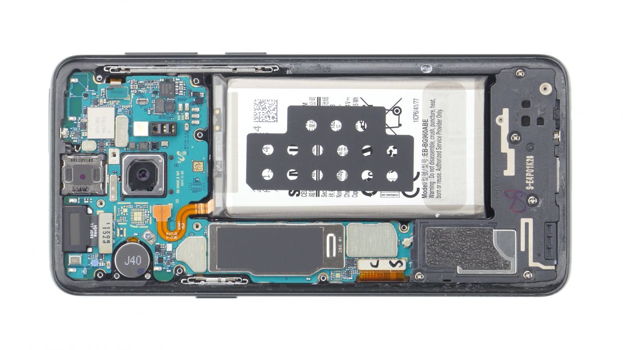
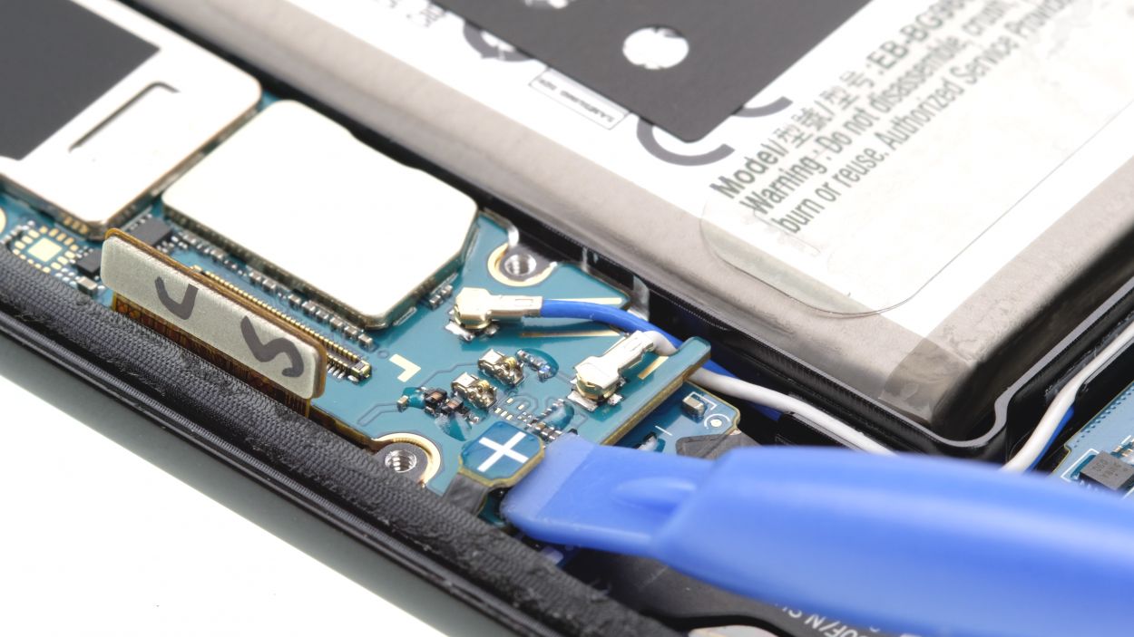
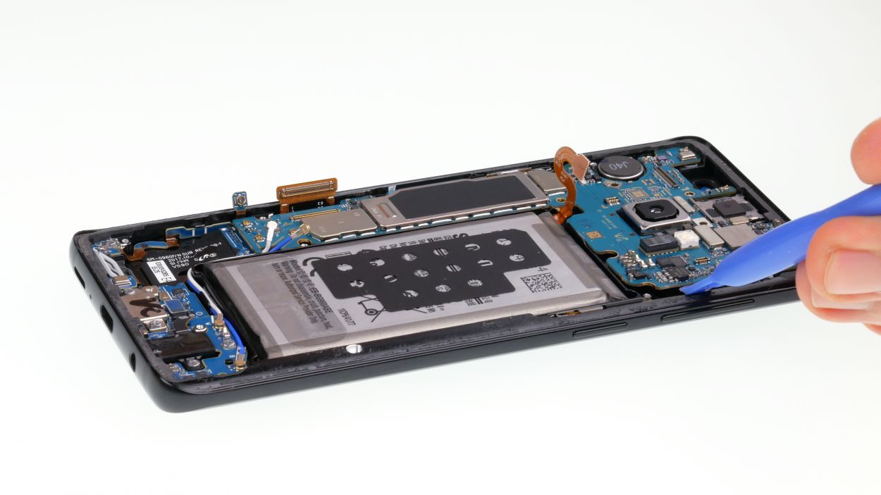
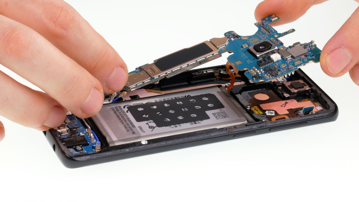
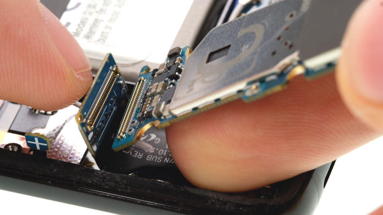
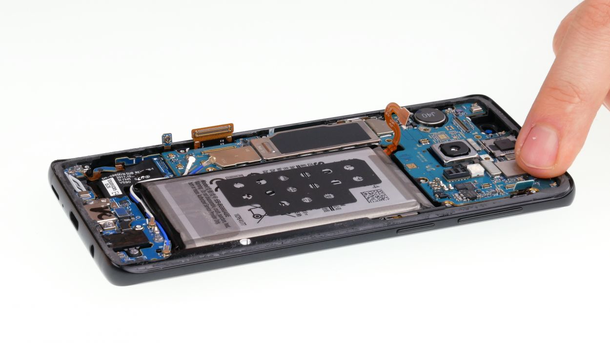
– First, let’s tackle that single screw on the logic board—go ahead and remove it!
– Before you lift out the logic board, make sure all connectors are pushed aside so they don’t get tangled up.
– The logic board is still cozy with the USB board on its bottom side. Gently fold it up and use a spudger to pop off the connector.
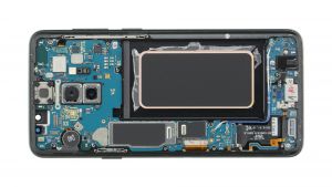
– Now, you can set the logic board aside and give yourself a pat on the back!
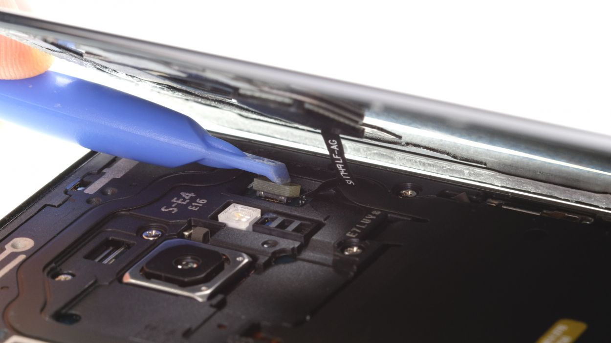
Step 11
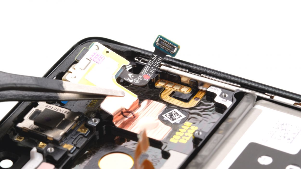
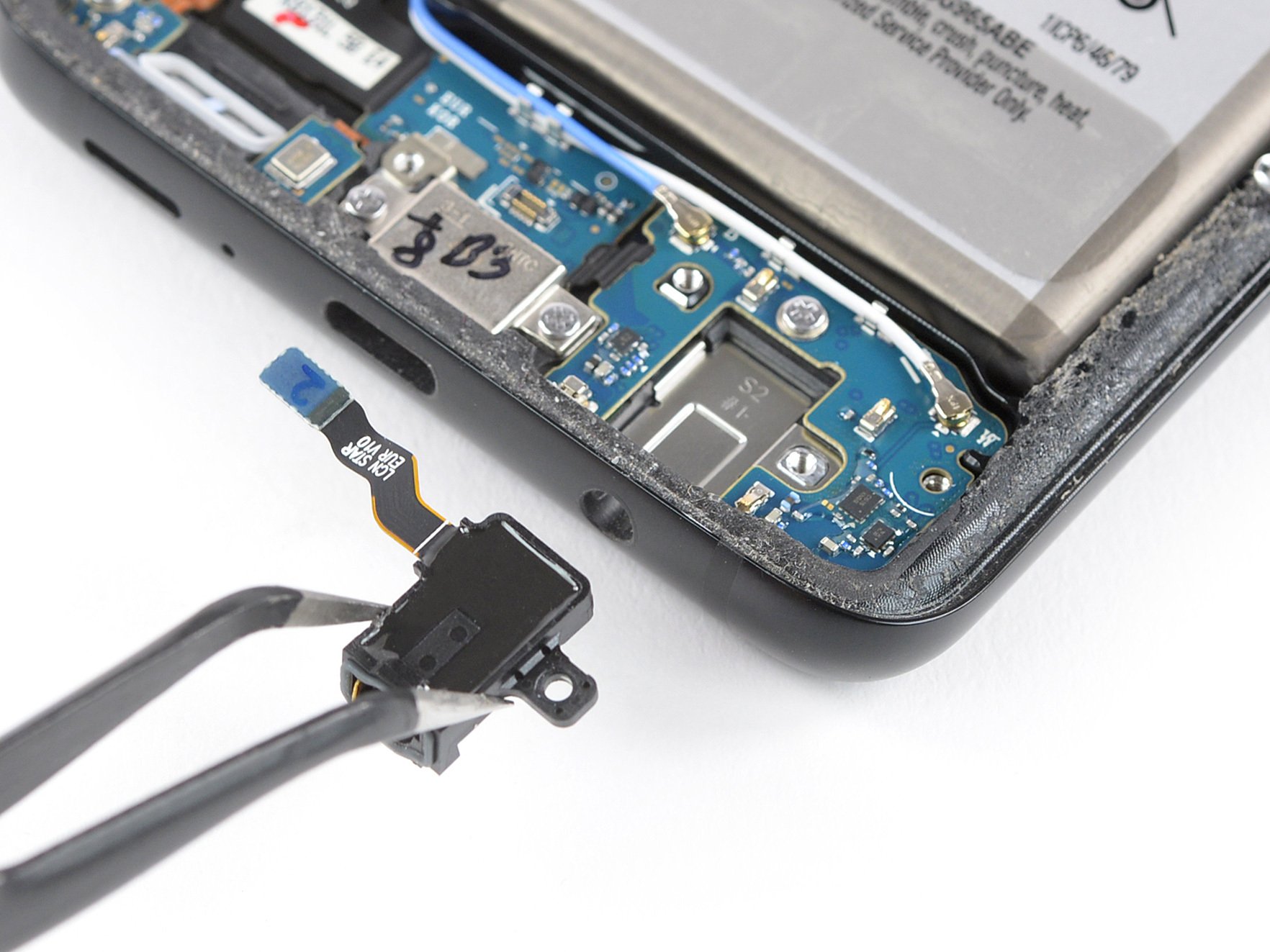
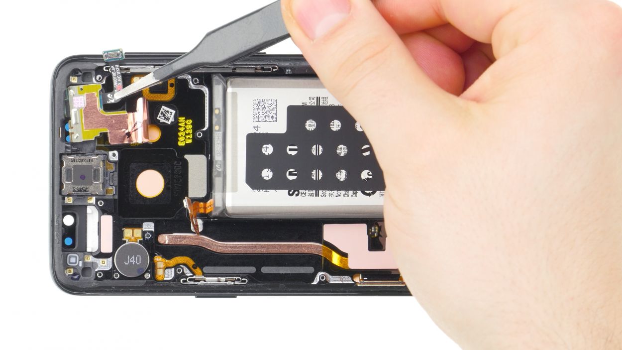
– Hey there! The sensor cable is snugly glued to the display, so grab a flat tool and gently coax it free—just be careful not to give it a rough time!
– Now, let’s delicately extract the flex cable using tweezers. You’ve got this!
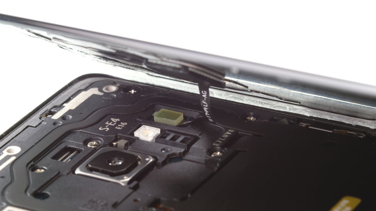
Step 12

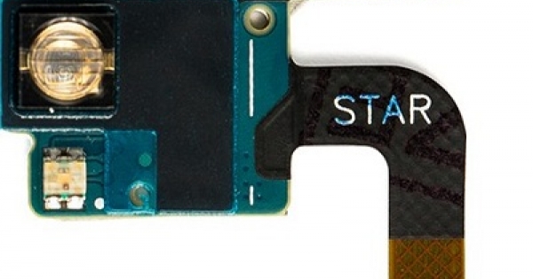
– Time to snuggle that new sensor cable into its chassis home!
– Give that sensor a gentle press with your fingertip – it’s like a tiny hug that secures it in place.
Step 13

1 × 3.4 mm Phillips
– Grab that logic board and plug in the connector at the bottom like a pro!
– Now, gently fold the logic board back into the device, taking your time.
– Remember, no squishing those cables in there!
– Bend those antennas and connectors to the side with care.
– Press the logic board down until you hear that satisfying click.
– Finally, secure the logic board with its trusty single screw.
Step 14

Antenna plug
– Round 1: Plug in, Plug in, Hooray! Position those tiny antenna plugs with your tweezers and click ’em in place. Easy peasy!
– Step two: Get your connectors in order! Attach those display and volume button connectors, and listen for that satisfying click.
– Bonus tip: If something feels off, don’t worry, buddy! Just gently remove and try again. That click you hear is your badge of honor.
Step 15
If things are feeling a bit stuck, it might be that the logic board isn’t snug in its spot. Let’s give it a little check!
– Time to pop that SIM tray back in!
Step 16
– Pop in the front camera and snugly connect its cable.
Step 17
5 × 4.0 mm Phillips
– Now, carefully place the speaker back above the USB board, gently press it down, and give it a good twist to secure it.
– Double-check that it’s nicely hooked in at the bottom.
Step 19


10 × 4.0 mm Phillips
– Now, let’s get that midframe back in place with the NFC tag. Just pop it on there!
– Give it a good press all around to make sure it’s snug as a bug.
– And don’t forget to secure all the screws again to keep everything in place!
Step 20
Fingerprint connector
– Alright, before you pop that back cover back on, don’t forget to reconnect the fingerprint sensor! It’s like giving your device a little high-five.
– Now, gently place the back cover over the device and lift it just a tad. This gives you a clear view of the connector. Keep that back glass steady and close to the device like it’s your best buddy.
– Grab a plastic tool, like a spudger, to reach for that connector and give it a little push down. If you’re feeling adventurous, you can opt for longer tools like ESD tweezers or an ESD spudger. Just take your time and keep those hands steady, you got this!
Step 21

Just a heads up, once you crack open your smartphone, its water resistance takes a little vacation. Keep that in mind while you work!
– Before you put that back cover on, take a moment to check the glue. It should be spread out nicely on the back cover. Feel free to wipe away any extra glue that might be hanging around.
– Next up, give the back cover a good press down.
– Now, let’s heat things up a bit! Warm the back cover again to help the glue stick like it means it.
– While the glue is cooling, you can give the back cover a gentle press with your fingers. It’s a great way to make sure everything settles in just right.