DIY Guide to Replace iPhone 5 Standby Volume Control Cable
Duration: 75 min.
Steps: 33 Steps
Get ready to dive into the exciting world of iPhone repair! In this guide, we’re going to tackle that pesky standby/volume control cable on your iPhone 5. You’ll want to do this if your standby button is feeling a bit lazy or lacking that satisfying click. It’s also the perfect fix if the mute button or those volume buttons have decided to take a break. Let’s roll up our sleeves and get your iPhone back in action!
Step 1

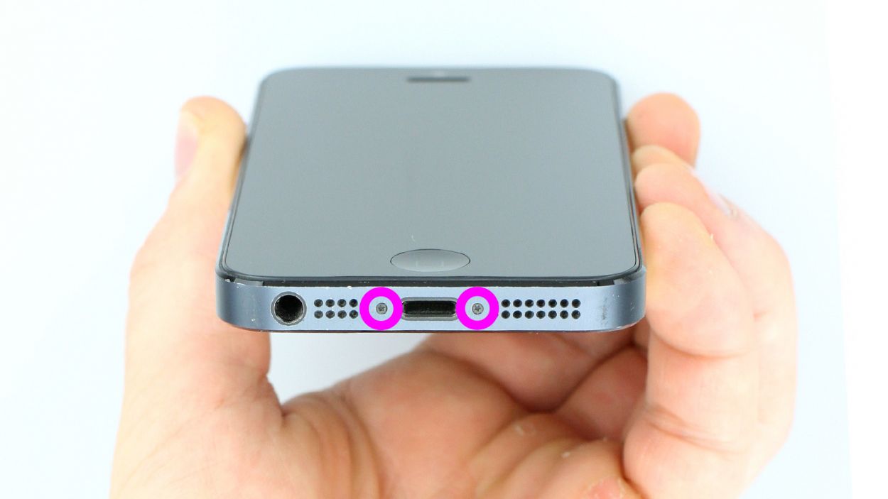
– Grab your trusty pentalobe screwdriver to get that iPhone 5 open!
– Now, let’s tackle those two pentalobe screws at the bottom of the enclosure. They’re hanging out right next to the Lightning connector, one on each side. Don’t forget to stash those screws in the same compartment of your organizer tray. You’ve got 2 x 3.6 mm pentalobe screws to keep track of!
Step 2

– Place your iPhone 5 on a soft, clean surface so it doesn’t end up with any back scratches.
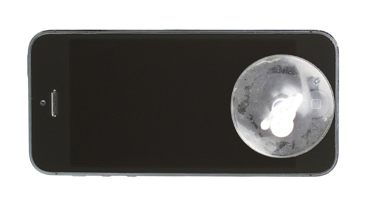
– You’ll need a suction cup and a hard plastic pick to lift the front panel. If your screen looks like a battle zone, cover the cracks with packing tape first.
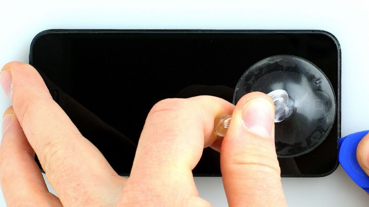
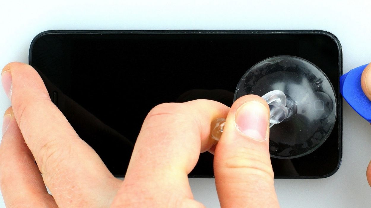
– Place the suction cup over the Home button (if it’s possible) or just next to it (check out figure 1). While using the suction cup to gently lift the screen, slip the hard plastic pick between the aluminum frame and the display frame; press down on the aluminum while you do this. Keep the pick handy to help raise the screen (see figures 2 and 3). It might take a few tries, but you’ve got this!
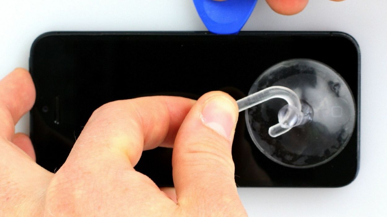
– Once the screen can lift just a tad (see figure 4), work your way around the edges ever so carefully to loosen it on both sides (see figure 5).
– When the display is finally free, you can lift it up at the Home button. Just a heads up: the display cables are still attached to the logic board (next step incoming).
Step 3

– First, grab your Phillips screwdriver and remove those three screws from the shiny silver cover (check out figure 1 for a visual!). Make sure to toss those screws into the same compartment of your organizer tray—2 x 1.2 mm Phillips screws and 1 x 1.7 mm Phillips screw (the non-magnetic one).
– Now, it’s time to disconnect the three connectors (see figure 2). Just a friendly reminder to be super careful here!
– Take your spudger and gently slide the pointed tip just below the contact, then lift it up. Watch out for those resistors soldered onto the logic board—don’t break them! In newer models, they’re protected by a black plastic film. You’ve got the LCD, touchscreen, and front camera/sensor/earpiece to handle.
Step 4
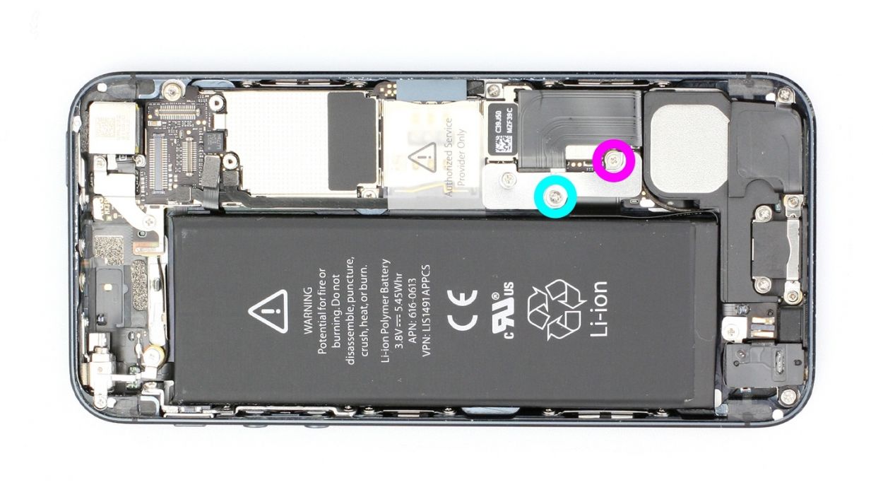
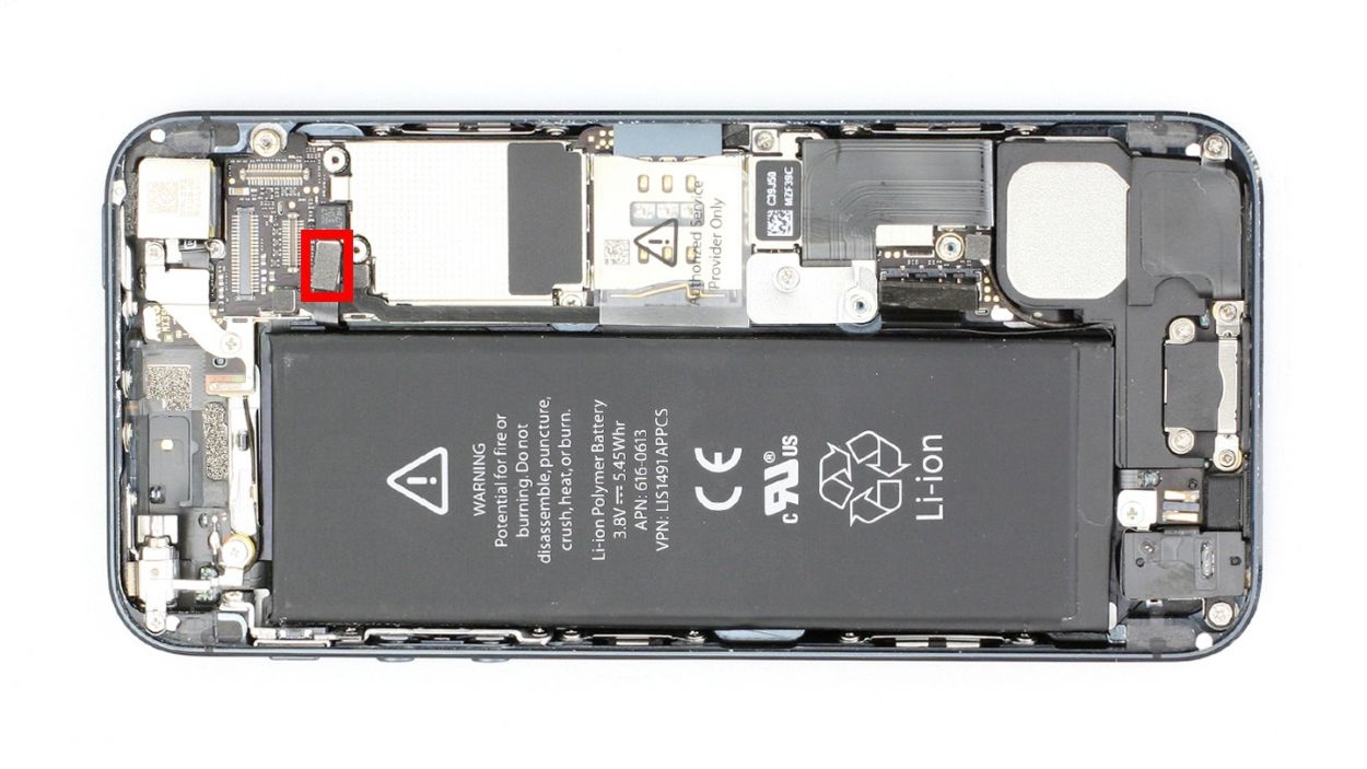
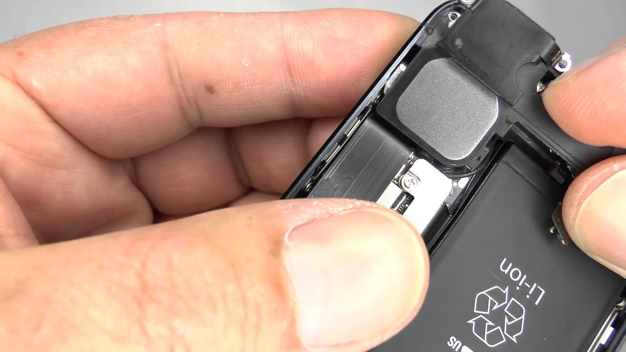
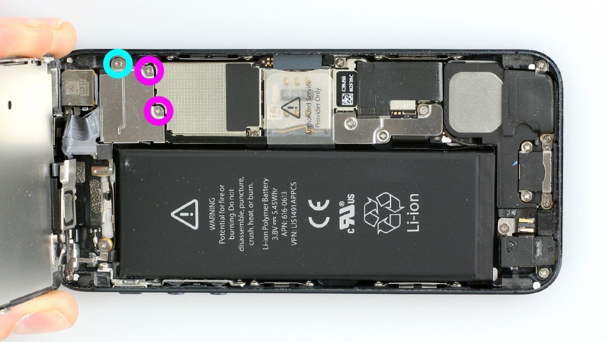
– Grab your Phillips screwdriver and get ready to tackle those Phillips screws on the battery connector (check out figure 1 for a visual!). Once you’ve done that, gently lift the cover using your trusty spudger (figure 2 is your guide). Remember to keep all those little parts cozy in the same compartment of your organizer tray. You’ll be dealing with 1 x 1.8 mm Phillips screw (funnel head) and 1 x 1.7 mm Phillips screw.
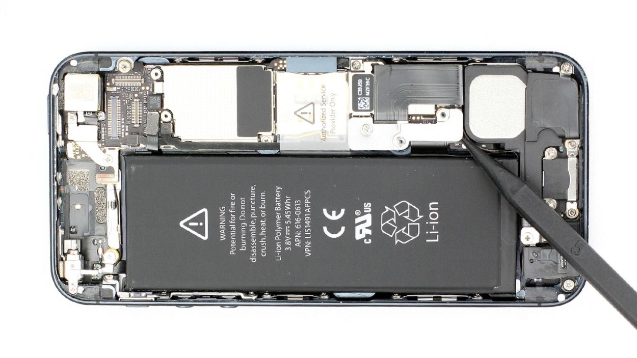
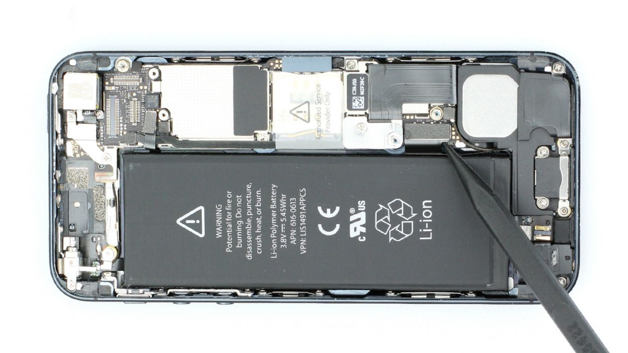
– Now, with a steady hand, carefully lift off the battery connector by sliding the pointed tip of the ESD spudger just below the connector (figure 3 will show you how). If you don’t have a spudger handy, your fingernail can do the trick too!
– Time to test out that new cable set! First, connect the new cable set temporarily. Then, reattach the display. After that, connect the battery. Fire up your iPhone and check if the volume up/down buttons, mute button, and standby button are back in action. You got this!
– Just a reminder: temporarily connect that new cable set.
– Reconnect the display.
– Then, connect the battery.
– Finally, start your iPhone and see if the volume up/down buttons, mute button, and standby button are working like a charm!
Step 5

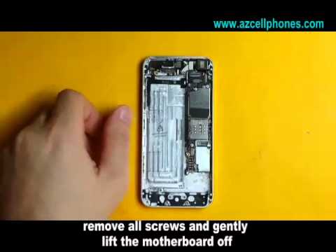
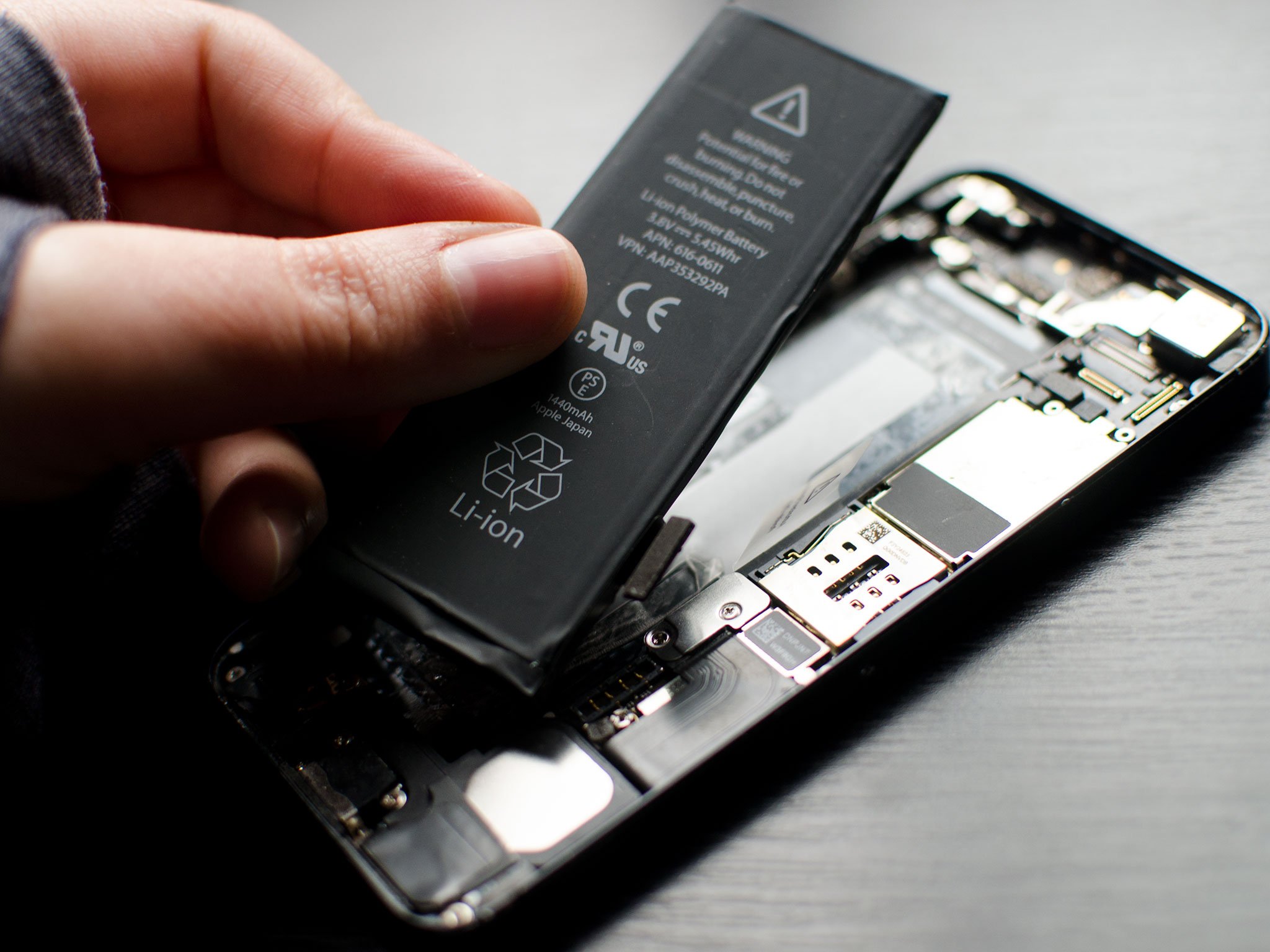
Heads up! That logic board is super sensitive, so be gentle. You can also try lifting the battery from the other side – whatever works best for you!
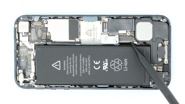
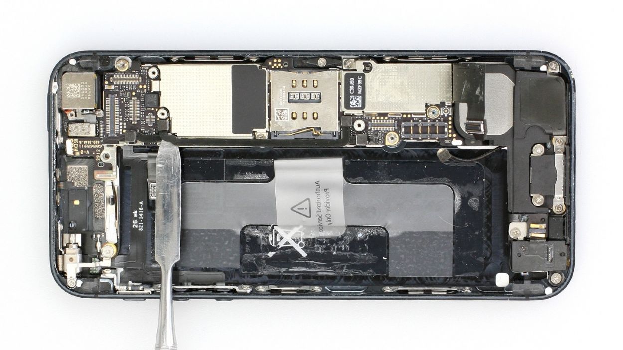
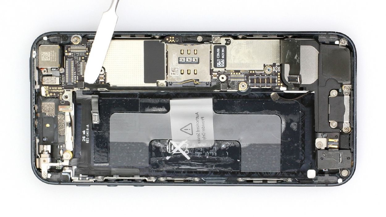
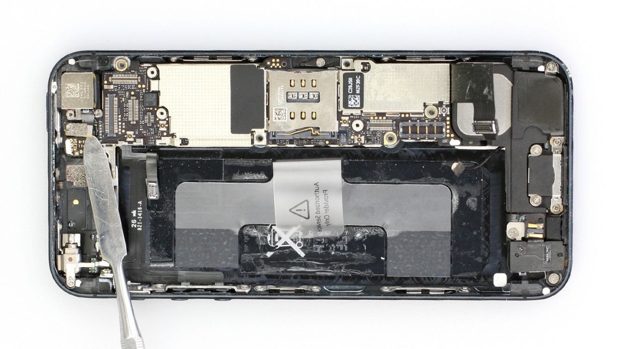
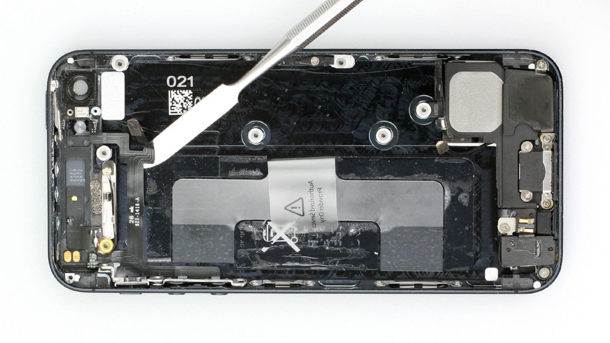
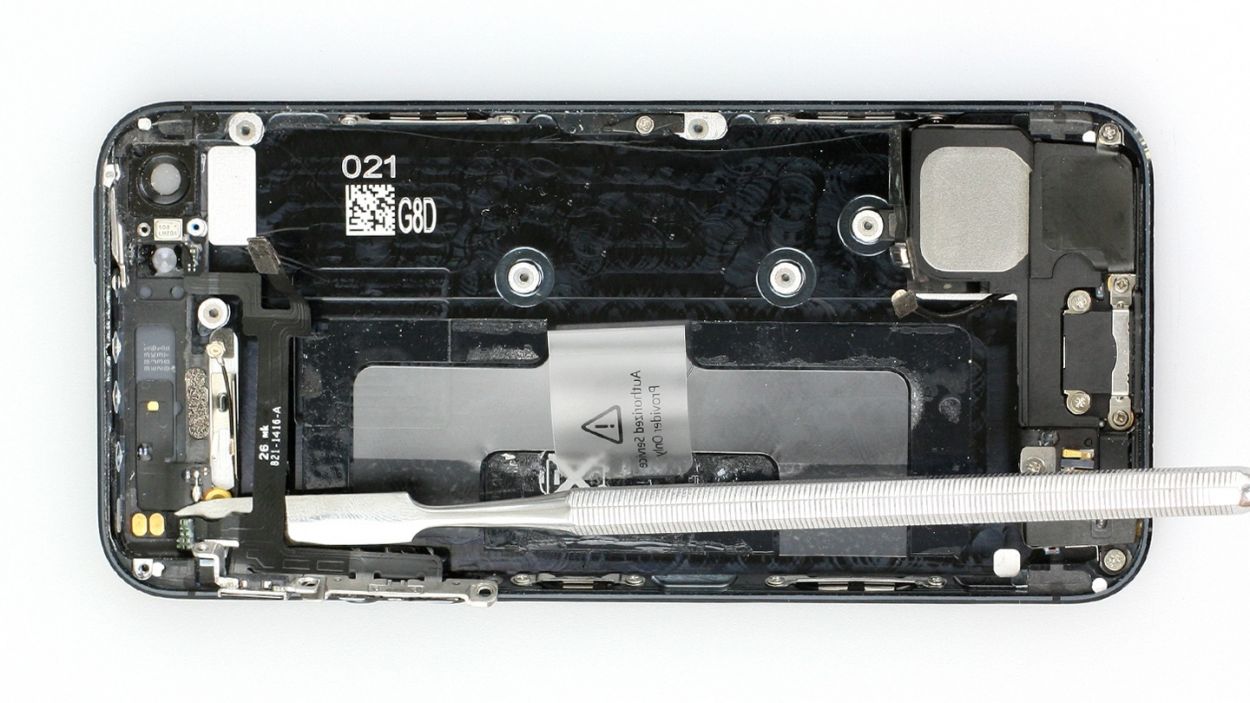
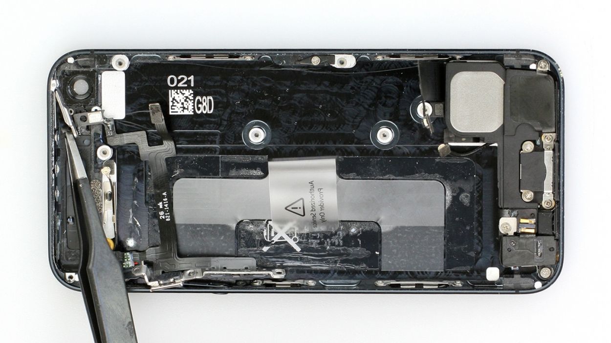
– Now remove the battery. It’s sometimes glued firmly in place. Insert the flat end of the spudger into the space between the battery and the logic board, and carefully lift the battery.The logic board is very sensitive. You can also lift the battery from the other side.If the battery’s really stuck on, use other leverage points to the right and left of the original spot to pry it off. If you still can’t detach the battery, you can use a heat gun to slightly warm the glue from the outside and soften it.
Step 6
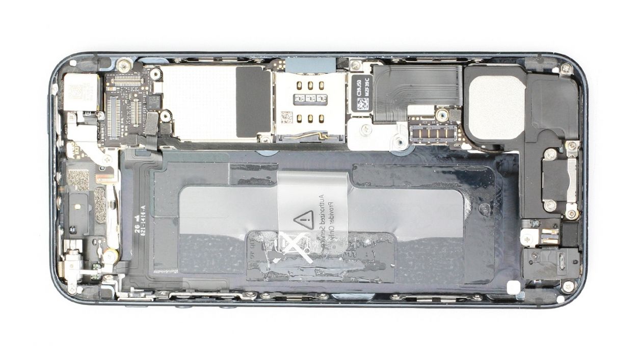
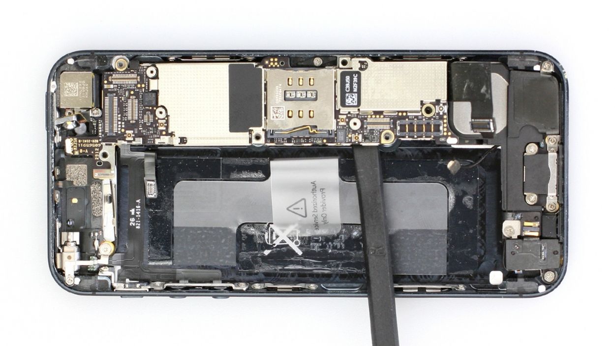
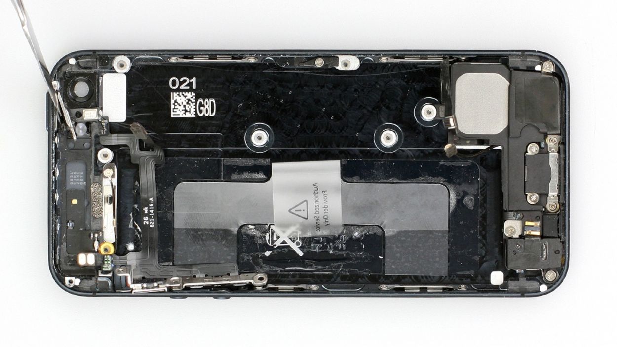
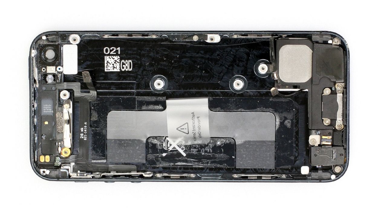
– Fold the plastic tab with the warning over and press it down snugly onto the adhesive strip. This little move will keep it out of your way while you work your magic on the repair!
Step 7

– Ready to ditch that SIM card tray? Grab your SIM tool (or a paperclip—you’re resourceful!), and gently nudge it into the tiny hole. Pop! Out it comes!
Step 8
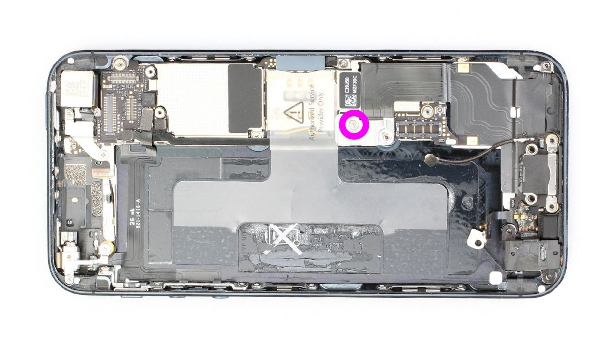
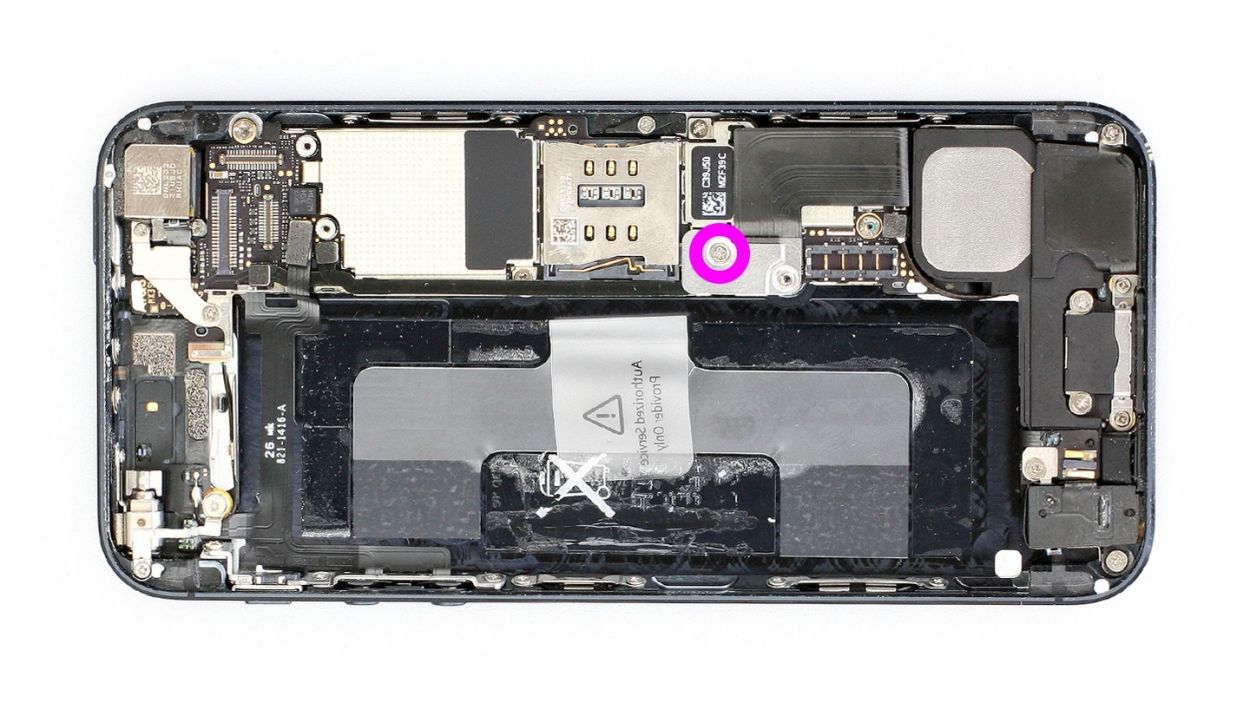
– First, take your Phillips screwdriver and remove that shiny silver cover right below the screw (check out figure 1 for a visual!). Don’t forget to toss those screws into the same compartment of your organizer tray—1 x 1.2 mm Phillips screw to keep track of!
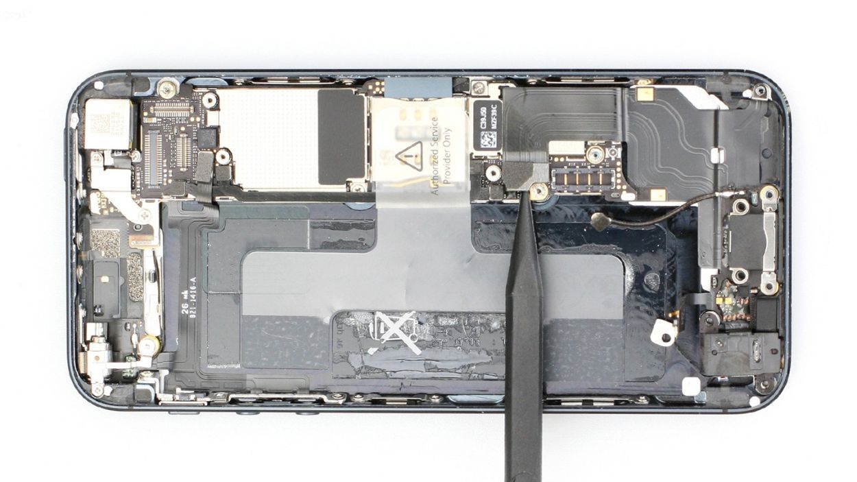
– Next up, let’s disconnect the Lightning connector’s ribbon cable (see figure 2). Gently slide the pointed tip of your spudger just below the contact and lift it up. Once you’ve done that, carefully fold the cable over. Easy peasy!
Step 9
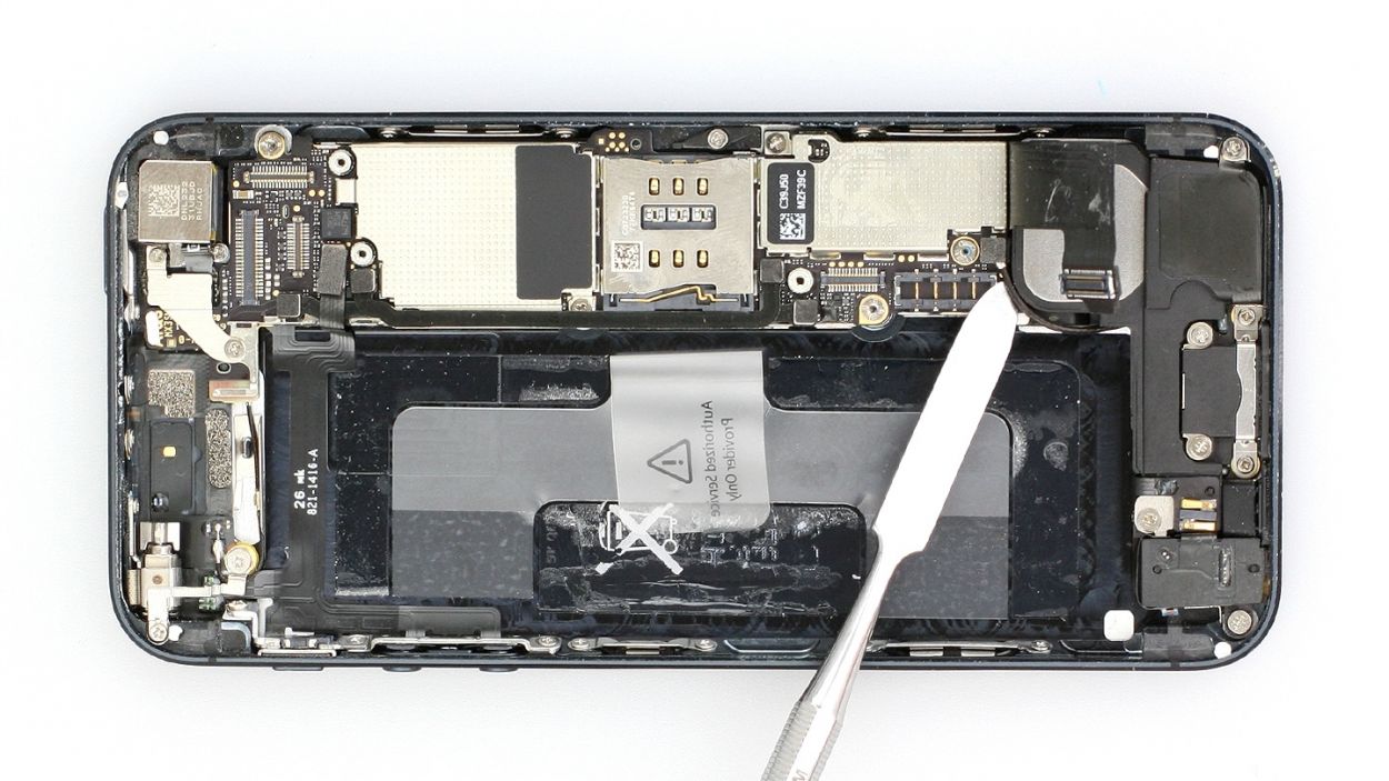
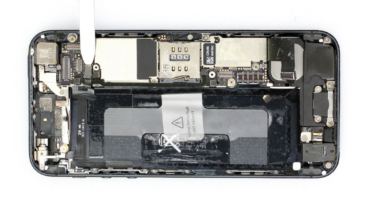
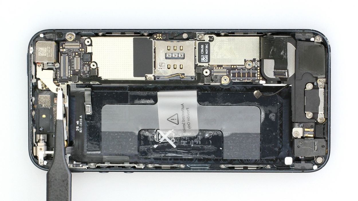
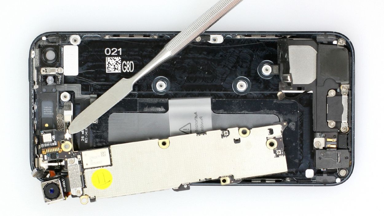
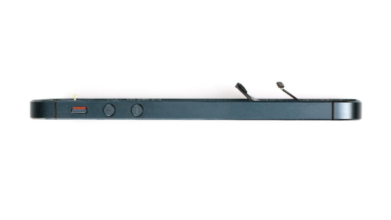
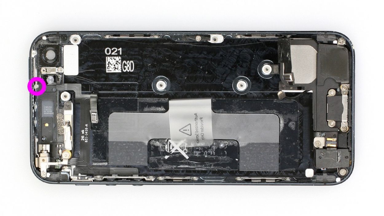
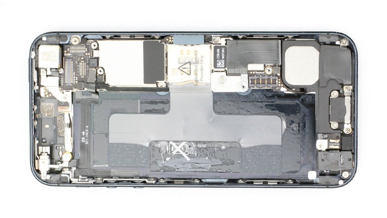
– Gently lift the antenna connector using your trusty laboratory spatula (check out figure 1 for a visual!).
– Next, lift the standby/volume cable set connector to remove it (see figure 2). Now, carefully slide the pointed tip of your spudger or spatula just below the contact and give it a little lift. Remember, those resistors soldered onto the logic board are delicate—let’s not break any of them!
Step 10
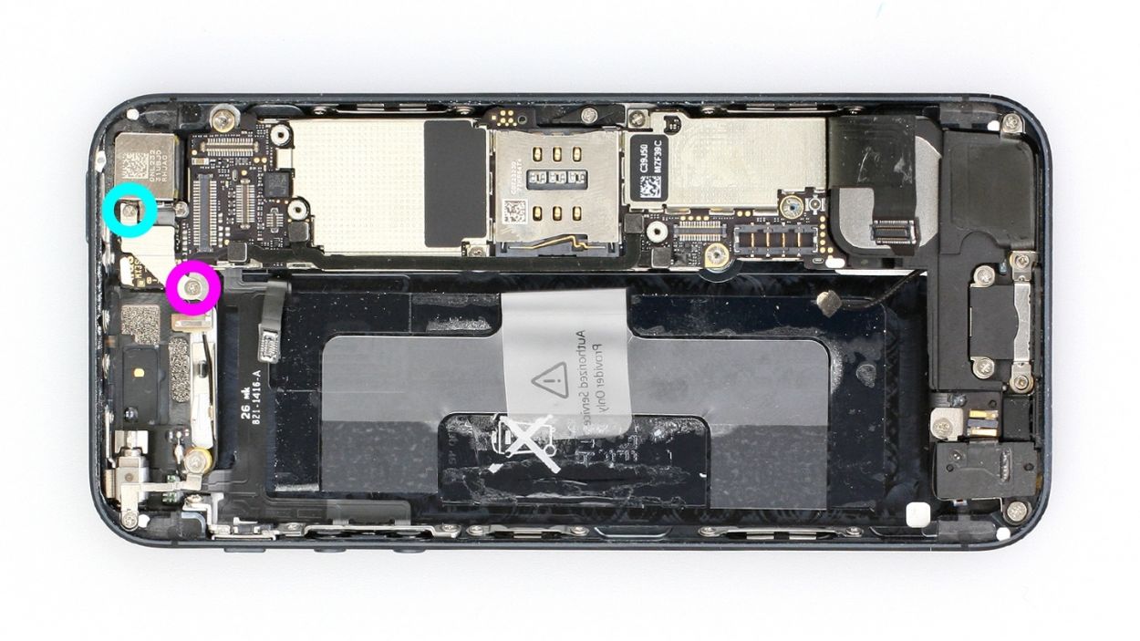
– Let’s kick things off by unscrewing those two Phillips screws and taking off the bracket beneath them. Keep an eye out for another sneaky connection lurking underneath! Be sure to pop those parts into the same cozy compartment of your organizer tray. You’re looking at 1 x 2.3 mm Phillips screw and 1 x 1.5 mm Phillips screw.
Step 11

– Time to take care of those two Phillips screws holding the antenna to the frame! Just whip out your Phillips screwdriver and unscrew them like a pro. You’re looking at 2 x 1.3 mm Phillips screws here, so keep them cozy in your organizer tray!
Step 12
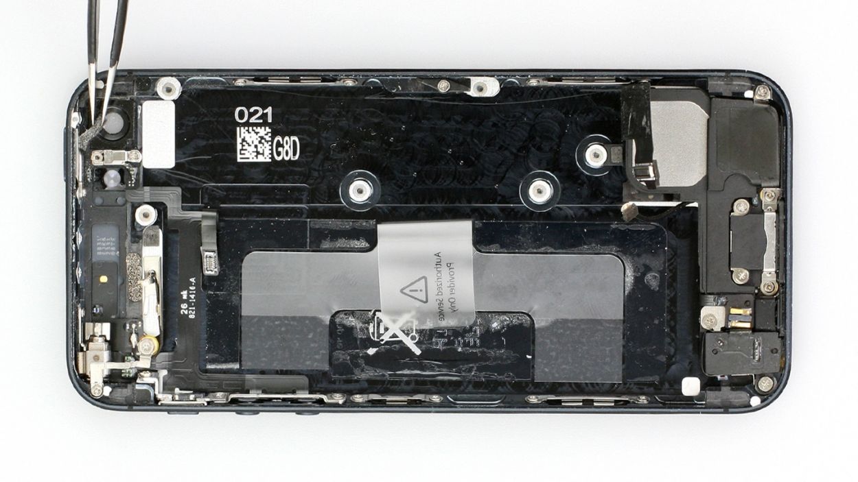
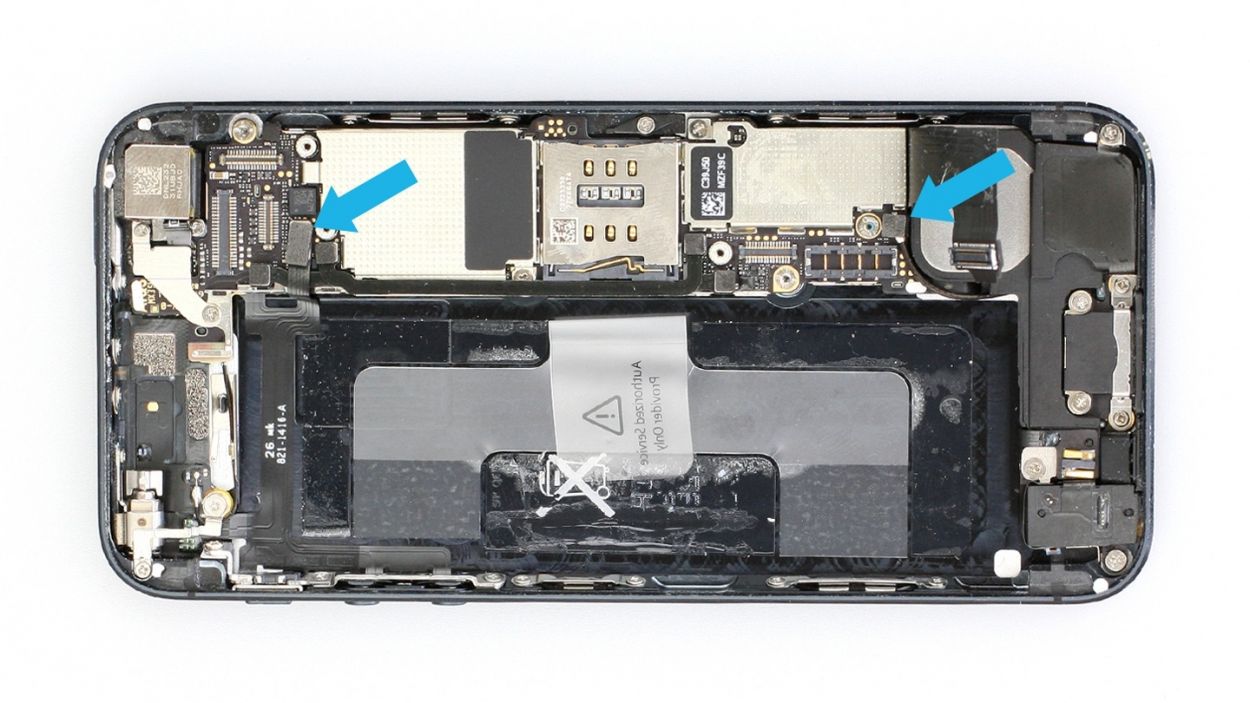
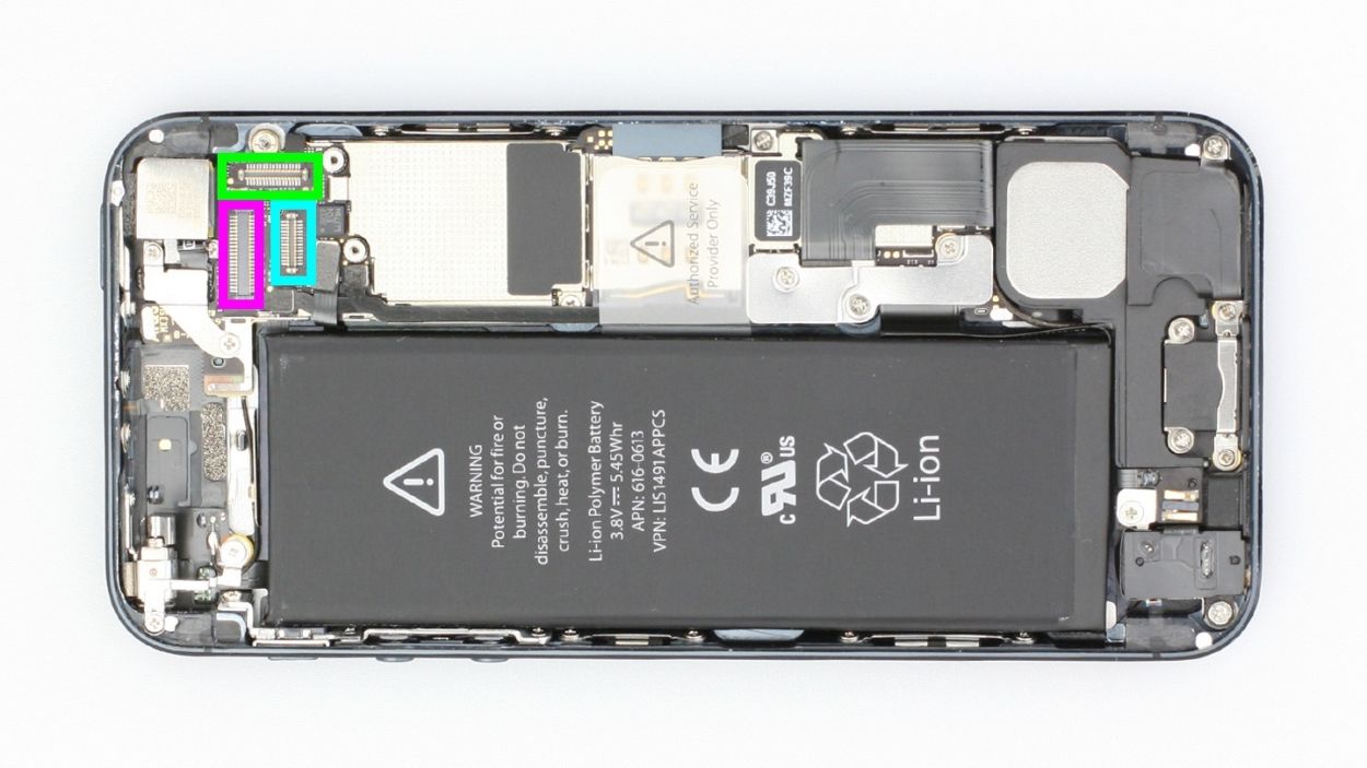
– Time to tackle those two connection cables (check out figures 1 and 2). Grab your spudger or spatula and gently slide the pointed tip underneath the contact, then give it a little lift. Just a friendly reminder: be careful not to break any of those delicate resistors soldered onto the logic board!
Step 13

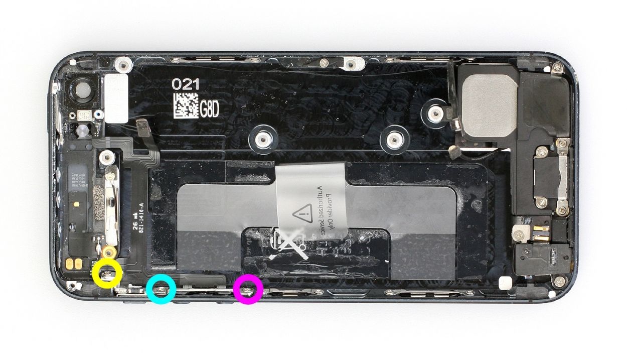
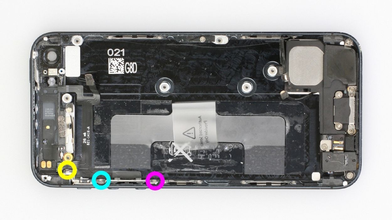
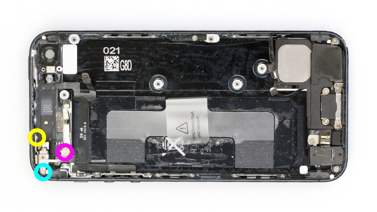
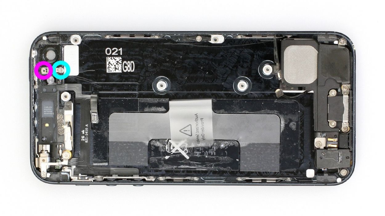
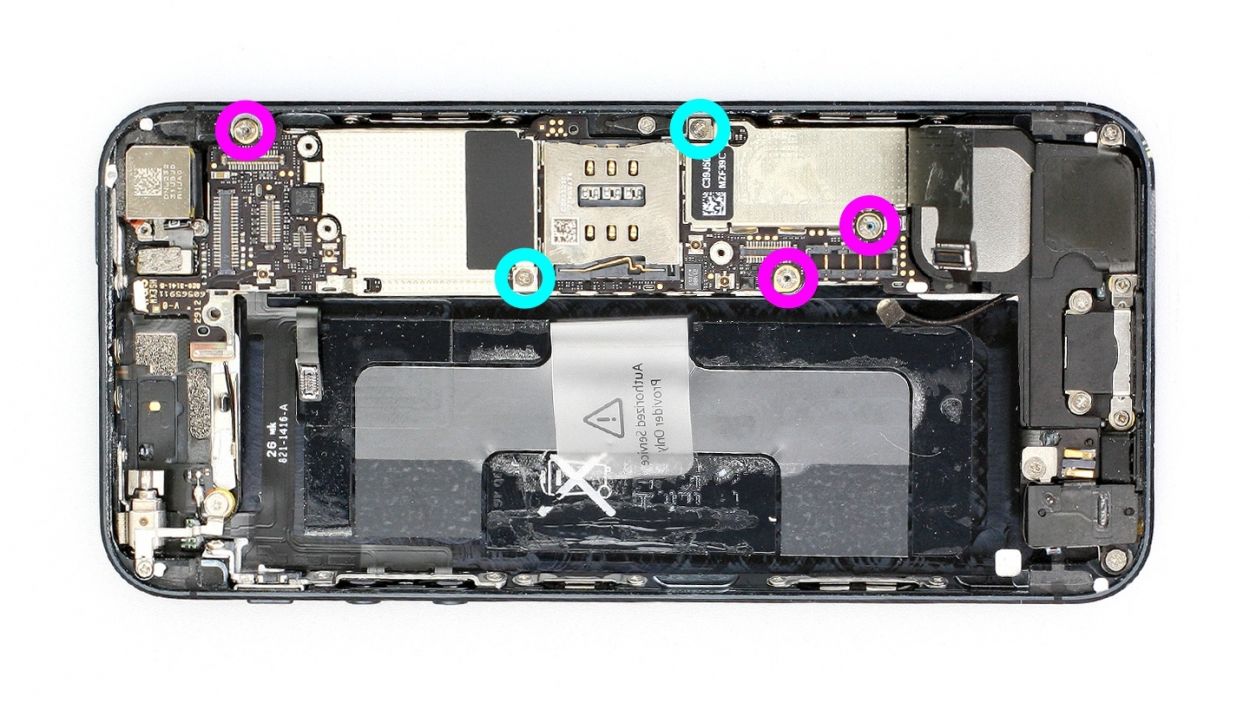
– Now unscrew all five screws that hold the logic board in place (see figure 1).
– Three of the screws have an internal thread. The one next to the rear camera isn’t magnetic. You can remove this screw with a flathead screwdriver or the spatula. Put the screws in the same compartment of your organizer tray.3 x 2.7 mm Phillips/flathead screws2 x 2.3 mm Phillips screws
– Lift the camera flash using the laboratory spatula (see figure 2).
Step 14

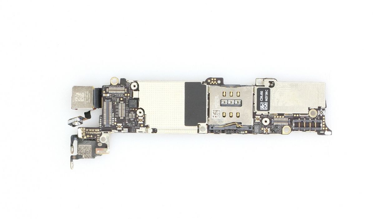
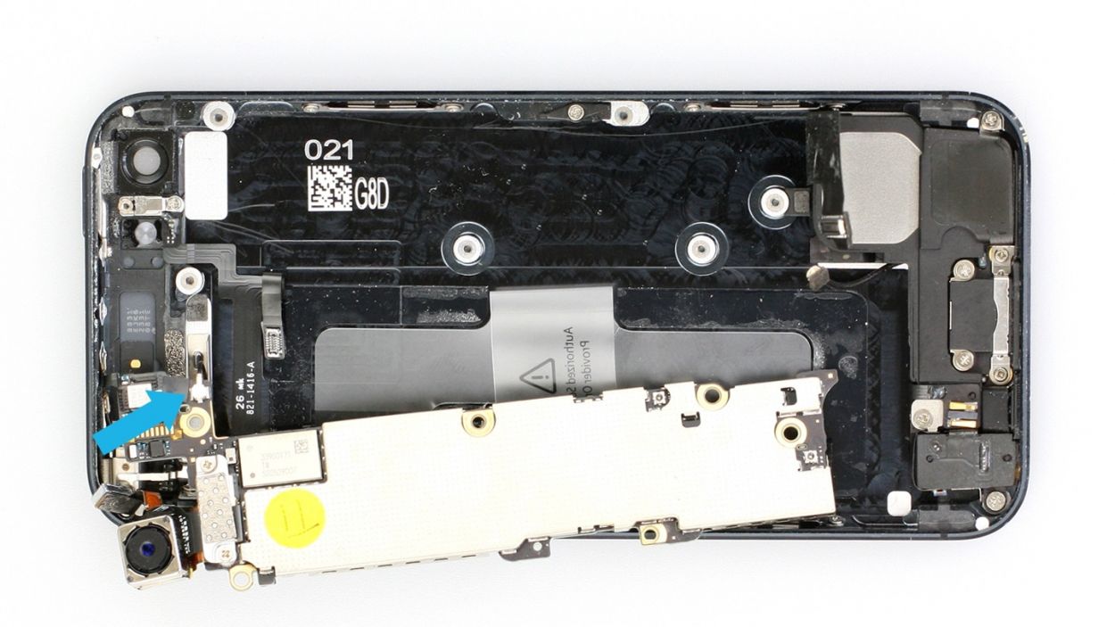
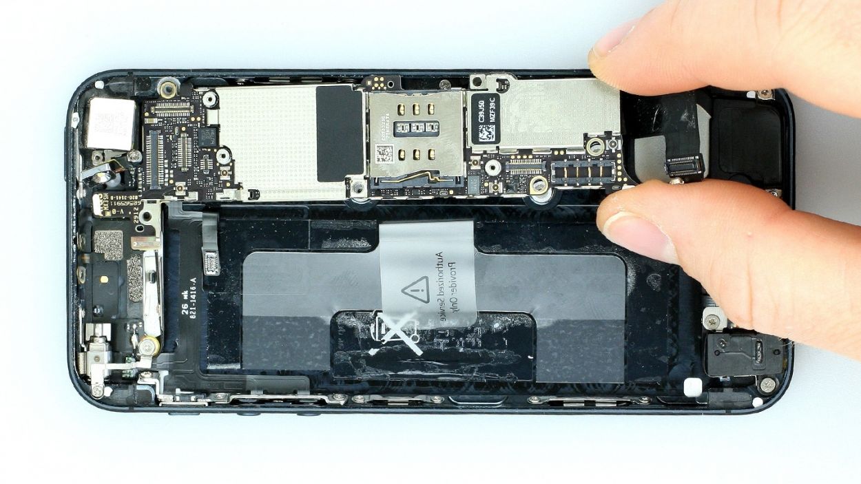
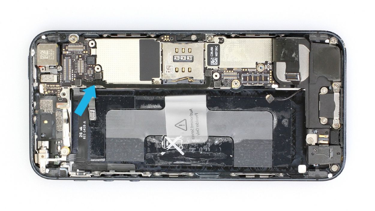
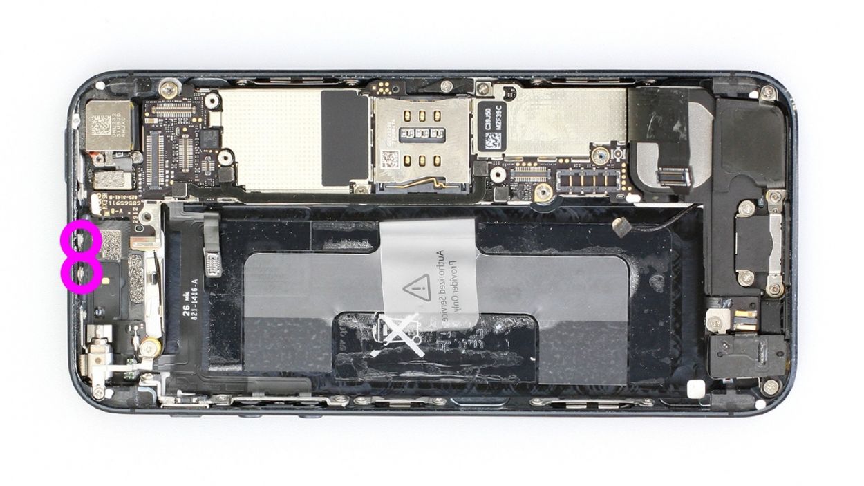
– Gently lift the logic board using your spudger (check out figure 1) and give it a little twist around the longitudinal axis by the plastic tab (see figures 2 and 3).
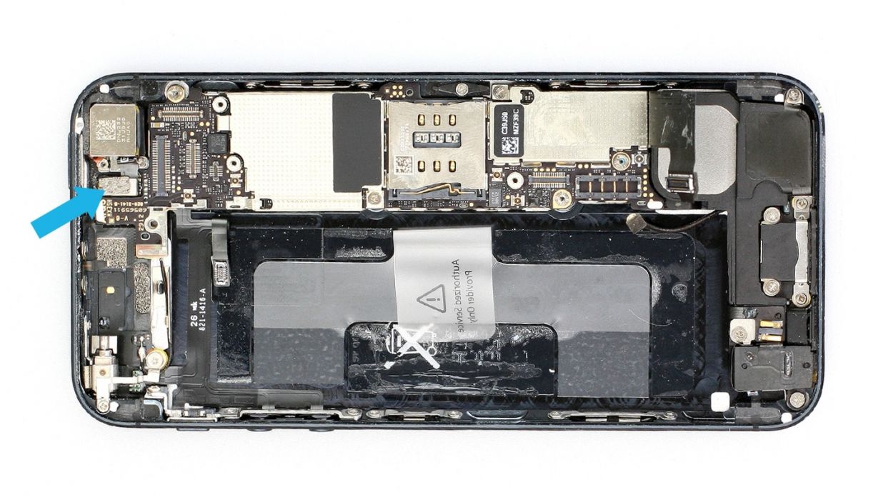
– On the flip side, carefully disconnect the antenna connector by gently pulling it off the plug head with your spudger (see figure 3).
– Now, with a steady hand, carefully take out the logic board.
Step 15

– First, let’s peel off that foam sticker (check out figure 1 for a visual!).
– Next up, grab your Phillips screwdriver and remove the Phillips screw (see figure 2). Make sure to keep the screw and foam sticker cozy in the same compartment of your organizer tray. You’re dealing with 1 x 1.9 mm Phillips screw here!
Step 16

– Alright, it’s time to tackle those screws and the metal bracket! Grab your trusty laboratory spatula or a flathead screwdriver to help you out with that sneaky screw that has an internal thread. You’re looking at 1 x 2.9 mm Phillips/flathead screw and 1 x 1.6 mm Phillips screw. Let’s get this done!
Step 17

– Let’s get those three screws out of the way! It’s a 1.8 mm, a 2.4 mm, and a 1.5 mm Phillips head – all holding the vibration motor and its frame. Piece of cake!
– Now, gently remove the vibration motor. You’re doing great!
Step 18
– Time to tackle those three Phillips screws holding the volume and mute button bracket in place! Just a heads up, this bracket is glued to the cable set, so give it a gentle nudge as you work. You’ve got this!
Step 19

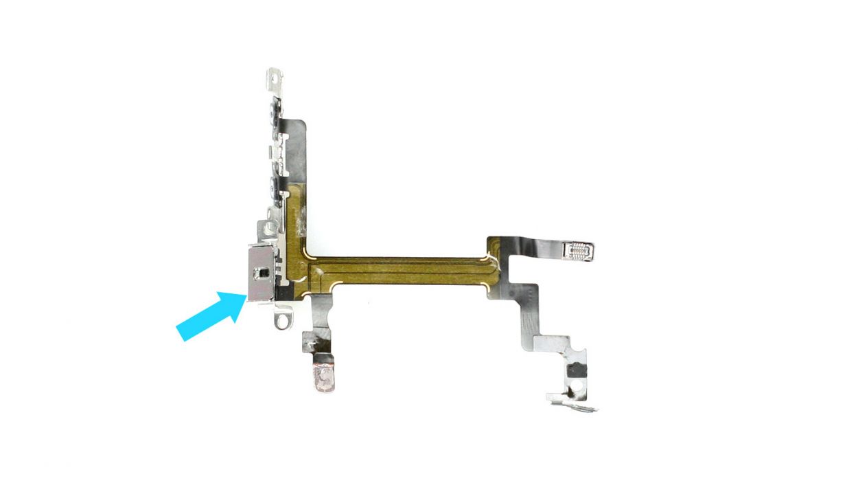
– The cable set is still lightly glued in place.Carefully detach it using the laboratory spatula (see figures 1 and 2).
– The standby button is glued to the metal rocker switch (see figure 3). Now detach the cable set from the rocker switch.It’s better if you don’t remove the rocker switch because putting it back in is pretty tough.
– Once the cable set is detached from the rocker switch, you can take it out with tweezers (see figure 4) or your fingers.
Step 20
– Take the following parts from the old cable set and add them to the new one (see figure 1):Metal rail for the volume controllerVibration switch socketSoft sticker for the connector
– Metal rail for the volume controller
– Vibration switch socket
– Soft sticker for the connector
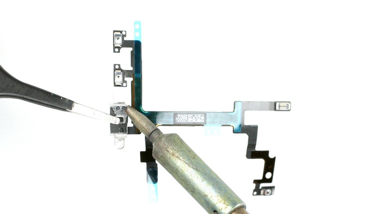
– You should solder the new cable set to the socket of the vibration switch. If you just glue it, the switch could come off of the socket. Take off the silver cover and remove the old plastic residue (see figure 2).
– You have to put the three plastic rods through the openings in the socket.Afterwards, you have to solder them as shown in figure 3 to form a little plate you can use to attach the socket firmly to the cable set.
Step 21
– Securely attach the standby button back onto the metal rocker switch (check out figure 1). This part can be a bit of a puzzle. If you’re having trouble, feel free to remove the rocker switch and then stick the standby button onto it instead.
– Reconnect the vibration switch and volume controller to their original spots (see figure 2).
– When you’re placing the vibration rocker switch, ensure that the vibration switch is facing downward (you’ll spot the orange stripe along the frame). This little detail makes it easier to connect the button to the rocker switch correctly (see figure 3).
– Next, screw in the volume and mute button bracket (see figure 4). You’ll need 1 x 1.7 mm Phillips screw, 1 x 1.8 mm Phillips screw, and 1 x 1.9 mm Phillips screw.
Step 22
– Fasten the three Phillips screws that hold the vibration motor and its support frame in place.1 x 1.8 mm Phillips screw1 x 2.4 mm Phillips screw1 x 1.5 mm Phillips screw
Step 23

– Let’s get that metal bracket on there along with the screws (check out figure 1 for a visual!). You’ll need 1 x 2.9 mm Phillips/flathead screw and 1 x 1.6 mm Phillips screw.
– Next, secure the Phillips screw on the standby switch (see figure 2). Just a heads up: the rocker frame for the standby button should be facing upward while you do this. You’ll need 1 x 1.9 mm Phillips screw.
– Finally, don’t forget to stick on that foam sticker (see figure 3)!
Step 24
– Reconnect the WLAN antenna connector to the logic board (check out figure 1) and gently place the logic board back in its original spot (see figure 2). Use figure 4 to make sure your logic board is sitting pretty in the right position.
– Next, pop in the camera flash (see figure 3).
– Now, let’s get those five screws back in to secure the logic board (see figure 4). You’ll need 3 x 2.7 mm Phillips/flathead screws and 2 x 2.3 mm Phillips screws. You’re almost there!
Step 25
– Reconnect those two connection cables like you mean it! Just double-check that the connectors fit snugly in their little homes.
Step 26
– Let’s get those two Phillips screws that hold the antenna to the frame all snug and secure! You’re working with 2 x 1.3 mm Phillips screws here, so don’t let them wander off. Keep them cozy in your organizer tray!
Step 27

– Alright, let’s get that bracket installed and secure it with those two Phillips screws! You’ll need 1 x 2.3 mm Phillips screw and 1 x 1.5 mm Phillips screw. You’re doing great!
Step 28
– Reconnect the antenna connector and the standby/volume cable set connector, just like in figure 1.
– Next, it’s time to connect the ribbon cable. Place the cover back on, and secure it with a screw (check out figure 2 for a guide). You’ll need 1 x 1.2 mm Phillips screw for this step!
Step 29
– If you pulled out the plastic tab with the warning, now’s the time to either pop it back in or just remove it with ease. Easy peasy!
Step 30

– Alright, let’s get that battery back into your iPhone! Make sure to place it as close to the logic board as you can—like a cozy hug.
– Now, give that battery connector a little click to secure it in place. You’re doing great!
– Finally, pop the cover back on and screw it in tight. You’ll need 1 x 1.8 mm Phillips screw (funnel head) and 1 x 1.7 mm Phillips screw to finish the job!
Step 31

– Alright, champ, let’s reconnect those connectors (see figure 1)! Sometimes the LCD connector gets a little shy when you’re connecting the touchscreen one. Don’t worry, we’ve got you covered. Remember to connect the LCD, touchscreen, and front camera/sensor/earpiece.
– Next up, reattach the battery connector and pop that cover plate back on. Easy peasy!
– Now, fire up your iPhone! Once those connectors are snug, check if your LCD, touchscreen, proximity sensor, front camera, and earpiece are all working their magic.
– Time to put on the finishing touches! Attach the cover and screw it in (see figure 2). We’re talking 2 x 1.2 mm Phillips screws and 1 x 1.7 mm Phillips screw (the non-magnetic one).
– Gently fold down the screen, making sure that the edge with the cables clicks into place. Then, give it a nice, firm press towards the Home button to make sure it’s all snug in the frame (See figure 3). You’re a rockstar!
Step 32
– Now, let’s get those two pentalobe screws at the bottom of the enclosure all snug and secure! They’re 2 x 3.6 mm pentalobe screws, just waiting for you to give them a twist. You’ve got this!
Step 33

Heads up! When you pop out that battery, your iPhone takes a little trip back to 1:00 a.m. on 1/1/1970. Don’t forget to set the right time, or you might find yourself in a pickle when trying to connect to the cellular network!
– Let’s get this party started! Sync your iPhone with iTunes or hook up to Wi-Fi and chill until the time is right.
– Time to give your SIM card a little vacation. Pop out the SIM tray, give the SIM card a quick hello, and then pop it back in.
– Activate airplane mode, then turn it off. It’s like a little reset button for your iPhone’s time zone!