DIY Tutorial: iBook G4 14″ Optical Drive Replacement Guide – How to Replace Optical Drive in iBook G4 14 Inch
Duration: 45 minutes
Steps: 42 Steps
Heads up, awesome tech adventurer! Before diving into this repair escapade, make sure you’ve got your data backed up safely. If things start feeling a bit too wild, don’t fret—consider hitting up the experts and schedule a repair. Got it? Let’s get to it!
Ready to give your new optical drive a boost? Let’s move the hardware from your old one to the new! If you need help, you can always schedule a repair.


Step 2

– Give those keyboard release tabs (the ones in yellow) a gentle tug towards you and lift the keyboard up until it pops right out. Easy peasy!
– If the keyboard is feeling a bit stubborn, grab a small flathead screwdriver and give that keyboard locking screw (the one in orange) a twist—180 degrees in either direction should do the trick. Then, give it another go!
– Now, flip the keyboard over, away from the screen, and let it rest face-down on the trackpad area. You’re doing great!
Step 3

Don’t worry if the screws won’t come all the way out. These little guys are on a mission, staying put to keep the RAM shield company. They’re not going anywhere!
– Give those four silver Phillips screws a gentle twist to set the RAM shield free. If you need help, you can always schedule a repair.
Step 4

When you remove the RAM shield, those four captive screws will come right along for the ride!
– Go ahead and take off the RAM shield from your computer. You’ve got this!
Step 5

– Gently lift the keyboard cable up from the logic board, making sure to hold the cable as close to the connector as you can.
– When putting your iBook back together, be sure to reconnect the keyboard cable before putting the RAM shield back in place.
Step 6

– Alright, close up that display and flip your computer over like a well-seasoned pancake.
– Grab your trusty T8 Torx screwdriver and remove those three hex screws. You got this!
– Remember, the shorter screw is hanging out in the center, so don’t forget to snag it.
Step 7

– Grab a spudger or a small flathead screwdriver and say goodbye to those three rubber feet on the lower case!
Tools Used

Step 8

Sneaky, sneaky! There’s a screw hiding under each bumper—three of them, to be exact.
– Time to get those screws out! Grab your trusty Phillips screwdriver and remove the three screws that just made their grand entrance.
Step 9

– Grab a spudger or a small flathead screwdriver to pop off those three metal rings that were home to the rubber bumpers. If you need help, you can always schedule a repair.
Tools Used
Step 10

– Time to show those screws who’s boss! Remove the two Phillips screws flanking the battery contacts.
Step 11

Take a deep breath and stay cool. We know the journey ahead might be a bit tricky, but rest assured, that lower case will come off!
– Gently press the slender edges of the lower case around the battery compartment, flexing them past the tabs, and then lift upwards to release that corner of the lower case. Remember, you’re doing great!
Step 12

– Look for the little slot on the wall of the battery compartment that keeps the lower case snug and secure. Grab a small flathead screwdriver and gently pry up the lower rim of that slot. Once you’ve got it loose, give a little tug on the lower case to release it from the tabs holding it in place. Easy peasy!
Step 13

– Grab your trusty spudger and groove it along the joint between the lower case and upper case at the front of your computer. Wiggle and nudge it until you pop those sneaky tabs loose, unlocking the lower case. Give it a gentle lift while continuing to rock that spudger until you hear three satisfying clicks. Need a hand? Don’t hesitate to schedule a repair!
Tools Used
Step 14

– Alright, onward we go! Keep that trusty spudger moving around the front and right corner. You’ll run into two little tabs on the port side: one near the front corner, and the other chilling by the sound-out port. Keep your groove steady, and remember, if things get tricky, you can always schedule a repair!
Tools Used
Step 15

– Before you can pop off that lower case, you’ve got to tackle three sneaky tabs hiding above the optical drive. Grab your trusty spudger and slide it gently into the lower case right over the optical drive. Now, glide it towards the back of the computer until you hear three satisfying clicks—those are the tabs giving up!
Tools Used
Step 16

You’ve successfully freed the front and sides of the lower case. Nice job!
– Flip your computer around so the back is looking right at you. Now, gently lift the lower case towards you until those pesky back tabs give way and pop free.
– A little wiggling action up and down might just do the trick!
Step 17

– Gently pop out those little greasy springs with their snazzy white plastic caps from both sides of the battery contacts. You’re doing great!
Step 18

– Time to get to work! Unscrew those 10 screws from the bottom shield and let’s see what’s inside!
Step 19

– Gently lift off the bottom shield.
Step 20

– Unscrew that lone Phillips screw holding the DC-In board in place. You’ve got this!
Step 21

To get started, gently peel off the tape holding the DC-In board cable in place.
– Carefully tilt the DC-In board out of its snug little home.

Step 23

Gently wiggle that connector along the logic board’s surface while giving it a little tug. It might just pop right off!
– Go ahead and unplug that DC-In cable from the logic board. If you need help, you can always schedule a repair.
Step 24

– Time to get your screwdriver ready! Let’s tackle those 11 screws hanging out at the bottom of your computer. Remove them one by one and get ready for the next step!
Step 25

To keep your computer safe and sound, we suggest resting it on a soft cloth from this moment forward. This little step helps protect that precious logic board from any unexpected bumps.
– Flip your computer over and pop it open.
– Unscrew those 3 Phillips screws hanging out near the keyboard area.
– Remember, the short screw is the VIP in the lower left corner, marked with a blue ‘L’ in the photo, which is actually on the right side.
Step 26

Hey there! When you’re unplugging those cables in the next steps, remember to treat ’em gently. Don’t yank! Use a spudger to pop the connector straight from its socket.
Take your time while lifting the upper case; the tabs are still holding on to the metal frame. If you need help, you can always schedule a repair.
– Gently lift the upper case and use your trusty spudger or finger to pop the trackpad connector loose—it’s hiding just under the white plastic tab. Need a hand? You can always schedule a repair.
Tools Used
Step 27

Be gentle with those motherboard sockets on your iBooks! They’re a bit fragile and can break easily, so take your time when unplugging connectors. You’ve got this!
– Gently lift the upper case just enough to unplug the blue and white power cable from the logic board. Use your fingernails to carefully wiggle the connector free from its socket.
– Next up, with the same gentle touch, disconnect the multicolored speaker cable from the logic board. You’ve got this!
Step 28

– Time to be the hero! Remove these 16 screws carefully:
– While putting it back together, make sure to pass the screw near the left hinge through the loop in the display data cable. It’ll snugly secure the cable to the upper case, like a friendly hug!
Step 29

– Gently lift the top shield from the right side, but keep an eye on that upper left corner—it might get a little cozy with the metal framework.

Step 31

– Unscrew these 3 little buddies:
Step 32

Here’s a cool snapshot of the ribbon clamp connector you’ll be unplugging next. Take your time and you’ll do great!
– 1) Grab the locking bar with your fingernails and give it a gentle lift—just a smidge, like 1/16″ or 2 mm. You’ve got this!
– 2) Once the locking bar is free, slide that cable right out of the connector. Nice and easy! If you need help, you can always schedule a repair.
Step 33

– Go ahead and pop that optical drive ribbon clamp open, just like we talked about earlier. Now, gently slide the optical drive ribbon out of its cozy connector. You’re doing great!
Step 34

– Gently lift the optical drive out of the metal frame, giving it a little wiggle if needed!
Step 35

– Peel away the tape that’s holding the reed switch cable to the optical drive. You’ve got this!
Step 36

– Gently detach the reed switch board from the optical drive and place it to the side for now.
Step 37

– Get ready to rock and roll by removing those two Phillips screws that are holding the metal bracket and cable in place on the back of the optical drive.
Step 38

– Gently lift the cable from the top of the optical drive, making sure to peel off any tape that might be holding it down, and then unplug its connector from the optical drive. You’ve got this!
Step 39

– Let’s get that bezel out of the way! First up, grab your trusty Phillips screwdriver and remove the single screw that’s holding the bezel to the front of the optical drive.
– Heads up! This screw is a bit longer than those other two sneaky ones securing the bracket and cable at the back. Don’t mix them up!

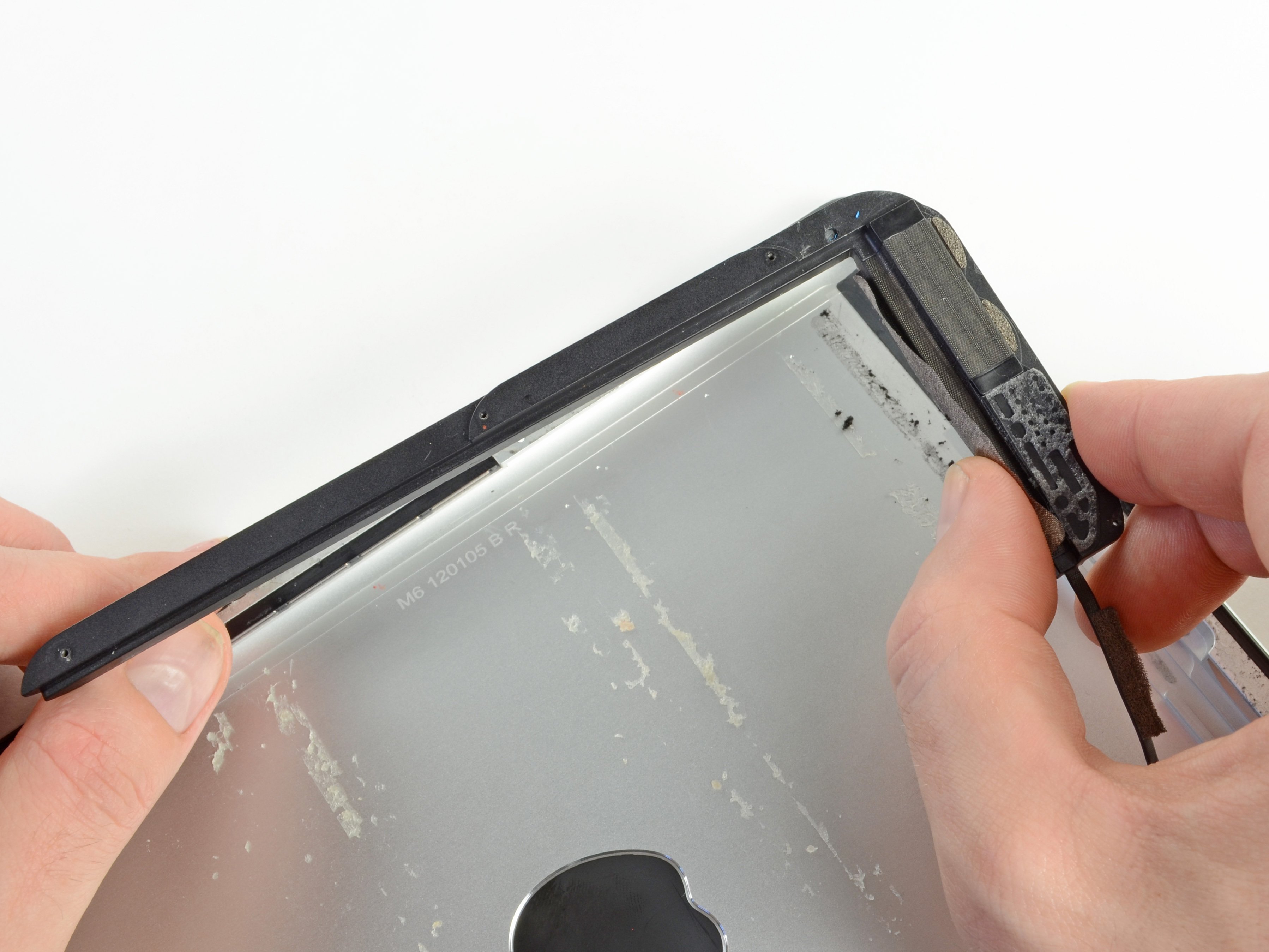
Step 41

– Grab that optical drive and set it on its side. Give that last little tab a press to pop the bezel free from the drive, and you’re one step closer to success!
Step 42

These screws are just a bit threaded, almost as if they couldn’t make up their mind!
Got a CD or some mysterious object stuck in your optical drive? No worries, we’ve got an optical drive repair guide to help you out. If you need help, you can always schedule a repair.
– Flip that drive over and unscrew those two Phillips screws holding the bracket on the side. You’ve got this!