Xbox Series X SSD Replacement
Duration: 45 minutes
Steps: 43 Steps
Make sure to power down and unplug all those pesky cables!
You might need some extra software tools and procedures to get the job done right!
Get ready to swap out that 2230 M.2 SSD in your Xbox Series X! Before diving in, make sure your console is completely powered down and all cables are unplugged. And hey, remember to keep those electrostatic discharge (ESD) safety tips in mind while you’re working on your console. This guide is all about the nitty-gritty of removing and replacing your SSD. Just a heads up, since Microsoft likes to format their console drives, you might need some extra software magic to get your shiny new SSD up and running perfectly. If you need help, you can always schedule a repair.
Step 1


Before diving in, make sure to power down your console completely and unplug all those pesky cables.
– Grab a trusty pair of tweezers and gently peel away the sticker that’s keeping the first screw on the back panel under wraps, right near the base. You’ve got this!
Tools Used

Step 2


To make sticker removal a breeze, grab an iOpener or a hair dryer to warm it up a bit.
Just peel back the sticker enough to reveal the hidden screw—no need to take it all the way off.
These stickers are technically tamper-evident, but no worries—Microsoft can’t void your warranty as long as you keep everything intact. Enjoy the process!
– Grab a pair of blunt tweezers and gently lift that big sticker off the back panel to uncover the hidden second screw. You’ve got this!
Tools Used


Step 3

As you tackle this repair, keep an eye on each screw and remember to return it to its original spot. This way, your console stays happy and healthy!
– Grab your trusty T8 Torx driver and gently remove those two shiny screws, each measuring 7.4 mm, that are holding the back panel in place. You’re doing great! If you need help, you can always schedule a repair.
Step 4


– Gently slide the flat end of a spudger into the little gap between the back panel and the shell, just to the left side of the base.
– Carefully pry up the back panel to pop it free from those pesky locking clips.
Tools Used

Step 5


– Gently slide the flat end of a spudger into the little gap between the back panel and the shell, right by the base on the right side.
– Carefully pry up the back panel to pop it free from those pesky locking clips.
Tools Used
Step 6


– Grab the back panel at the opening you just made and gently pull it up and away from the shell to release those long edges.
– When putting it all back together, give a little press along the edges of the back panel to snap it back into place.
Step 7


Pop that back panel right into the cozy little gap waiting for it at the top of the shell!
– Gently tilt the back panel upwards and give it a little tug away from the top edge of the shell to pop it free from the gap.
– Now, go ahead and remove the back panel.
Step 8

– Grab your trusty T8 Torx driver and let’s get those screws out! Start by removing the three screws that are holding the fan snugly to the center chassis:
– One 10.5 mm pancake screw
– Two 8.8 mm screws
Step 9


Always grab those cables by their connectors, not the wires! Your devices will thank you for it.
– Gently grab the edges of the fan cable connector with your fingers or a set of blunt tweezers, and give it a little tug upwards to disconnect it from the center chassis. You’ve got this!
– When putting things back together, make sure to tuck the fan cable snugly under its little cable guide on the fan housing. This way, it won’t mess with the back panel. Easy peasy!
Tools Used
Step 10


When swapping out the fan, keep in mind that the new one might not come with the plastic installation bracket. That little piece is usually attached to the fan with four T10 Torx screws. Just a heads up, it’s not shown in this guide!
– Gently slide the fan out of its cozy little spot to set it free.
– When it’s time to put it back, remember, the fan likes to be installed just one way—make sure that Master Chief is looking right at you!
Step 11


– Grab your trusty spudger and use its flat end to gently lift the locking tab that’s securing the base to the shell. You’ve got this!
Tools Used
Step 12


Keep that locking tab open while you get the base going—it’s a team effort!
Once everything’s locked in, the ‘Hello from Seattle’ line will be perfectly aligned with the sides of your device. Nice and neat!
– Give the base a gentle grip and twist it to the left to free it from the shell.
– Now, go ahead and lift that base right off.
– When it’s time to put everything back together, just drop those base tabs into their cozy spots on the shell and give it a twist to the right until you hear that satisfying snap into place!
Step 13


– Grab your trusty T8 Torx driver and get ready to work some magic! You’ll need to unscrew two 8.8 mm screws that hold the optical drive’s vibration isolator snugly to the shell. One screw is hanging out on the base, and the other is chillin’ on top of the isolator. Let’s get to it!
Step 14


The vibration isolator hugs the sides of your optical drive with its trusty silicone pads. To gently set it free, you might need to give it a little ‘walk’ off the drive, easing it away from each side.
– Gently lift the optical drive’s vibration isolator to set it free.
– When putting everything back together, make sure to press the vibration isolator down and around both edges of the optical drive, so it fits snugly with the rest of the center chassis.
Step 15


Always grab those cables by their connectors, not the wires! Keep it classy and avoid any accidental damage.
– Grab a pair of blunt tweezers and gently pinch the edges of the optical drive power connector. Give it a little tug upwards to disconnect it from the optical drive.
– Now, using your fingers, carefully pull up to disconnect the data cable from the optical drive. You’ve got this!
Tools Used
Step 16


When the drive isn’t perfectly aligned, that top vibration isolator just won’t fit like it should, and the disc reader will end up a bit off-kilter with the front of the console. But don’t worry too much—if you need help, you can always schedule a repair.
– Grab the top edge of the optical drive and gently pull it out of its cozy slot in the shell. It’s time for a little extraction!
– When you’re putting things back together, make sure to line up the pegs on the bottom edge of the optical drive with the guide holes on the shell’s bottom. It’s like a puzzle piece fitting right in!
Step 17


Handle those ribbon cables and their connectors with care—they’re a bit delicate! Gently open the locking tabs and take your time pulling the cables. You’ve got this!
– Grab your trusty spudger and gently pry open that metal locking tab on the USB port ribbon cable. You’ve got this!
– When it’s time to put everything back together, just give that metal locking tab a gentle snap to secure it in place after you’ve inserted the cable. Easy peasy!
Tools Used
Step 18


Gently tug on the pull tab, but leave the cable alone. It’s not a tug-of-war!
If the USB port cable seems to be stuck to the metal chassis, grab an iOpener or a hair dryer and give that cable a little warmth! Depending on your Xbox model, you might also want to slide an opening pick underneath the cable to help break the adhesive’s grip. Remember, if you need help, you can always schedule a repair.
– Grab a trusty pair of tweezers and gently tug on that black plastic pull tab to free the USB port cable. You’ve got this!
Tools Used
Step 19


Gently tug on the pull tab, but leave the cable alone—it’s not a tug-of-war!
Remember, don’t yank on the cable without pressing the metal tab first; otherwise, you might end up giving the cable or connector a bad day.
– Grab your trusty spudger and use its pointed end to gently push down on that metal tab at the side of the power button cable’s board connector.
– With the tab pressed down, take a pair of tweezers and give that pull tab a little tug to disconnect the power button cable from the center chassis. You’ve got this!
– When you’re putting things back together, just slide the cable in until you hear a satisfying little ‘snap’—that’s it finding its home!
Step 20

– Grab your trusty T8 Torx driver and let’s get to work! Carefully unscrew those three 7.4 mm screws that are holding the center chassis assembly snugly in place. You’ve got this!
Step 21


Depending on your Xbox model, the sticky stuff might be hiding on the back of the cable. If that’s the case, grab an iOpener or a hair dryer to warm it up a bit.
– Carefully lift the USB port ribbon cable off the heatsink, just like peeling a sticker off your favorite notebook!
Tools Used
Step 22


The center chassis is snugly fitted to the shell with some handy guide pegs. To lift the chassis out, just give those pegs a little nudge to slide them out of their slots. You’ve got this!
– Grab the center chassis and gently pull it toward the cheerful green fan grille at the top of the shell, freeing those guide pegs from their cozy home.
– Carefully lift out the center chassis assembly and say goodbye to the shell for now.
– When it’s time to put things back together, just keep an eye on those ribbon cables—make sure they don’t get squished as you lower the center chassis into the shell. Remember, they like their space!
Step 23


– Go ahead and release the chassis strap from the right side of the power supply. You’ve got this!
Step 24


– Gently slide the chassis strap off the power supply like you’re peeling a banana. It’s all about that smooth move!
– Once you’ve freed the strap from the power supply, just set it aside like a pro. You’ve got this!
Step 25

– Grab your trusty T8 Torx driver and let’s get those screws out! Start by removing the three screws that are holding the power cable port snugly to the chassis:
– Two screws measuring 13.1 mm
– One screw measuring 35 mm
Step 26


– Gently pop the power connector out of its cozy little spot in the chassis.
Step 27


– Give the lid a little nudge and pop it open on that plastic guide for the power cable!
Step 28


– Gently pull the power cable out from beneath the extra section of the cable guide. You’ve got this!
Step 29

– Grab your trusty T8 Torx driver and get ready to tackle that 8.8 mm screw holding the power supply corner cover in place. You’ve got this!
Step 30


Depending on your Xbox model, it might not come with this cover. No worries, though!
– Gently use your fingers or grab a pair of tweezers to lift off that power supply corner cover like a pro!
Tools Used
Step 31

– Grab your trusty T8 Torx driver and let’s get to work! Carefully remove the three screws that are holding the accessory antenna board snugly to the center chassis; these screws are 9.6 mm each. You’ve got this!
Step 32


– Grab the antenna board and gently pull it straight out from the center chassis to disconnect it. You’ve got this!
– When it’s time to put things back together, just line up the board’s connector with the port on the center chassis and give it a nice press to reconnect. Easy peasy!
Step 33

– Grab your trusty T8 Torx driver and let’s tackle those nine screws holding the board shield in place:
– Six sleek 8.8 mm black screws
– Two shiny 35 mm silver screws
– One dapper 13.1 mm silver screw
Step 34


– Gently lift the board shield to pop it off the center chassis. You’ve got this!
Step 35


– Unplug the chassis strap from the locking tabs on both sides of the power supply. You’re doing great!
Step 36


– Time to say goodbye to the chassis strap! Just carefully remove it and get ready for the next step in your repair journey. If you need help, you can always schedule a repair.
Step 37


Always grab those cables by their connectors, not the wires! Keep it cool and safe while you work your magic.
– Give that locking tab on the 10-pin power connector a gentle squeeze to release it.
– While you’re holding it down, lift the connector straight up to free it from the board.
Step 38


With the locking tabs pressed down just right, the interconnect cable should glide out with minimal effort.
– Grab the base of the interconnect cable connector with your fingers, just like you’re about to pull off a magic trick.
– Press down on each side of the connector to release those sneaky cable locking tabs.
– With the tabs pressed down, hold onto the edges of the interconnect cable and gently pull it straight out of the connector to disconnect it. Easy peasy!
– When you’re putting it all back together, the interconnect cable should ‘snap’ into place like it’s found its perfect home.
Step 39


– Grab your trusty T8 Torx driver and carefully unscrew the three shiny silver screws measuring 35 mm long from the power supply—be sure to leave that fourth black screw just where it is. You’re doing great!
Step 40


– Grab the edges of the center chassis (definitely not the power supply) and gently lift it away from the motherboard and heatsink assembly, making sure to guide that interconnect cable through its little cutout.
Step 41


The SSD shield comes with thermal pads on both sides, so let’s make sure to keep those little guys safe and sound during this process!
– Grab your trusty spudger and gently lift the edges of the metal SSD shield. You’ve got this!
– Now, go ahead and take off that SSD shield. Easy peasy!
Tools Used
Step 42

– Grab your trusty T8 Torx driver and get ready to unscrew that 5.2 mm screw holding the SSD in place! You’ve got this!
Step 43

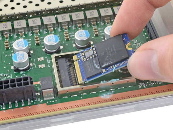
Once you’ve taken out the SSD screw, the SSD will gently lift up at a slight angle, giving you easy access!
– Grab the end of the SSD and gently wiggle it away from the M.2 board connector to set it free.
– When putting everything back together, slide the SSD in at a slight angle into its board connector, and then lay it flat again, securing it with the SSD screw.