Clear, local pricing for phone, tablet, Mac/PC, and console repairs — same-day service available in Laurel, MS.
Repair Pricing & Service Overview
Honest, upfront pricing and fast diagnostics. We serve Laurel, Ellisville, Bay Springs, and nearby communities. Book online or walk in for a free diagnostic.
Location: 1503 Lakeview Rd, Laurel, MS 39440
Call: 601-699-8246
Price Checker
Select device type, brand and issue to see estimated pricing.
In the interest of transparency and good policy, we endeavor to keep these prices as accurate as possible, but these prices do fluctuate slightly from time to time (especially newer models - prices can drop suddenly!). The Price checker is meant to provide a general guide for pricing a repair and should be used to get an "idea" of the price range. For the most up to date prices, Call Us at 601-699-8246.
Battery Repair & Replacement
Fast battery replacements to restore full charge and runtime. Most standard phones installed in ~30 minutes. Extended batteries and tablets vary by model.
-
Phone Battery
iPhone / Android$59 – $129 -
Tablet / iPad Battery
iPad, Galaxy Tab$99 – $149 -
Extended Battery Install
Larger capacity & special installs$59.95+
All battery services include diagnostic testing, battery health assessment, and a limited warranty. Exact price determined after free diagnostic.
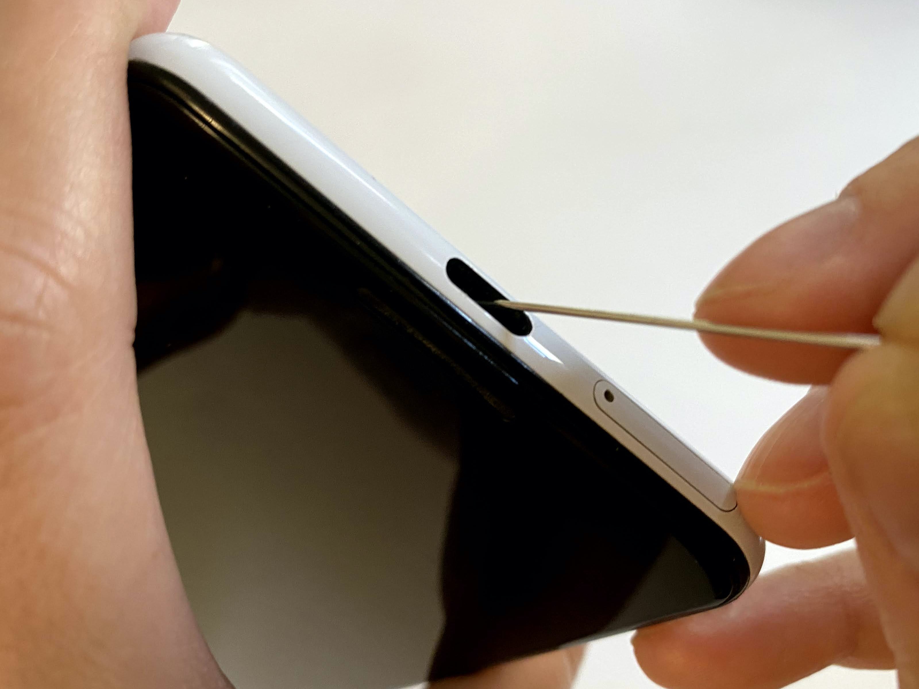
Charging Port & Connector Service
Port cleaning and replacement for phones and tablets. Quick maintenance often fixes intermittent charging or connection issues.
-
Port Cleaning & Blowout
Pro cleaning & inspection$19.95 -
Port Replacement
Connector replacement (model dependent)$59.95+
We test charging under load and inspect for corrosion; diagnostics free with paid repair.
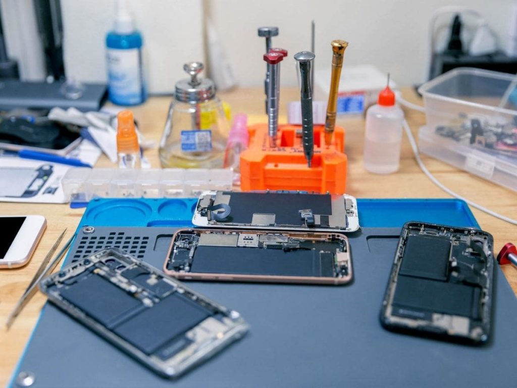
Phone & Tablet Pricing
Typical starting ranges. Final price shown after inspection — we always provide a written quote.
| Device | Example Models | Screen / LCD | Battery | Charging / Port |
|---|---|---|---|---|
| iPhone | 8, X, 11, 12, 13, 14, 15 | $79 – $249 | $59 – $129 | $19.95 – $129 |
| Samsung Galaxy | S8 – S21 / newer | $99 – $279 | $79 – $139 | $19.95 – $149 |
| Google Pixel | Pixel 3 – 7 | $79 – $199 | $79 – $129 | $19.95 – $129 |
| Tablet / iPad | iPad Air / Mini / Pro, Galaxy Tab | $149 – $499 | $99 – $229 | $59.95 – $249 |
Schedule a free diagnostic or get an on-site estimate via our booking page.
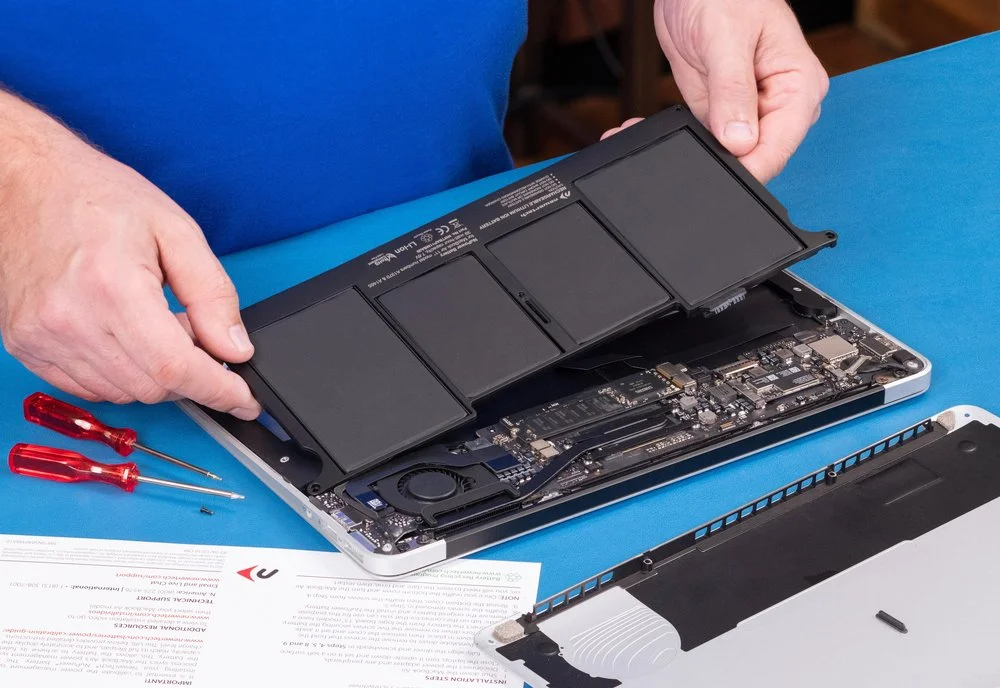
MacBook & PC Repair
Repairs and upgrades for Mac and Windows laptops and desktops. We handle screens, batteries, keyboard replacement, logic board diagnosis, data recovery, and SSD / RAM upgrades.
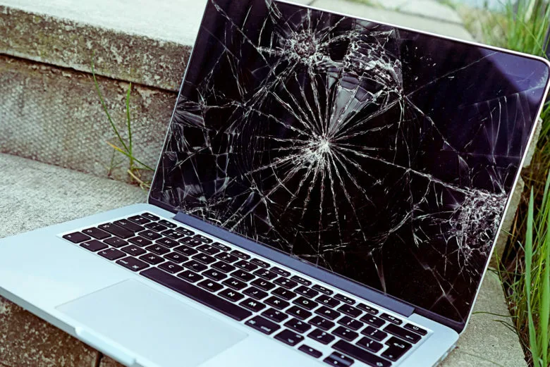
Screen Replacement
High-resolution and Retina displays — typical range $139 – $349.
Battery Replacement
Service starts at $99.95 (Mac & PC models vary).
Logic Board & Power
Board-level diagnostics & repair — typical range $149 – $399 depending on complexity.
Upgrades (SSD / RAM)
SSD installations from $89.95. RAM upgrades dependent on model.
Data safety & privacy guaranteed — we recommend a backup before logic-board work. Free diagnostics with any paid repair.
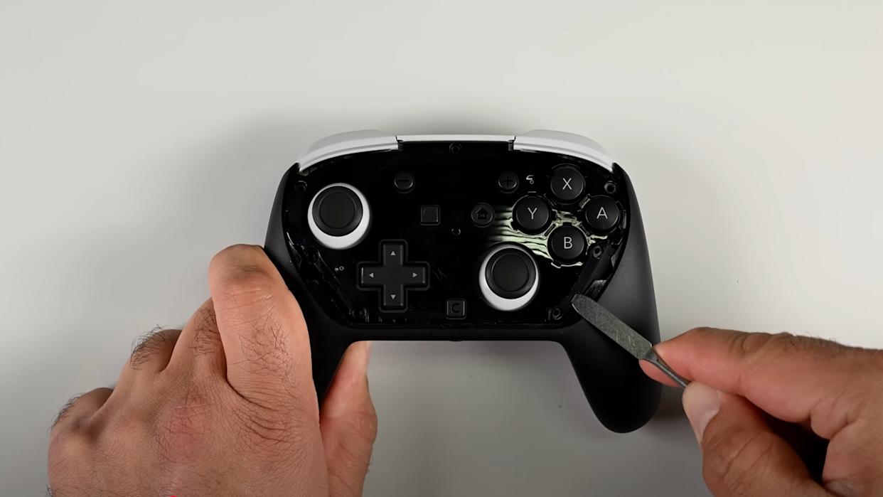
Gaming Console Repair
Nintendo Switch, PlayStation 5, and Xbox Series repairs — HDMI fixes and replacements, fan & thermal service, disc reader and power repairs.
HDMI Repair
No image, dropped port smashes & Xbox loose HDMI port fixes.
$99.95 – $149.95
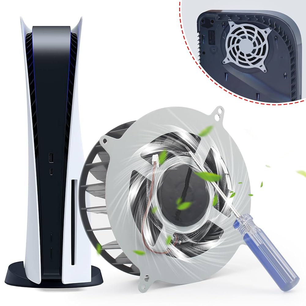
Fan & Thermal Service
Cleaning, paste replacement, liquid metal, and fan swaps.
$49 – $99
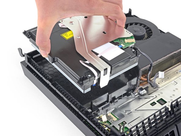
Disc / Cartridge Issues
Read errors, eject problems, slot cleaning.
$79 – $129
Diagnostics always performed before quotes. We repair internal board faults and offer realistic success estimates for corrosion or liquid damage.
Frequently Asked Questions & Pricing
Below are concise answers and typical price ranges for our most common repairs. Final pricing is confirmed after a free diagnostic and written quote.
- iPhone: $59 – $129
- Samsung Galaxy: $79 – $139
- Google Pixel: $79 – $129
- Tablet / iPad: $99 – $149
- Extended / high-capacity installs: from $59.95 additional (model dependent)
- MacBook / Laptop batteries: starting around $99.95 – $129 (varies by model)
- Port cleaning & blowout: $19.95
- Port replacement (phone/tablet): starting at $59.95+
- We test charging under load and inspect for corrosion; port replacements vary by model and whether board-level work is required.
- iPhone screens: $79 – $249
- Samsung Galaxy screens: $99 – $279
- Google Pixel screens: $79 – $199
- Tablet / iPad displays: $149 – $499 (Pro, laminated, or ProMotion displays cost more)
- MacBook / laptop screens: $139 – $349 (Retina / high-res displays on the upper end)
- MacBook screen replacement: $199 – $399 (model dependent)
- Laptop screen (PC): $139 – $349
- MacBook / laptop battery: starting around $99.95 – $129
- Logic board & power repairs: $149 – $399 (complex board-level work may be higher)
- SSD install: from $89.95 (plus SSD cost)
- Data recovery / transfer: from $79 (dependent on drive condition)
- Controller drift / controller repair: $39.95 – $89
- Fan / thermal service: $49 – $99
- Disc / cartridge reader repair: $79 – $129
- Power & board issues: $79 – $159 depending on fault complexity
Ready to get started?
Book online for the fastest service or call us now. Walk-ins welcome.
Schedule Repair Call / Text